ThermoFisher Scientific MaxQ 2000 CO2 Plus User manual

In the United States:
For customer service, call 1-800-766-7000
To fax an order, use 1-800-926-1166
To order online: thermofisher.com
Find out more at thermofisher.com
In Canada:
For customer service, call 1-800-234-7437
To fax an order, use 1-800-463-2996
To order online: thermofisher.ca
For Research Use Only. Not for use in diagnostic procedures. ©2020 Thermo Fisher Scientific Inc. All rights
reserved. All trademarks are the property of Thermo Fisher Scientific and its subsidiaries unless otherwise specified.
MaxQ 2000 CO2 Plus
Digital CO2 Resistant Shaker
Catalog #88881101B, #88881102B
#88881103B, #88881104B
Operation Manual 0000847
Visit us online to register your warranty
www.thermoscientific.com/labwarranty
User Manual

Thermo Scientific
1CO2 Resistant Shaker i
MANUAL NUMBER 0000-847
0
REV
0
ECR/ECN
10/ 11 /2020
DATE
Original
DESCRIPTION By
If you do, please contact us 8:00 a.m. to 6:00 p.m. (Eastern Time) at:
1-740-373-4763
1-800-438-4851
1-877-213-8051
http://www.thermoscientific.com
service.led.marietta@thermofisher.com
www.unitylabservices.com
Our Sales Support staff can provide information on pricing and give you quotations.
We can take your order and provide delivery information on major equipment items or
make arrangements to have your local sales representative contact you. Our products
are listed on the Internet and we can be contacted through our Internet home page.
Our Service Support staff can supply technical information about proper setup,
operation or troubleshooting of your equipment. We can fill your needs for spare or
replacement parts or provide you with on-site service. We can also provide you with a
quotation on our Extended Warranty for your Thermo Scientific products.
Whatever Thermo Scientific products you need or use, we will be happy to discuss
your applications. If you are experiencing technical problems, working together, we
will help you locate the problem and, chances are, correct it yourself...over the
telephone without a service call.
When more extensive service is necessary, we will assist you with direct factory
trained technicians or a qualified service organization for on-the-spot repair. If your
service need is covered by the warranty, we will arrange for the unit to be repaired at
our expense and to your satisfaction.
Regardless of your needs, our professional telephone technicians are available to assist you
Monday through Friday from 8:00 a.m. to 6:00 p.m. Eastern Time. Please contact us by
telephone or fax.
International customers, please contact your local Thermo Scientific distributor.
Direct
Toll Free, U.S. and Canada
FAX
Internet Worldwide Web Home Page
Tech Support Email Address
Certified Service Web Page
Do You Need Information or Assistance on
Thermo Scientific Products?
Thermo Scientific
1CO2 Resistant Shaker ii

Section 1
Universal (Aluminum) Platform Installation
18inch (Aluminum) Platform Installation
Rubber Mat Platform Installation
Connections of the Instrument
Section 2 Overview
Specifications
Environmental Conditions
Safety Tips
Storing the signal Cable
Output current of Control Box
Maximum Shaking Speed
Section 3 Operation
Operations on the Control Panel
Speed and Time Settings
Alarm System
Section 4 Application
Section 5 Safety Tips
Section 6 Optional Accessories
Section 7 Troubleshooting
Unpacking and Installation
Packing List
Contents
1
1
3
3
4
4
5
5
5
6
6
7
8
10
10
11
11
12
13
14
18
Thermo Scientific Thermo Scientific
1CO2 Resistant Shaker iii 1CO2 Resistant Shaker iiii

Section 1 Unpacking and Installation
1. Inspect contents upon receipt of
the instrument, if the instrument is
upside down, contact the
manufacturer immediately.
2. Check packing list below. If there
are any damaged or missing
items, contact the manufacturer.
3. Place the instrument on a level
and firm surface, to avoid vibration
and noise.
1 | Section 1 Unpacking and Installation MaxQ 2000 CO2 Plus 2
1.1 Packing List
Cat. No.
88881101B 88881102B 88881103B 88881104B
Picture
Model name
on carton
box label
MaxQ 2000
CO2 Plus,
100-240V,
for USA
MaxQ 2000
CO2 Plus,
100-240V,
various plugs
MaxQ 2000
CO2 Plus
Promotion
Package for
USA, includes
CO2 resistant
shaker
(88881101B),
Universal
Platform and
Flask Clamp
Starter Kit
MaxQ 2000
CO2 Plus
Promotion
Package for
EMEA & APAC,
includes CO2
resistant
shaker
(88881102B),
Universal
Platform &
Flask Clamp
Starter Kit
Main Body
Control Box
General
Power Adaptor
US Plug
CN Plug
EU Plug
UK Plug
N/A
N/A
N/A
N/A
N/A
N/A
N/A
N/A
1111
1111
1
1
1
1
1
1
1
1
1
1
1 1
Cat. No.
88881101B 88881102B 88881103B 88881104B
Picture
Model name
on carton
box label
MaxQ 2000
CO2 Plus,
100-240V,
for USA
MaxQ 2000
CO2 Plus,
100-240V,
various plugs
MaxQ 2000
CO2 Plus
Promotion
Package for
USA, includes
CO2 resistant
shaker
(88881101B),
Universal
Platform and
Flask Clamp
Starter Kit
MaxQ 2000
CO2 Plus
Promotion
Package for
EMEA & APAC,
includes CO2
resistant
shaker
(88881102B),
Universal
Platform &
Flask Clamp
Starter Kit
N/A
N/A
N/A
N/A
N/A
N/A
N/A
N/A
N/A
N/A
N/A
N/A
1
1
1
1
1
1
1
1
1
1
1
1
Universal
Platform(AL)
100ml
Flask Clamp
250ml
Flask Clamp
500ml
Flask Clamp
1L
Flask Clamp
2L
Flask Clamp
Data Port
1111

1. Place the instrument on a level and
firm surface, it must be capable of
supporting the weight and load of the
instrument, and the impact force
generated by the motion. Prepare
related parts (see Figure 1-1).
2. Install the horizontal universal
platform on the fixed plate of the Main
body, ensure all four mounting holes
in the universal platform and the four
threaded mounting holes are in
alignment.
3. Fasten the universal platform and the
fixed plate with four M4x14 cross
recessed countersink head screws.
1. Place the instrument on a level and
firm surface, it must be capable of
supporting the weight and load of the
instrument, and the impact force
generated by the motion. Prepare
related parts (see Figure 1-2).
2. Install the horizontal universal
platform on the fixed plate of the Main
body, ensure all four mounting holes
in the universal platform and the four
threaded mounting holes are in
alignment.
3. Fasten the universal platform and the
fixed plate with four M4x14 cross
recessed countersink head screws.
1) M4x14 cross recessed countersink
head screws
2) Universal (aluminum) platform
3) Main body of CO2 resistant shaker
1) M4x14 cross recessed countersink
head screws
2) 18inch (aluminum) platform
3) Main body of CO2 resistant shaker
3 Section 1 | Unpacking and Installation
1.2 Universal (Aluminum) Platform Installation 1.4 Rubber Mat Platform Installation
1.5 Connections of the Instrument
1.3 18inch (Aluminum) Platform Installation
Figure 1-1
Figure 1-3
Figure 1-2
①
①
②
②
③
③
1) Rubber mat
2) M4x10 cross recessed countersunk
head screws
3) Platform
4) Main body of CO2 resistant shaker
Note:
1) When disconnecting the control box from
the main body, please cut off the power
first. ▲
2) No special cable needed to connect with
4-20mA data port. ▲
1. Place the instrument on a level and
firm surface, it must be capable of
supporting the weight and load of the
instrument and the impact force
generated by the motion. Prepare
related parts (see Figure 1-3).
2. Install the horizontal platform on the
fixed plate of the Main body, ensure all
four mounting holes on the platform
and the four threaded mounting holes
are in alignment.
3. Fasten the platform and the fixed plate
with four M4x10 cross recessed
countersink head screws.
4. Place the rubber mat on the platform.
1) Main body of CO2 resistant shaker
2) Control box
3) Power adapter
4) Power cord
5) 4-20mA data port
Refer to Figure 1-4 when connecting the instrument.
①
②
③
④
Figure 1-4
⑤① ③ ④
②
MaxQ 2000 CO2 Plus 4
88881122B
88881122
88881123
88883101
2M 0.4M
88881181

Section 2 Overview
2.1 Specifications
Speed Range...........................................................30 to 600rpm
Speed Accuracy...................................................................±2rpm
Orbit Diameter....................................................................¢3mm
Motion Type.........................................................................Orbital
Speed Display...........................................................................LED
Maximum Load…………………………………............10kg @≤150rpm
Timing Range…………..……........................................0~99h 59min
Hour Display.……..........……............…...........……..........…….........LED
Minute Display...........…....................……....................…….........LED
Main body....................360×300×101mm(14.2×11.8×4.0inch)
Control Box...........................213×95×26mm(8.4×3.7×1.0inch)
Net Weight (Main body)..................................16.0kg(35.27lbs)
Net Weight (Control Box).....................................0.3kg(0.66lbs)
Gross weight.....................................................17.8kg(39.24lbs)
Requirement............................................AC100-240V, 50/60Hz
Certification.............................RoHS, WEEE, cCSAus, CE Mark,
FCC, CA 65, REACH, ICES-001
Noise level...........................................................................<60dB
Application Environmental Conditions: indoor use
Temperature....................................................................4 to 60℃
Altitude...........................................................................≤2,000 m
Humidity...................................................................... 20% to 99%
Co2 Concentration........................................................0% to 20%
Storage Environmental Conditions
Temperature....................................................................5 to 60℃
Altitude...........................................................................≤2,000 m
Humidity.......................................20% to 99%, non-condensing
2.2 Environmental Conditions
Rotation Speed
Load
Timer
Dimensions
Weight
Power Supply
Others
5 Section 2 | Overview
2.3 Safety Tips
1. Unplug and unload before moving the
unit.
2. This instrument uses a single-phase
AC100-240V 50/60Hz power supply.
3. Remove the power supply when the
instrument is in maintenance.
4. Do not clean the unit with flammable
or corrosive liquid.
5. Use specified power supply.
6. Maximum load 10kg(22.05 lbs) @≤
150 rpm.
7. To ensure proper operation, the unit
must be free of surrounding
obstructions.
2.4 Storing the signal Cable
To store the signal cable, simply open the
side plate on the main body.
Refer to Figure 2-1. The signal cable can
be placed inside.
1) Main body of CO2 resistant shaker
2) Side plate
3) Control box
Caution: When storing the cable, pay
attention to closing the side plate door, to
avoid pinching your fingers. ▲
③
①
②
Figure 2-1
MaxQ 2000 CO2 Plus 6
88883101

7 Section 2 | Overview
2.5 Orbital Speed vs. Output Current Monitoring System
Figure 2-2①
②
1) Control Box
2) Data Port
0.0
10.0
20.0
15.0
5.0
25.0
30 60054090 150 210 270 330 390 450
●
Table 2-1. Output current under different speed conditions
Output current(mA)Speed(rpm)
0
30
600
4
4.8
20
Flask size
Size Liquid volume Max Speed(rpm)
50ml ≤50ml 350
100ml ≤100ml 350
150ml ≤150ml 350
200ml ≤200ml 350
250ml ≤250ml 350
500ml ≤500ml 300
1000ml ≤1000ml 250
2000ml ≤2000ml 200
3000ml ≤3000ml 200
5000ml ≤5000ml 150
Flask size
Size Liquid volume Max Speed(rpm)
50ml ≤50ml 600
600
600
600
600
580
550
500
470
430
450
400
450
400
100ml ≤100ml
150ml ≤150ml
200ml ≤200ml
250ml ≤250ml
500ml ≤500ml
1000ml ≤1000ml
Max Flask
Capacity
30
15
15
15
15
9
≤500ml 4
4
4
4
3
3
1
1
2000ml ≤2000ml
≤1000ml
3000ml ≤3000ml
≤1500ml
5000ml ≤5000ml
≤2500ml
Output current(mA)
Speed(rpm)
2.6 Maximum Shaking Speed
Table 2-2. Maximum Shaking Speed on Rubber Platform in Relation to Flask Size
Table 2-3. Maximum Shaking Speed and Flask Capacity on Universal Platform
MaxQ 2000 CO2 Plus 8
88883101
88881181

9 Section 2 | Overview
Flask size
Size Liquid volume Max Speed(rpm)
50ml ≤50ml 550
100ml ≤100ml 550
150ml ≤150ml 550
550
200ml ≤200ml
250ml ≤250ml 500
500ml ≤500ml 400
1000ml ≤1000ml 280
Max Flask
Capacity
49
25
25
18
18
10
7
≤500ml 480
7
2000ml ≤2000ml 230
4
≤1000ml 430
4
3000ml ≤3000ml 200
4
≤1500ml 430
4
5000ml ≤5000ml 150
≤2500ml 280
2
2
Note:
1) The flask clamps (≤2L) can be placed anywhere on the universal (aluminum)
platform, even if the load is not balanced. ▲
2) Please refer to the "Liquid Volume" table in the specifications section for the
maximum load. ▲
Table 2-4. Maximum Shaking Speed and Flask Capacity on 18 inch (aluminum)
Platform
Note:
1) The flask clamps (<2L) can be placed anywhere on the 18inch (aluminum)
platform, even if the load is not balanced. ▲
2) Please refer to the "Liquid Volume" table in the specifications section for the
maximum load. ▲
Section 3 Operation
3.1 Operations on the Control Panel
The unit has been designed with a “soft
start/slow down” providing a
smooth acceleration/ deceleration
during operation. This feature will
decrease splashing of solutions from
vessels during operation.
Warning: The microprocessor control
system may take 1 minute to
synchronize the actual RPM of the
universal (aluminum) platform to the
desired RPM setting. Make sure that all
the flasks and test tubes are firmly
fixed on the universal platform and the
flask clamps are fasten securely
with the screws.
①
②
⑩
③
④
⑤
⑥
⑦
⑧
⑨
1) Display LED: Shows time or speed
2) RPM indicator light: LED shows
current speed
3) TIME indicator light: LED shows
current time
4) WARN indicator light: Over-speed
alarm
5) RUN indicator light: The instrument is
running
6) RPM/TIME Key: While instrument is in
operation, press to change time and
speed display; when setting
parameter, press to change minutes,
hour or speed.
7) Up Arrow Key: Increases value. Hold
for 3 seconds to increase rapidly
8) Down Arrow Key: Decreases value.
Hold for 3 seconds to decrease
rapidly.
9) Key: The power is On/Off.
10) Run/Stop Key: The instrument is
running or stopped.
MaxQ 2000 CO2 Plus 10

3.2 Speed and Time Settings
Speed setting
1. Press RPM/TIME key. The speed
indicator light is lit.
2. Press up and down arrow keys to
access the speed setting state, speed
value starts flashing.
3. Press up and down arrow keys to
change the speed value. Speed
increases or decreases. The minimum
unit is 1rpm.
4. During settings, the unit will reset to
current values if no value is input after
3 seconds.
5. Press “Run/Stop” key to run or stop.
Time setting
1. Press RPM/TIME key. The time
indicator light is lit.
2. Press up and down arrow keys to
access the time setting state. Speed
value starts flashing;
3. Press up and down arrow keys to
change the time value. Time increases
or decreases. The minimum unit is 1
minute or 1 hour.
4. During settings, the unit will reset to
current values if no value is input after
3 seconds.
5. Press “Run/Stop” key to run or stop.
Notes
1. When the shaker is running, the LED
display will switch between the speed
and timer function every 30 seconds
automatically. Press RPM/TIME key to
manually toggle between the speed
and timer value.
2. In “timer mode” the LED display will
show the remaining running time.
3. In “continuous mode” the LED display
will show elapsed run time.
4. After the run is complete, the LED
display will read “end”. Press any key
to place the shaker in standby mode.
3.3 Alarm System
Alarm System
1. During operation, the alarm will sound
after 10 seconds if the unit has not
begun shaking. In addition, the alarm
will sound and stop for the speed over
650 rpm after 2 seconds.
2. Once the shaker begins to alarm, the
RUN indicator light will not be visible
and the WARN indicator light will flash,
and the unit will stop running.
Power failure recovery
When the power supply is cut off
suddenly to the shaker, resulting in a
power failure, the unit will automatically
run at the previous set parameter upon
power restoration.
Section 4 Application
Application on Lab Benches
To operate the shaker outside of a CO2 incubator, refer to Specifications in Section 2.
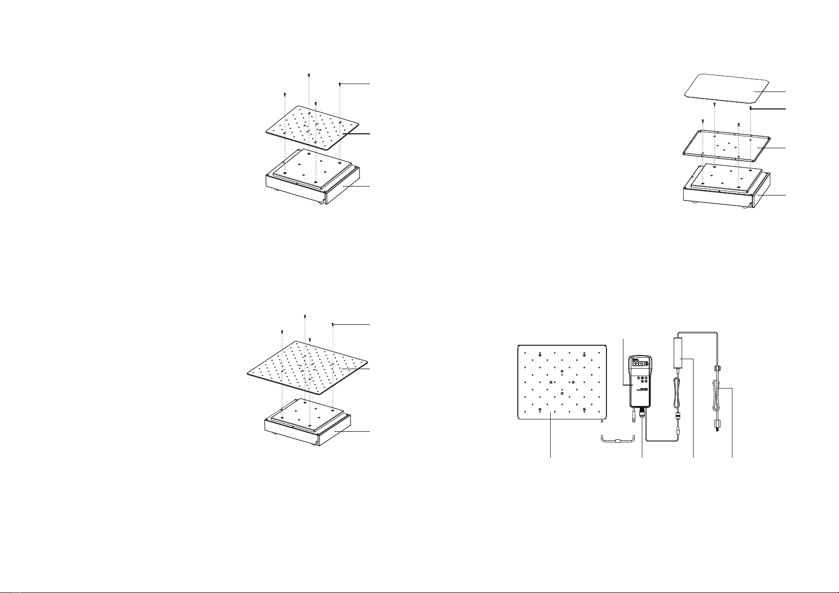
Application in CO2 Incubator
Place the main body of the shaker in the CO2 incubator, and use the
signal cable to connect the control box through the access port of the CO2
incubator. Refer to Figure 4-1.
Warning
1. Never put the control box in the CO2
incubator.
2. The back of control box is magnetized,
and can be attached on the surface of
the CO2 incubator.
3. When the main body of CO2 Resistant
Shaker is in operation in the CO2
incubator, keep a safe distance from
the inner wall of the CO2 incubator to
avoid collisions.
4. The main body of the shaker should
be connected to the control box wire
through the access port of the CO2
incubator.
5. If the cells are sensitive to vibrations,
do not put them in the same incubator
or on the shaker.
11 Section 3 | Operation
Figure 4-1
1) CO2 Incubator
2) Control Box
3) Power Cord
4) Main body of CO2 Resistant Shaker
①
②
③
④
MaxQ 2000 CO2 Plus 12
88883101

Safety Tips
1. Confirm local power supply voltage
before use the unit.
2. The unit must not be plugged into a
power supply extension with other
pieces of equipment.
3. The data cable between the main
body and control box cannot be
extended.
4. Never modify the supplied power
cables.
5. Service should only be performed by a
qualified professional.
6. In the following situations, the power
supply must be unplugged:
◆ When the unit is moved.
◆ When the control box is opened.
◆ When a fuse is replaced.
◆ When the equipment is not
functioning properly.
◆ When the equipment is not in use.
Maintenance
Surfaces can be cleaned with mild
detergent and water. Liquid should not
be allowed to enter inside the unit.
Clean spill
If accidental spillage of liquids or other
materials occur on the platform, shut
down the machine and clean up the
liquids or other materials immediately.
Note: If liquid has entered the unit,
remove the platform and clean it. ▲
1. Turn off the machine and unplug the
power cord.
2. Remove the platform (with 4 screws).
3. Remove top plate (with 7 screws).
4. Use 70% ETOH to clean the inner area.
5. All allow the unit to dry for one hour,
reassemble unit, and operate normally.
Section 6 Optional Accessories
Section 5 Safety Tips
Table 6-1. Universal (Aluminum) Platform
Description
50ml clamp
100ml clamp
150ml clamp
200ml clamp
250ml clamp
500ml clamp
1000ml clamp
2000ml clamp
3000ml clamp
5000ml clamp
Cat. No.
88881105
88881106
88881107
88881108
88881109
88881110
88881111
88881112
88881113
88881114
Dimensions
WxDxH mm( )
60×60×40
60×65×45
80×80×50
80×80×55
90×90×60
115×115×70
130×130×75
170×170×100
200×200×140
245×245×140
Max.
Qty.
30
15
15
15
15
9
4
4
2
1
Figure
500ml Infusion bottle clamp
1000ml Infusion bottle clamp
Fixed Tube rack 40ר14mm
Fixed Tube rack 40ר16mm
Funnel Clamp
88881115
88881116
88881118
88881119
88881117
100×100×95
265x120x140
265x120x140
N/A
6
4
2
2
2
MaxQ 2000 CO2 Plus 14
13 Section 5 | Safety Tips
2
285x125x17588881120
285x125x17588881121
Adjustable Tube rack
40ר16mm
1
360×300×588881122
Universal (Aluminum) platform
N/A
360x305x1088881123
Rubber Mat platform
Adjustable Tube rack
40ר14mm
2
125×125×125

MaxQ 2000 CO2 Plus 16
15 Section 6 | Optional Accessories
Description Cat. No. Dimensions
WxDxH mm( )
Max.
Qty.
Figure
Spring Wire Rack 88881125 350X240X80 1
Sticky Mat
88881126 140×140 4
Control Box
88883101 213×95×26 1
1
1
N/A
N/A
1
1
1
N/A
N/A
N/A
88881130
CN Plug
88881131
EU Plug
88881132
UK Plug
100ml flask clamp x 2
250ml flask clamps x 4
500ml flask clamps x 4
1L flask clamps x 2
2L flask clamp x 2
1
N/A
88881133
Flask Clamp Starter Kit
General Power Adaptor
US Plug
88881129
6130x90x1588881124
96-well microplate holder
49
25
25
18
18
10
7
4
4
2
12
9
4
4
6
4
285x125x17588881120
285x125x17588881121
Adjustable Tube rack
40ר16mm
1
88881122B
18inch (Aluminum) platform
N/A
360x305x1088881123
Rubber Mat platform
10130x90x1588881124
96-well microplate holder
Table 6-2. 18inch (Aluminum) Platform
Description
50ml clamp
100ml clamp
150ml clamp
200ml clamp
250ml clamp
500ml clamp
1000ml clamp
2000ml clamp
3000ml clamp
5000ml clamp
Cat. No.
88881105
88881106
88881107
88881108
88881109
88881110
88881111
88881112
88881113
88881114
Dimensions
WxDxH mm( )
60×60×40
60×65×45
80×80×50
80×80×55
90×90×60
115×115×70
130×130×75
170×170×100
200×200×140
245×245×140
Max.
Qty.
Figure
500ml Infusion bottle clamp
1000ml Infusion bottle clamp
Fixed Tube rack 40ר14mm
Fixed Tube rack 40ר16mm
Adjustable Tube rack
40ר14mm
Funnel Clamp
88881115
88881116
88881118
88881119
88881117
100×100×95
265x120x140
265x120x140
N/A
4
1
Data Port
41×14×14
125×125×125
457×457×6
88881180
88881181

Description Cat. No. Dimensions
WxDxH mm( )
Max.
Qty.
Figure
Spring Wire Rack 88881125 350X240X80 1
Sticky Mat
88881126 140×140 9
Control Box
88883101 213×95×26 1
1
1
N/A
N/A
1
1
1
N/A
N/A
N/A
88881130
CN Plug
88881131
EU Plug
88881132
UK Plug
100ml flask clamp x 2
250ml flask clamps x 4
500ml flask clamps x 4
1L flask clamps x 2
2L flask clamp x 2
1
N/A
88881133
Flask Clamp Starter Kit
General Power Adaptor
US Plug
88881129
MaxQ 2000 CO2 Plus 18
17 Section 6 | Optional Accessories
Section 7 Troubleshooting
To troubleshoot the unit, refer to the
table below. If your problem persists,
contact your local sales/service
representative.
Indicator off
No reaction
No rotating of platform
Loud noise
Other
Power disconnected
Power adapter failure
Switched off
Sensor failure
Main-board failure
The unit has been placed
on uneven surface
Platform loose
Accessories loose
Keep record for maintenance
Connect the power
Replace power adapter
Switch on
Contact local sales/service
Place the unit on level and
sturdy surface
Fasten platform
Fasten accessories
Solution
Cause
Error
1
Data Port
41×14×14
88881180
88881181

THERMO FISHER SCIENTIFIC STANDARD PRODUCT WARRANTY
The Warranty Period starts two weeks from the date your equipment is shipped from our facility. This allows for shipping time so the warranty will go
into effect at approximately the same time your equipment is delivered. The warranty protection extends to any subsequent owner during the first year
warranty period.
During the first two (2) years, component parts proven to be non-conforming in materials or workmanship will be repaired or replaced at Thermo's
expense, labor included. Installation and calibration are not covered by this warranty agreement. The Technical Services Department must be contact-
ed for warranty determination and direction prior to performance of any repairs. Expendable items, glass, filters and gaskets are excluded from this
warranty.
Replacement or repair of components parts or equipment under this warranty shall not extend the warranty to either the equipment or to the compo
nent part beyond the original warranty period. The Technical Services Department must give prior approval for return of any components or equipment.
At Thermo's option, all non-conforming parts must be returned to Thermo Fisher Scientific postage paid and replacement parts are shipped FOB desti-
nation.
THIS WARRANTY IS EXCLUSIVE AND IN LIEU OF ALL OTHER WARRANTIES, WHETHER WRITTEN, ORAL OR IMPLIED. NO WARRANTIES
OF MERCHANTABILITY OR FITNESS FOR A PARTICULAR PURPOSE SHALL APPLY. Thermo shall not be liable for any indirect or consequential
damages including, without limitation, damages relating to lost profits or loss of products.
Your local Thermo Sales Office is ready to help with comprehensive site preparation information before your equipment arrives. Printed instruction man-
uals carefully detail equipment installation, operation and preventive maintenance.
If equipment service is required, please call your Technical Services Department at 1-800-438-4851 (USA and Canada) or 1-740-373-4763. We're ready
to answer your questions on equipment warranty, operation, maintenance, service and special application. Outside the USA, contact your local dis-
tributor for warranty information.
Rev. 0 9/13
Table of contents