ThermoKey TKSmart TMC series User manual

Technical Manual – TC
Technisches Handbuch – TC
Manuel Technique – TC
Manuale tecnico – TC
Manual técnico – TC
PodrEcznik techniczny - TC
Series TMC
Commercial condensers TKSmart
Serie TMC
Gewerbe-Verflüssiger TKSmart
Serie TMC
Condenseurs Commerciaux TKSmart
Serie TMC
Condensatori commerciali TKSmart
Serie TMC
Condensadores comerciales TKSmart
Seria TMC
Skraplacze serii TKSmart
THE ORIGINAL VERSION OF THESE
INSTRUCTIONS IS IN ITALIAN
MT TC R MC GEN 04 2017
EN
IT
DE
ES
FR
PL

EN TECHNICAL MANUAL – TC
IT MANUALE TECNICO – TC
DE TECHNISCHES HANDBUCH – TC
ES MANUAL TÉCNICO – TC
FR MANUEL TECHNIQUE – TC
PL PODRECZNIK TECHNICZNY – TC
LANGUAGES SUMMARY
04
15
26
37
48
59
03
Heat Exchange Solutions
MT TC R MC GEN 04 2017
ThermoKey
2
Technical Manual TC
Series TMC
Commercial condensers TKSmart
THE ORIGINAL VERSION OF THESE
INSTRUCTIONS IS IN ITALIAN
MT TC R MC EN 04 2017
EN

Heat Exchange SolutionsThermoKey Technical Manual TC Instruction and technical data
5
EN
MT TC R MC EN 04 2017MT TC R MC EN 04 2017
PLEASE READ CAREFULLY AND FULLY UNDERSTAND ALL INFORMATION
CONTAINED IN THESE INSTRUCTIONS PRIOR TO THE DESIGN AND IN ANY
CASE BEFORE ANY HANDLING, UNPACKING, ASSEMBLING, POSITIONING
AND COMMISSIONING OF THE UNIT. THE MANUFACTURER ACCEPTS NO
RESPONSIBILITY FOR DAMAGES TO PERSONS OR PROPERTIES RESULTING
FROM FAILURE TO FOLLOW THE INSTRUCTIONS CONTAINED HEREIN.
The original version of this manual is in Italian, and it is available on the website:
www.thermokey.com.
The English translation is a true copy of the original document and it is available on the website:
www.thermokey.com.
Translations in other languages may contain errors; if in doubt, always refer back to the original
version in Italian or its translation into English.
ThermoKey S.p.A. Quality Management System is certified in conformity with ISO 9001,
ThermoKey S.p.A. Environmental Management System is certified in conformity with ISO 14001
and Safe Management System is certified in conformity with OHSAS 18001.
EN
Heat Exchange SolutionsThermoKey Technical Manual TC Instruction and technical data
08
EN
MT TC R MC EN 04 2017MT TC R MC EN 04 2017
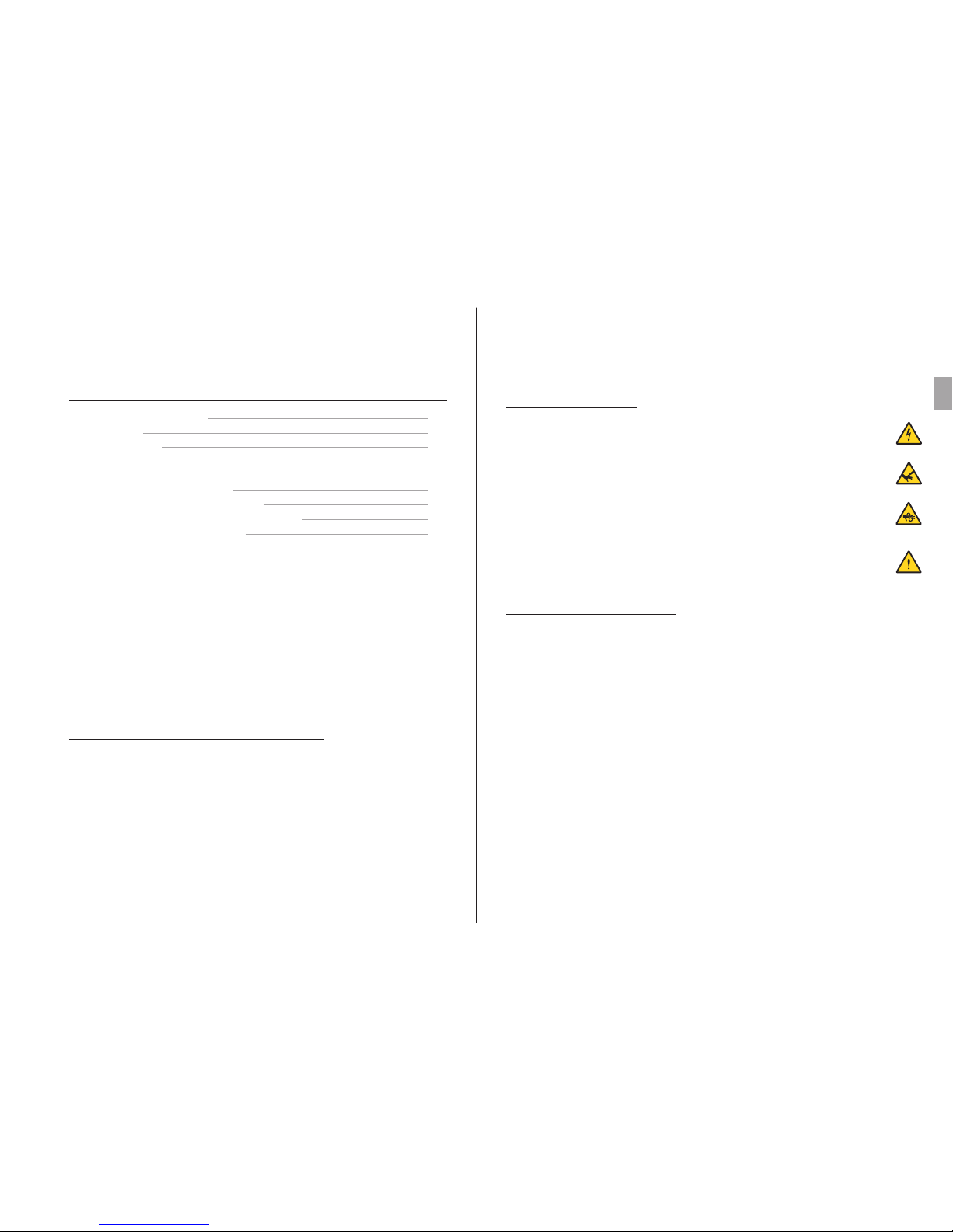
Danger of electrocution. e product is equipped with electric fans with an operating nominal voltage of 400V AC three-
phase or single phase 230V. e power supply lines must be tted with protection systems against electric shock and equipment
protection devices as required by law.
Risk of cutting. e heat exchanger, integral part of the product, is made of metal ns with unprotected sharp edges. e casing
is made of metal sheet components that in some points may present unprotected sharp edges.
Danger of moving parts. The product is equipped with electric fans fitted with a protection grid as provided by law. For
some products it could be possible to deliberately access moving parts (motor fan blades) from unprotected areas. Before
any access, please make sure that moving parts do not constitute a hazard to operators.
Danger of squashing limbs or persons. During handling, transportation and installation, operation and maintenance,
pay maximum attention to the indicated weight of each product to prevent tipping over or dangerous falls towards the
operators.
TC 2. Hazards
TC 3. Warnings
TC 3.1
Contents of the Technical Manual of the Product:
GENERAL INSTRUCTIONS FOR SAFE USE (I.G..)
INSTRUCTIONS FOR HANDLING AND UNPACKING (I.M.)
INSTRUCTIONS AND TECHNICAL DATA (T.C.)
SPECIFIC INSTRUCTIONS FOR USE AND MAINTENANCE (I.S.)
TC 3.2
This manual is section TC called INSTRUCTIONS AND TECHNICAL DATA of the Technical Manual of the Product.
For any information not covered in this manual, please refer to the other sections (I-II-IV) and, if in doubt, contact
the Manufacturer.
TC 3.3
is manual is an integral part of the TMC model and as such it must be kept throughout the operational life of the product.
TC 3.4
Any additional technical documentation regarding non-standard products is attached to this manual, becoming an
integral part of it and it is identified with a specific code indicated on the shipping documents.
TC 3.5
The product described in this manual is considered a partly completed machine, therefore not usable as supplied
but is a component for air conditioning and refrigeration systems and must be installed and commissioned only by
qualified operators (see chapter on installation and commissioning).
TC 1. Directives references
The product described in this manual is compliant with:
MACHINERY DIRECTIVE 2006/42/EC
LOW VOLTAGE DIRECTIVE 2006/95/EC
ELECTROMAGNETIC COMPATIBILITY DIRECTIVE2004/108/EC
PED DIRECTIVE 97/23/EC (2014/68/UE STARTING FROM 19/07/2016)
ERP DIRECTIVE 2009/125/EC
TC 1. DIRECTIVES REFERENCES
TC 2. HAZARDS
TC 3. WARNINGS
TC 4. INTENDED USE
TC 5. INSPECTION, HANDLING AND TRANSPORT
TC 6. INSTALLATION AND COMMISSIONING
TC 7. GENERAL MAINTENANCE AND CONTROL
TC 8. WIRING DIAGRAMS OF FANS
TC 9. DIMENSIONS - TECHNICAL DATA
SUMMARY
07
08
08
09
09
11
11
12
13
07
Heat Exchange SolutionsThermoKey Technical Manual TC Instruction and technical data
10
EN
MT TC R MC EN 04 2017MT TC R MC EN 04 2017
TC 5.4
Unpack the product as close as possible to its installation site (see also installation and commissioning). In general the
product must not be transported or handled without its original packaging.
TC 5.5
During handling of the unpacked unit for installation, use protection to prevent injuries caused by sharp edges such as ns or
casing parts (see DPI Technical Manual Section I chapter IG 6).
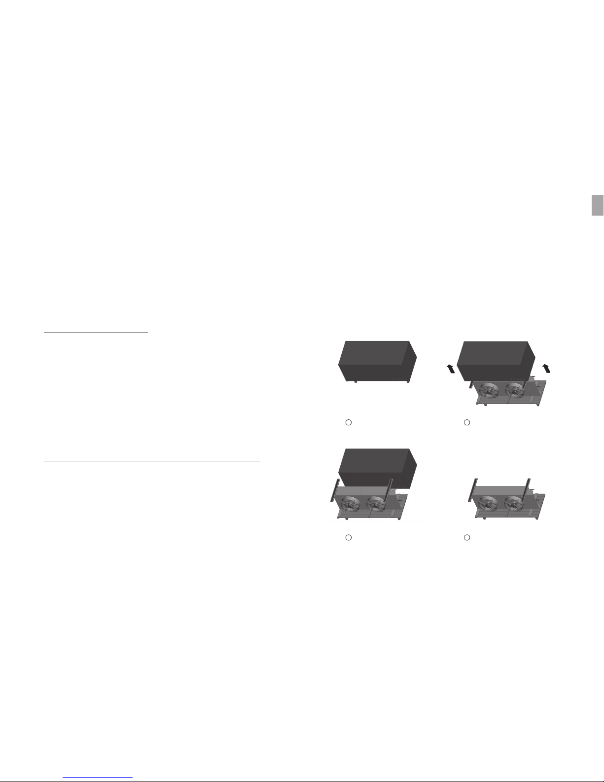
Please nd below the unpacking procedure:
TKSmart as shipped
Remove the 4 screws
Remove the carton box
Please read the documentation attached for
more information
1
3
2
4
09
TC 3.6
Each product is supplied with EC Declaration of Incorporation
TC 3.7
Additional product documentation, consisting of catalogues, guides and technical bulletins, is provided directly
by ThermoKey and is available on the website www.thermokey.com.
CATALOGUES – http://www.thermokey.com/Cataloghi.aspx
MANUALS – http://www.thermokey.com/Manuali.aspx
TC 4. Intended use
TC 4.1
The model must be used exclusively for the purpose indicated below, otherwise its use is considered improper and
exempts the manufacturer from any responsibility.
TC 4.2
TKSmart series microchannel condensers are used as condensers in HVAC&R applications. The product is not
provided with a dedicated subcooling circuit. The thermodynamic performances are defined in accordance with
EN 327.
TC 4.3
The standard model is equipped with electrical fans not suitable to withstand additional static pressures.
TC 4.4
If in doubt regarding the intended use of the product, please contact the Manufacturer.
TC 5. Inspection, handling and transport
TC 5.1
Upon receipt of the product, check the integrity of the packaging and of the product; immediately notify any damage
to the carrier. The packaging is manufactured in accordance with the model, the appropriate means of transport and
the correct handling.
TC 5.2
During transport and handling of the packed product, avoid any excessive and improper stress on the package.
TC 5.3
During transport and handling of the packed product, use appropriate protection to avoid any injury caused by
packaging parts such as nails, boards or cardboards and parts of the product such as fins or casing parts
(see DPI Technical Manual Section I chapter IG 6).

Heat Exchange SolutionsThermoKey Technical Manual TC Instruction and technical data
1211
EN
MT TC R MC EN 04 2017MT TC R MC EN 04 2017
TC 7.2
The product mainly consists of a finned heat exchanger with microchannel technology, structural frame in aluminium
metal sheets and electric fans.
TC 7.3
Periodically check the fixing points of the model, electrical connections and connections to the refrigerant line.
TC 7.4
Provide for periodic cleaning of the casing and the heat exchanger using suitable detergents or possibly water and soap
with a neutral pH. Do not use harsh detergents, solvents, acidic or basic solutions containing mainly copper, chlorine
or ammonia. Avoid the use of abrasives in general. If the use of sanitising products is required, check their compatibility
with the materials. If in doubt, contact the Manufacturer, requiring the specification “how to use microchannel cores”.
TC 7.5
Inspection and maintenance intervals depend on the type of plant, therefore are to be defined by experienced and
qualified personnel.
TC 7.6
For any operation on the product not described in this manual, please contact the Manufacturer.
TC 7.7
Avoid carrying out on/off settings both on the air and the refrigerant side, if the air temperature is lower than -10 °C
in order to avoid thermal shocks.
TC 7.8
The electric fans are equipped with a load-bearing protective grille to allow any replacement operations to be done
completely from the outside.
TC 8. Wiring diagrams of fans
TC 8.1
The frame of each model is equipped with a ground terminal (PE) with an identification tag. It is mandatory to
connect the ground terminal of the unit to the plant or to the external conductor of the earthing system.
TC 8.2
In models with wired electrical fans it is mandatory to connect the protection conductors of the electrical fans to the
plant or to the external conductor of the earthing system.
TC 8.3
It is mandatory to use protection systems against electric shock and protection of the equipment on the power lines
of the electrical fans. The fan assemblies are equipped with thermal contacts, normally closed, inserted in the motor
windings. Connect the thermal contacts to protect the motor from overheating.
Warning: over-temperature may not directly arise from an over-current. Please be aware that the temperature switch
closes again itself when the temperature decreases without a manual reset.
TC 6.1
The installation and commissioning of the product must be performed by qualified and experienced personnel.
TC 6.2
Check that the support structures and anchoring devices comply with the weight and shape of the product (see chapter
Dimensions and Technical Data).
TC 6.3
Fix the unit to all points provided (see chapter Dimensions) with adequate anchors and in accordance with the total weight
(net weight of the product, weight of the refrigerant, weight of the heat exchanger, weight of any ice accumulation).
TC 6.4
The product is not designed to support additional loads.
TC 6.5
Check that the electrical supply complies with the specifications as indicated on the technical data label.
TC 6.6
Before connecting the product, verify the presence of shut-off and sectioning devices on the power supply line,
protection against electric shock, protection of equipment and anything else required by law.
TC 6.7
If speed controllers are used for the electric fan, verify their compatibility. Non-compliant devices may generate noise
and may damage the motors; the Manufacturer does not guarantee the rated performance for models equipped with
speed controllers.
TC 6.8
Check that the operating condition limits (humidity, temperatures and pressure) meet the specific requirements of
the product selection.
TC 6.9
Access to the installed unit, for any type of intervention, must be reserved to experienced personnel qualied to run the
system, according to current regulations.
TC 6. Installation and commissioning
TC 7. General maintenance and control
TC 7.1
Before performing any maintenance work, make sure that the power supply line of the product has been sectioned:
the electrical parts may be connected to automatic controls. All maintenance work should be performed by
qualified and experienced personnel.
Heat Exchange SolutionsThermoKey Technical Manual TC Instruction and technical data
1413
EN
MT TC R MC EN 04 2017MT TC R MC EN 04 2017
TMCH1150HLLD
TMCH1150HLLY
TMCH1150HLLM
Model
TMCH1250HLLD
TMCH1250HLLY
TMCH1250HLLM
TMCH1350HLLD
TMCH1350HLLY
TMCH1350HLLM
Weigh t 38,5 kg
Volume 1,6 dm³
Connection
IN 1 x 22 mm
OUT 1 x 22 mm
Weigh t 72 kg
Volume 2,4 dm³
IN 1 x 22 mm
OUT 1 x 22 mm
Weigh t 105,5 kg
Volume 3,2 dm³
IN 1 x 28 mm
OUT 1 x 28 mm
W
L
H
Size horizontal air flow
W
H
L
780 mm
644 mm
1067 mm
W
H
L
780 mm
644 mm
1817 mm
W
H
L
780 mm
644 mm
2567 mm
W
L
H
W
H
L
674 mm
911 mm
1067 mm
W
H
L
674 mm
911 mm
1817 mm
W
H
L
674 mm
911 mm
2567 mm
Size vertical air flow
Scale 1:20
TMCH1150HUUD
TMCH1150HUUY
TMCH1150HUUM
Model
TMCH1250HUUD
TMCH1250HUUY
TMCH1250HUUM
Weigh t 56 kg
Volume 2,8 dm³
Weigh t 96 kg
Volume 4,4 dm³
W
H
L
973 mm
1006 mm
1347 mm
W
L
H
W
L
H
IN 1 x 28 mm
OUT 1 x 28 mm
Scale 1:20
W
H
L
Size horizontal air flow
875 mm
943 mm
1347 mm
W
H
L
875 mm
943 mm
2347 mm
Connection
IN 1 x 22 mm
OUT 1 x 22 mm
Size vertical air flow
W
H
L
973 mm
1006 mm
2347 mm
Scale 1:20
W
L
H
W
L
H
TMCH1163HUUD
TMCH1163HUUY
Model
TMCH1263HUUD
TMCH1263HUUY
Weigh t 63 kg
Volume 2,8 dm³
Weigh t 110 kg
Volume 4,4 dm³
Connection
IN 1 x 28 mm
OUT 1 x 28 mm
IN 1 x 28 mm
OUT 1 x 28 mm
W
H
L
W
H
L
875 mm
943 mm
1347 mm
W
H
L
W
H
L
875 mm
943 mm
2347 mm
973 mm
993 mm
1347 mm
973 mm
993 mm
2347 mm
Size horizontal air flow Size vertical air flow
1X500 LL – 2X500 LL – 3X500 LL
1X500 UU – 2X500 UU
1X630 UU – 2X630 UU
TC 8.4
Strictly follow the wiring diagrams in order to avoid damage to the motors (a, b, c.....)
TC 8.5
For models fitted with non-standard electrical fans, please refer to the wiring diagrams and consumption indicated in
the supplementary sheets and on the rating plate.
TC 8.6
Before using speed regulation systems for the electrical fans, check their compatibility, non-compatible controllers may
generate noise and may damage the fans; the Manufacturer does not take any responsibility regarding the performance
of the products equipped with control systems unless they are dened in the oer.
Electrical values of standard fans:
For other versions of fans, please contact ThermoKey.
Rpm: 1430 rpm
Power: 160 W
Current: 0,73 A
Rpm: 1340/1060 rpm
Power: 710/480 W
Current: 1,4/0,8 A
Rpm: 1300 rpm
Power: 680 W
Current: 3,0 A
Rpm: 1340/1070 rpm
Power: 1900/1350 W
Current: 3,2/2,2 A
Diameter: 400 (M)
Nominal voltage: 230 V
Frequency: 50 H
Diameter: 500 (D/Y)
Nominal voltage: 400 V
Frequency: 50 H
Diameter: 500 (M)
Nominal voltage: 230 V
Frequency: 50 H
Diameter: 630 (D/Y)
Nominal voltage: 400 V
Frequency: 50 H
W
L
H
W
L
H
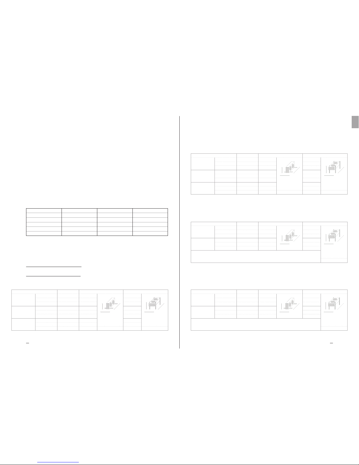
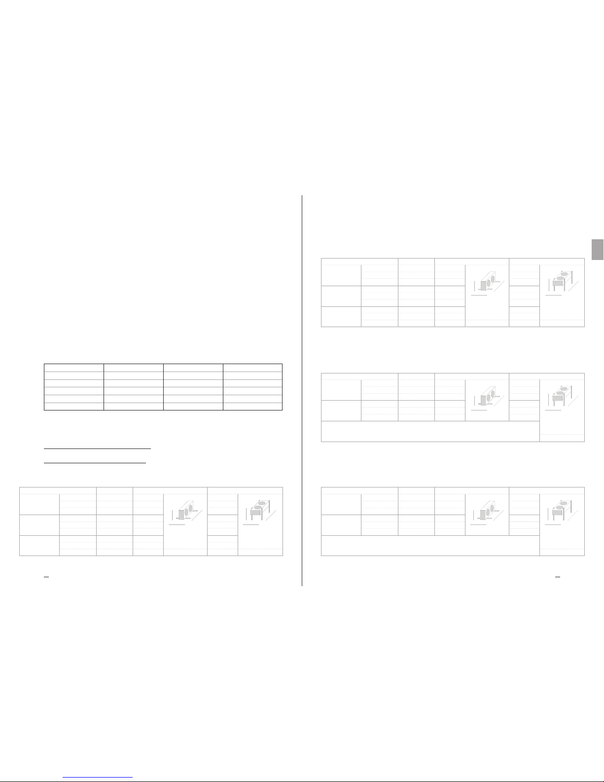
TMCH1140HLLM
TMCH1240HLLM
TMCH1340HLLM
Weigh t 35 kg
Volume 1,6 dm³
Weigh t 65 kg
Volume 2,4 dm³
Weigh t 95 kg
Volume 3,2 dm³
Connection
IN 1 x 22 mm
OUT 1 x 22 mm
IN 1 x 22 mm
OUT 1 x 22 mm
IN 1 x 28 mm
OUT 1 x 28 mm
Model
W
H
L
Size horizontal air flow
780 mm
644 mm
1067 mm
W
H
L
780 mm
644 mm
1817 mm
W
H
L
780 mm
644 mm
2567 mm
W
H
L
Size vertical air flow
674 mm
879 mm
1067 mm
W
H
L
674 mm
879 mm
1817 mm
W
H
L
674 mm
879 mm
2567 mm Scale 1:20
TC 9. Dimensions
— Technical Data
1X400 LL – 2X400 LL – 3X400 LL
Manuale tecnico TC
Serie TMC
Condensatori commerciali TKSmart
LA VERSIONE ORIGINALE DELLE PRESENTI ISTRUZIONI
È IN LINGUA ITALIANA
MT TC R MC IT 04 2017
IT

Manuale Tecnico TC Istruzioni e dati tecnici
1716
Heat Exchange SolutionsThermoKey
IT
MT TC R MC IT 04 2017 MT TC R MC IT 04 2017
LEGGERE ATTENTAMENTE E COMPRENDERE COMPLETAMENTE TUTTE
LE INFORMAZIONI CONTENUTE IN QUESTE ISTRUZIONI PRIMA DELLA
PROGETTAZIONE ED IN OGNI CASO PRIMA DI EFFETTUARE QUALUNQUE
OPERAZIONE DI MOVIMENTAZIONE, DISIMBALLAGGIO, MONTAGGIO,
POSIZIONAMENTO E MESSA IN ESERCIZIO DELL’APPARECCHIO.
THERMOKEY DECLINA OGNI RESPONSABILITÀ PER DANNI A PERSONE
O COSE DERIVANTI DALLA MANCATA OSSERVANZA DELLE INDICAZIONI
CONTENUTE NEL PRESENTE DOCUMENTO.
L’originale del presente manuale è in italiano , ed è reperibile sul sito internet: www.thermokey.com.
La traduzione in inglese è conforme all’originale ed è reperibile sul sito internet: www.thermokey.com.
Le traduzioni in altre lingue possono contenere errori; in caso di dubbio fare sempre riferimento
alla versione originale in italiano od alla sua traduzione in inglese.
Il sistema di gestione Qualità della ThermoKey è certificato in conformità alla norma ISO 9001,
il Sistema di Gestione Ambiente è certificato in conformità alla norma ISO 14001 e il Sistema di
Gestione Sicurezza è certificato in conformità alla norma OHSAS 18001.

Manuale Tecnico TC Istruzioni e dati tecnici
1918
Heat Exchange SolutionsThermoKey
IT
MT TC R MC IT 04 2017 MT TC R MC IT 04 2017
TC 1. Riferimenti Normativi
Il prodotto descritto in questo manuale risulta conforme alla:
DIRETTIVA MACCHINE 2006/42/EC
DIRETTIVA BASSA TENSIONE 2006/95/EC
DIRETTIVA COMPATIBILITA' ELETTROMAGNETICA 2004/108/EC
DIRETTIVA PED 97/23/EC (DAL 19/07/2016 2014/68/UE)
DIRETTIVA ErP 2009/125/EC
Pericolo di elettrocuzione. Il prodotto è allestito con elettroventilatori con tensione nominale di funzionamento di 400V
AC trifase o 230V monofase. Le linee di alimentazione elettrica dovranno utilizzare i sistemi di protezione contro la scossa
elettrica e di protezione dell’equipaggiamento previsti dalla normativa vigente.
Pericolo di taglio. Lo scambiatore di calore, parte integrante del prodotto, è costituito da alette metalliche con bordi taglienti, non
protette. La carrozzeria è costituita da componenti in lamiera che in alcuni punti possono presentare bordi taglienti non protetti.
Pericolo parti in movimento. Il prodotto è allestito con elettroventilatori dotati di griglia di protezione secondo
quanto previsto dalla normativa vigente. Per alcuni prodotti potrebbe essere possibile accedere volutamente alle parti
in movimento (pale dei motoventilatori) da zone non protette. Prima di qualsiasi accesso assicurarsi che le parti
in movimento non possano costituire pericolo agli operatori.
Pericolo di schiacciamento degli arti o della persona. Durante le fasi di movimentazione, trasporto ed installazione,
funzionamento e manutenzione, porre la massima attenzione al peso indicato di ogni prodotto per evitare ribaltamenti
o cadute pericolose verso gli operatori.
TC 2. Pericoli
TC 3. Avvertenze
TC 3.1
Contenuto del Manuale Tecnico di prodotto:
ISTRUZIONI GENERALI PER UN USO SICURO (IG)
ISTRUZIONI PER LA MOVIMENTAZIONE ED IL DISIMBALLO (IM)
ISTRUZIONI E DATI TECNICI (TC)
ISTRUZIONI SPECIFICHE D’USO E MANUTENZIONE (IS)
TC 3.2
Questo manuale è la sezione TC denominata ISTRUZIONI E DATI TECNICI del Manuale Tecnico di prodotto.
Per qualsiasi informazione non contemplata nel presente manuale fare riferimento alle altre sezioni (IG, IM, IS) e in
caso di dubbio contattare ThermoKey.
TC 3.3
Questo manuale è parte integrante dei modelli TMC e come tale deve essere conservarto per tutto il periodo di vita del prodotto.
TC 3.4
Eventuale documentazione tecnica supplementare relativa ai prodotti non standard è allegata al presente manuale,
è integrante ed è codificata con codice specifico indicato sui documenti di spedizione.
TC 3.5
Il prodotto descritto in questo manuale è considerato una quasi-macchina quindi non utilizzabile così come fornito
ma è un componente per impianti di condizionamento o refrigerazione e deve essere installato e messo in servizio solo
da operatori qualificati (vedere capitolo relativo ad installazione e messa in opera).
TC 1. RIFERIMENTI NORMATIVI
TC 2. PERICOLI
TC 3. AVVERTENZE
TC 4. DESTINAZIONE D’USO
TC 5. ISPEZIONE, MOVIMENTAZIONE E TRASPORTO
TC 6. INSTALLAZIONE E MESSA IN OPERA
TC 7. MANUTENZIONE GENERALE E CONTROLLO
TC 8. SCHEMI DI COLLEGAMENTO DEI MOTOVENTILATORI
TC 9. CARATTERISTICHE DIMENSIALI – DATI TECNICI
INDICE
18
19
19
20
20
22
22
23
24

Manuale Tecnico TC Istruzioni e dati tecnici
2120
Heat Exchange SolutionsThermoKey
IT
MT TC R MC IT 04 2017 MT TC R MC IT 04 2017
TC 3.6
Ogni prodotto è corredato di Dichiarazione di Incorporazione CE.
TC 3.7
Ulteriore documentazione relativa al prodotto, costituita da cataloghi, guide e bollettini tecnici, è fornita
direttamente dal Costruttore reperibile sul sito internet www.thermokey.com.
CATALOGHI – http://www.thermokey.com/Cataloghi.aspx
MANUALI – http://www.thermokey.com/Manuali.aspx
TC 4. Destinazione d'uso
TC 4.1
Il modello deve essere utilizzato esclusivamente per lo scopo di seguito indicato altrimenti, l’uso è da considerarsi
improprio ed esonera ThermoKey da qualsiasi responsabilità conseguente.
TC 4.2
I condensatori a microcanali della serie TKSmart sono utilizzati come condensatori in applicazioni HVAC&R.
Non è provvisto di un circuito dedicato di sottoraffreddamento. Le prestazione termodinamiche sono definite
secondo la EN 327.
TC 4.3
Il modello standard è equipaggiato con motoventilatori non adatti a sopportare prevalenze statiche aggiuntive.
TC 4.4
In caso di dubbio sulla destinazione d'uso contattare ThermoKey.
TC 5. Ispezione, movimentazione e trasporto
TC 5.1
Al ricevimento del modello controllare lo stato di integrità dell'imballaggio e del prodotto; contestare subito al
trasportatore qualsiasi danno eventuale verificatosi. L’imballaggio è fabbricato conformemente al modello, agli
adeguati mezzi di trasporto e di movimentazione.
TC 5.2
Durante il trasporto e la movimentazione del modello nel suo imballaggio, evitare sollecitazioni non conformi e
improprie sul prodotto imballato.
TC 5.3
Durante il trasporto e la movimentazione del prodotto imballato, utilizzare apposite protezioni per evitare di ferirsi
con le parti dell’imballaggio come chiodi, tavole o cartone e le parti del modello come le alette o la carrozzeria (vedi
DPI manuale tecnico sezione I cap IG 6).
TC 5.4
Disimballare il modello il più vicino possibile al luogo di installazione (vedi anche installazione e messa in opera).
In generale il modello non deve essere trasportato o movimentato privo dell’imballaggio originale.
TC 5.5
Durante la movimentazione per l'installazione del modello disimballato, utilizzare apposite protezioni per evitare di ferirsi
con le parti taglienti come le alette o la carrozzeria (vedi DPI manuale tecnico sezione I cap IG6).
Si riportano di seguito le operazioni di disimballo:
TKSmart imballato
Rimuovere le 4 viti
Rimuovere l’imballo in cartone
Per cortesia leggere la documentazione
allegata per maggiori informazioni
1
3
2
4

Manuale Tecnico TC Istruzioni e dati tecnici
2322
Heat Exchange SolutionsThermoKey
IT
MT TC R MC IT 04 2017 MT TC R MC IT 04 2017
TC 6.1
L’installazione e la messa in opera del modello deve essere eseguita da personale esperto e qualificato.
TC 6.2
Verificare che le strutture di supporto e gli ancoraggi siano conformi al peso ed alla forma del modello (vedi capitoli
Caratteristiche Dimensionali e Dati Tecnici).
TC 6.3
Fissare il modello a tutti i punti previsti (vedi capitolo Caratteristiche Dimensionali) con ancoraggi adeguati e conformi al
peso complessivo (peso netto del modello, peso del refrigerante, peso dell’eventuale accumulo di neve sullo scambiatore).
TC 6.4
Il modello non è progettato per supportare carichi aggiuntivi.
TC 6.5
Verificare che la linea di alimentazione elettrica sia conforme alle caratteristiche del modello indicate sui dati di targa.
TC 6.6
Prima di collegare il modello verificare che siano stati utilizzati i dispositivi di sezionamento ed interruzione dalla rete
di alimentazione, di protezione contro la scossa elettrica, di protezione dell’equipaggiamento e quant’altro previsto
dalla normativa vigente.
TC 6.7
Se venissero utilizzati dispositivi di regolazione del numero di giri dei motoventilatori verificarne la compatibilità,
dispositivi non compatibili possono generare rumorosità e danneggiamenti ai motoventilatori; ThermoKey non
garantisce le prestazioni indicate per modelli equipaggiati con dispositivi di regolazione.
TC 6.8
Verificare che i limiti di funzionamento (umidità, temperature e pressioni) siano conformi alle caratteristiche di
selezione del prodotto.
TC 6.9
L’accessibilità al modello installato, per qualsiasi tipo di intervento, deve essere riservata a personale esperto e
qualificato alla conduzione dell’impianto, secondo le norme vigenti.
TC 6. Installazione e messa in opera
TC 7. Manutenzione generale e controllo
TC 7.1
Prima di effettuare qualsiasi intervento di manutenzione accertarsi che l’alimentazione elettrica del modello
sia stata sezionata: le parti elettriche potrebbero essere collegate a controlli automatici. Tutte le operazioni di
manutenzione devono essere effettuate da personale esperto e qualificato.
TC 7.2
Il modello è costituito principalmente da: uno scambiatore di calore a pacco alettato con tecnologia a microcanale,
una carrozzeria portante in lamiera di alluminio e da elettroventilatori.
TC 7.3
Verificare periodicamente i fissaggi del modello, le connessioni elettriche e i collegamenti alla linea del refrigerante.
TC 7.4
Provvedere alla pulizia periodica della carrozzeria e dello scambiatore utilizzando detergenti idonei o eventualmente
dell’acqua e sapone con pH neutro. Non utilizzare detergenti aggressivi, solventi, soluzioni acide o basiche e contenenti
principalmente rame, cloro o ammoniaca. Evitare l’utilizzo di abrasivi in genere. Se si dovessero utilizzare igienizzanti
verificarne la compatibilità con i materiali. In caso di dubbio contattare ThermoKey, richiedendo la specifica “how to
use microchannel cores”.
TC 7.5
I periodi di verifica e manutenzione sono dipendenti dalla tipologia di impianto, pertanto da definirsi da personale
esperto e qualificato.
TC 7.6
Per qualsiasi operazione sul modello, non descritta su questo manuale, contattare ThermoKey.
TC 7.7
Evitare di fare regolazioni on/off sia lato refrigerante che aria, qualora la temperatura dell’aria sia inferiore a -10°C.
TC 7.8
I motoventilatori sono dotati di griglia di protezione portante per permettere le eventuali operazioni di sostituzione
completamente dall’esterno.
TC 8. Schemi di collegamento
dei motoventilatori
TC 8.1
Il telaio di ogni modello è dotato di un polo di terra (PE) con etichetta di identificazione. E’ obbligatorio collegare il
polo di terra del modello all’impianto o al conduttore esterno di messa a terra.
TC 8.2
Nei modelli con motoventilatori cablati è obbligatorio collegare i conduttori di protezione dei motoventilatori
all’impianto o al conduttore esterno di messa a terra.
TC 8.3
È obbligatorio utilizzare i sistemi di protezione contro la scossa elettrica e di protezione dell’equipaggiamento sulle
linee di alimentazione dei motoventilatori. I motoventilatori sono dotati di termocontatti normalmente chiusi inseriti
negli avvolgimenti del motore. Collegare i termocontatti per proteggere il motore dalle sovratemperature.

Manuale Tecnico TC Istruzioni e dati tecnici
2524
Heat Exchange SolutionsThermoKey
IT
MT TC R MC IT 04 2017 MT TC R MC IT 04 2017
Attenzione che una sovratemperatura può non essere direttamente dipendente da una sovracorrente. Attenzione che
il termocontatto richiude al riabassarsi della temperatura senza un ripristino manuale.
TC 8.4
Seguire rigorosamente gli schemi elettrici riportati per evitare il danneggiamento dei motori (a,b,c.....).
TC 8.5
Per modelli che montano motoventilatori non standard fare riferimento agli schemi ed assorbimenti indicati nei fogli
supplementari e nei dati di targa.
TC 8.6
Prima di utilizzare sistemi di regolazione del numero di giri dei motoventilatori vericarne la compatibilità, regolatori non
compatibili possono generare rumorosità e danneggiamenti ai motoventilatori; ermoKey non si assume responsabilità
alcuna sulle prestazioni dei modelli equipaggiati con sistemi di regolazione se non deniti in fase di oerta.
Si riportano i valori elettrici dei ventilatori standard:
Per altre versioni di ventilatori, contattare ThermoKey.
Nr. giri: 1430 rpm
Potenza: 160 W
Corrente: 0,73 A
Nr. giri: 1340/1060 rpm
Potenza: 710/480 W
Corrente: 1,4/0,8 A
Nr. giri: 1300 rpm
Potenza: 680 W
Corrente: 3,0 A
Nr. giri: 1340/1070 rpm
Potenza: 1900/1350 W
Corrente: 3,2/2,2 A
Diametro: 400 (M)
Tensione nominale: 230 V
Frequenza: 50 H
Diametro: 500 (D/Y)
Tensione nominale: 400 V
Frequenza: 50 H
Diametro: 500 (M)
Tensione nominale: 230 V
Frequenza: 50 H
Diametro: 630 (D/Y)
Tensione nominale: 400 V
Frequenza: 50 H
W
L
H
W
L
H
TMCH1140HLLM
TMCH1240HLLM
TMCH1340HLLM
Weigh t 35 kg
Volume 1,6 dm³
Weigh t 65 kg
Volume 2,4 dm³
Weigh t 95 kg
Volume 3,2 dm³
Connection
IN 1 x 22 mm
OUT 1 x 22 mm
IN 1 x 22 mm
OUT 1 x 22 mm
IN 1 x 28 mm
OUT 1 x 28 mm
Model
W
H
L
Size horizontal air flow
780 mm
644 mm
1067 mm
W
H
L
780 mm
644 mm
1817 mm
W
H
L
780 mm
644 mm
2567 mm
W
H
L
Size vertical air flow
674 mm
879 mm
1067 mm
W
H
L
674 mm
879 mm
1817 mm
W
H
L
674 mm
879 mm
2567 mm Scale 1:20
TC 9. Caratteristiche dimensionali
— Dati tecnici
1X400 LL – 2X400 LL – 3X400 LL
TMCH1150HLLD
TMCH1150HLLY
TMCH1150HLLM
Model
TMCH1250HLLD
TMCH1250HLLY
TMCH1250HLLM
TMCH1350HLLD
TMCH1350HLLY
TMCH1350HLLM
Weigh t 38,5 kg
Volume 1,6 dm³
Connection
IN 1 x 22 mm
OUT 1 x 22 mm
Weigh t 72 kg
Volume 2,4 dm³
IN 1 x 22 mm
OUT 1 x 22 mm
Weigh t 105,5 kg
Volume 3,2 dm³
IN 1 x 28 mm
OUT 1 x 28 mm
W
L
H
Size horizontal air flow
W
H
L
780 mm
644 mm
1067 mm
W
H
L
780 mm
644 mm
1817 mm
W
H
L
780 mm
644 mm
2567 mm
W
L
H
W
H
L
674 mm
911 mm
1067 mm
W
H
L
674 mm
911 mm
1817 mm
W
H
L
674 mm
911 mm
2567 mm
Size vertical air flow
Scale 1:20
TMCH1150HUUD
TMCH1150HUUY
TMCH1150HUUM
Model
TMCH1250HUUD
TMCH1250HUUY
TMCH1250HUUM
Weigh t 56 kg
Volume 2,8 dm³
Weigh t 96 kg
Volume 4,4 dm³
W
H
L
973 mm
1006 mm
1347 mm
W
L
H
W
L
H
IN 1 x 28 mm
OUT 1 x 28 mm
Scale 1:20
W
H
L
Size horizontal air flow
875 mm
943 mm
1347 mm
W
H
L
875 mm
943 mm
2347 mm
Connection
IN 1 x 22 mm
OUT 1 x 22 mm
Size vertical air flow
W
H
L
973 mm
1006 mm
2347 mm
Scale 1:20
W
L
H
W
L
H
TMCH1163HUUD
TMCH1163HUUY
Model
TMCH1263HUUD
TMCH1263HUUY
Weigh t 63 kg
Volume 2,8 dm³
Weigh t 110 kg
Volume 4,4 dm³
Connection
IN 1 x 28 mm
OUT 1 x 28 mm
IN 1 x 28 mm
OUT 1 x 28 mm
W
H
L
W
H
L
875 mm
943 mm
1347 mm
W
H
L
W
H
L
875 mm
943 mm
2347 mm
973 mm
993 mm
1347 mm
973 mm
993 mm
2347 mm
Size horizontal air flow Size vertical air flow
1X500 LL – 2X500 LL – 3X500 LL
1X500 UU – 2X500 UU
1X630 UU – 2X630 UU
Technisches Handbuch - Tc
Serie TMC
Gewerbe-Verflüssiger TKSmart
MT TC R MC DE 04 2017
DE

2827
Heat Exchange SolutionsThermoKey
DE
MT TC R MC DE 04 2017MT TC R MC DE 04 2017
Anweisungen und Technische SpezifikationenTechnisches Handbuch - TC
LESEN SIE ALLE INFORMATIONEN DIESER ANWEISUNGEN AUFMERKSAM
DURCH BEVOR SIE PLANEN UND IN JEDEM FALL VOR JEGLICHER
HANDHABUNG, DEM AUSPACKEN, DER MONTAGE, DER INSTALLATION
UND INBETRIEBNAHME DES GERÄTES. DER HERSTELLER ÜBERNIMMT
KEINE HAFTUNG FÜR SCHÄDEN AN PERSONEN ODER GEGENSTÄNDEN,
DIE DURCH MISSACHTUNG DER IN DIESEM DOKUMENT ENTHALTENEN
ANWEISUNGEN ENTSTANDEN SIND.
Die Originalsprache dieses Handbuchs ist Italienisch, erhältlich auf der Website:
www.thermokey.com.
Die englische Übersetzung ist eine originalgetreue Kopie des Originaldokuments und auf der
Website erhältlich: www.thermokey.com.
Anderssprachige Übersetzungen können Fehler enthalten; im Zweifelsfall immer in der
ursprünglichen italienischen Version oder der englischen Übersetzung nachschlagen.
Das ThermoKey SPA Qualitätsmanagementsystem ist zertifiziert nach ISO 9001, das
ThermoKey SPA Umweltmanagement ist zertifiziert nach ISO 14001 und das ThermoKey
Sicherheitsmanagementsystem ist zertifiziert nach OHSAS 18001.
3029
Heat Exchange SolutionsThermoKey
DE
MT TC R MC DE 04 2017MT TC R MC DE 04 2017
Gefahr eines Stromschlags. Das Produkt ist mit Ventilatoren mit einer Nennspannung von 400 V AC Einphasen-Betrieb
oder 230 V Drei-Phasen-Betrieb ausgestattet. Die elektrischen Stromversorgungsleitungen müssen gesetzlich vorgeschriebene
Schutzvorrichtungen gegen Stromschlag und für den Geräteschutz aufweisen.
Schnittgefahr. Der Wärmetauscher, integraler Bestandteil des Produkts, enthält Metallamellen mit ungeschützten
scharfen Kanten. Das Gehäuse besteht aus Metallkomponenten, die ungeschützte scharfe Kanten aufweisen können.
Gefahr durch bewegliche Teile. Das Produkt ist mit elektrischen Ventilator-Motoren ausgestattet, die über ein gesetzlich
vorgeschriebenes Schutzgitter verfügen. Bei einigen Produkten ist es möglich, von nicht geschützten Bereichen gezielt
auf bewegliche Teile (Ventilator-Motorklingen) zuzugreifen. Vor jedem Zugriff darauf achten, dass die beweglichen Teile
keine Gefahr für die Bediener darstellen.
Quetschungsgefahr für Gliedmaßen oder Personen. Während der Handhabung, des Transports und der Montage,
des Betriebs und der Wartung genau auf das jeweils angegebene Gewicht jedes Produkts achten, um ein Umkippen oder
gefährliches Herabfallen auf die Bediener zu verhindern.
TC 2. Gefahren
TC 3. Warnhinweise
TC 3.1
Inhalt des technischen Produkt-Handbuchs:
ALLGEMEINE SICHERHEITSHINWEISE (IG)
ANWEISUNGEN FÜR DIE HANDHABUNG UND DAS AUSPACKEN (IM)
ANWEISUNGEN UND TECHNISCHE DATEN (IT)
BESONDERE HINWEISE FÜR GEBRAUCH UND PFLEGE (IS)
TC 3.2
Diese Anleitung entspricht Abschnitt TC, mit dem Titel ANWEISUNGEN UND TECHNISCHE DATEN des technischen
Produkt-Handbuchs. Für alle Informationen, die nicht in diesem Handbuch behandelt werden, in den anderen Abschnitten
(IG-IM-IS) nachschlagen und sich im Zweifelsfall an den Hersteller wenden.
TC 3.3
Dieses Handbuch ist integraler Bestandteil der Modelle TMC und als solches muss es für die gesamte Betriebsdauer des
Produkts auewahrt werden.
TC 3.4
Jegliche zusätzliche technische Dokumentation bezüglich von Nicht-Standard-Produkten ist dieser Anleitung beigelegt und
als deren integraler Bestandteil zu betrachten, weshalb sie mit einem spezischen Code in den Frachtpapieren identiziert ist.
TC 3.5
Das in diesem Handbuch beschriebene Produkt ist nicht als einzelständiges Gerät zu betrachten sondern es ist Teil einer
Klima- und Kälteanlage. Es muss daher von qualizierten Technikern installiert und in Betrieb genommen werden (siehe
Kapitel Installation und Inbetriebnahme).
Anweisungen und Technische SpezifikationenTechnisches Handbuch - TC
TC 1. Normen und Richtlinien
Das in diesem Handbuch beschriebene Gerät entspricht:
MASCHINENRICHTLINIE 2006/42/EG
NIEDERSPANNUNGS-RICHTLINIE 2006/95/EG
ELEKTROMAGNETISCHE VERTRÄGLICHKEITSRICHTLINIE 2004/108/EG
DGRL-RICHTLINIE 97/23/EG
ÖKODESIGN-RICHTLINIE 2009/125/EG
TC 1. NORMEN UND RICHTLINIEN
TC 2. GEFAHREN
TC 3. WARNHINWEISE
TC 4. VERWENDUNGSZWECK
TC 5. KONTROLLE, HANDHABUNG UND TRANSPORT
TC 6. MONTAGE UND INBETRIEBNAHME
TC 7. ALLGEMEINE WARTUNG UND KONTROLLE
TC 8. VERDRAHTUNGSSCHEMATA FÜR DIE VENTILATOREN
TC 9. ABMESSUNGEN - TECHNISCHE DATEN
INHALTSVERZEICHNIS
29
30
30
31
31
33
33
34
35

3231
Heat Exchange SolutionsThermoKey
DE
MT TC R MC DE 04 2017MT TC R MC DE 04 2017
TC 5.4
Das Gerät so nah wie möglich am Montageort auspacken (siehe auch Kapitel Installation und Inbetriebnahme).
Generell sollte das Gerät nicht ohne die Originalverpackung transportiert oder gehandhabt werden.
TC 5.5
Bei der Handhabung der entpackten Montage-Einheit entsprechende Schutzkleidung verwenden, um Verletzungen durch
scharfe Kanten wie Lamellen oder Gehäuseteile (siehe DPI Technisches Handbuch Abschnitt I Kapitel IG6) zu vermeiden.
Nachfolgend werden die einzelnen Auspack-Schritte beschrieben:
TKSmart, wie geliefert
Die 4 Schrauben lösen
Den Karton entfernen
Für weitere Informationen bitte die
beiliegende Dokumentation lesen
1
3
2
4
Anweisungen und Technische SpezifikationenTechnisches Handbuch - TC
TC 3.6
Jedes Produkt wird mit EG-Einbauerklärung geliefert.
TC 3.7
Die zusätzliche Produktdokumentation, die aus Katalogen, Anleitungen und technischen Bulletins besteht, wird direkt
von ermoKey zur Verfügung gestellt und ist auf unserer Website einsehbar www.thermokey.com.
KATALOGE – http://www.thermokey.com/Cataloghi.aspx
HANDBÜCHER – http://www.thermokey.com/Manuali.aspx
TC 4. Verwendungszweck
TC 4.1
Das Gerät sollte ausschließlich für den nachstehend angegebenen Zweck verwendet werden, da dessen anderweitige
Verwendung als unsachgemäß betrachtet wird und den Hersteller von jeglicher Haftung entbindet.
TC 4.2
Die Mikrokanal-Verflüssiger der TKSmart Serie werden als Kondensatoren im HLK-Bereich eingesetzt. Sie
verfügen nicht über einen getrennten Unterkühlungskreislauf. Die thermodynamischen Leistungen sind gemäß
EN 327 bestimmt.
TC 4.3
Das Standardmodell ist mit Motorventilatoren ausgestattet, die nicht dazu geeignet sind, zusätzlichem, statischem
Druck standzuhalten.
TC 4.4
Im Zweifelsfall bezüglich des Verwendungszwecks bitte beim Hersteller nachfragen.
TC 5. Kontrolle, Handhabung und Transport
TC 5.1
Nach Erhalt des Geräts die Unversehrtheit der Verpackung und des Produkts überprüfen; den Transporteur
unverzüglich über mögliche Schäden informieren. Die Verpackung ist der entsprechenden Einheit und gemäß den
Beförderungs- und Transportmitteln ausgelegt.
TC 5.2
Während des Transports und der Handhabung des Geräts ist eine unsachgemäße Beanspruchung der Verpackung zu
vermeiden.
TC 5.3
Während des Transports und der Handhabung des verpackten Produkts auf angemessenen Schutz achten, um
Verletzungen von Verpackungsteilen wie Nägeln, Brettern oder Pappen und von Teilen des Produktes wie Lamellen
oder Gehäuseteilen zu vermeiden (siehe DPI Technisches Handbuch Abschnitt I Kapitel IG6).

3433
Heat Exchange SolutionsThermoKey
DE
MT TC R MC DE 04 2017MT TC R MC DE 04 2017
TC 7.2
Das Modell besteht hauptsächlich aus einem gerippten Wärmetauscherblock mit Microchannel-Technologie, einem
Gehäuse aus Aluminiumblech und elektrischen Ventilatoren.
TC 7.3
Regelmäßig die Befestigungspunkte der Einheit, die elektrischen Anschlüsse sowie die Anschlüsse an der
Kältemittelleitung überprüfen.
TC 7.4
Gehäuse und Wärmetauscheblock regelmäßig mit geeigneten Reinigungsmitteln oder gegebenenfalls mit Wasser
und pH-neutraler Seife reinigen. Keine scharfen Reinigungsmittel, Lösungsmittel, Säuren oder basische Lösungen
verwenden, die Kupfer, Chlor oder Ammoniak enthalten. Generell die Verwendung von Schleifmitteln vermeiden.
Im Falle der Verwendung von Desinfektionsmitteln deren Kompatibilität mit den Materialien überprüfen. Im
Zweifelsfall wenden Sie sich an den Hersteller und verlangen Sie die Spezifikationen für „Microchannel-Blöcke“.
TC 7.5
Inspektions- und Wartungsintervalle hängen von der Art der Anlage oder Anwendung ab und müssen daher durch
qualifiziertes und erfahrenes Personal bestimmt werden.
TC 7.6
Für jeglichen Eingriff am Gerät, der nicht in diesem Handbuch beschrieben ist, bitte beim Hersteller nachfragen.
TC 7.7
Falls die Lufttemperatur unter -10 °C liegt, Ein-/Ausschalten des Kältemittelkreislaufs und des Luftkreislaufs
vermeiden, um einen thermischen Schock zu vermeiden.
TC 7.8
Jeder Ventilator-Motor ist mit einem strukturellen Schutzgitter ausgestattet, der Austauschoperationen vollständig
von außen ermöglicht.
TC 8. Verdrahtungsschemata für die
Ventilatoren
TC 8.1
Das Gehäuse jedes Gerätes verfügt über einen Erdungsanschluß (PE), welcher als solcher identifiziert ist. Es ist
zwingend notwendig, den Erdungsanschluß der Geräteeinheit mit dem externen Schutzleiter oder Erdungssystem
zu verbinden.
TC 8.2
BeiModellenmit verdrahtetenMotorventilatorenistes zwingend erforderlich,die SchutzleiterderMotorventilatoren
mit der Anlage oder dem geerdeten Außenleiter zu verbinden.
TC 8.3
Es ist vorgeschrieben, Schutzsysteme gegen Stromschlag und Geräteschutzvorrichtungen an den Versorgungsleitungen
der Abtauheizungen einzusetzen. Die Motorventilatoren sind mit Thermokontakten versehen, normalerweise
Anweisungen und Technische SpezifikationenTechnisches Handbuch - TC
TC 6.1
Die Montage und Inbetriebnahme des Geräts muß von erfahrenem Fachpersonal durchgeführt werden.
TC 6.2
Kontrollieren, ob Stützstrukturen und Verankerungsvorrichtungen dem Gewicht und der Form der Einheit entsprechen (siehe Kapitel
Abmessungen und Technische Daten).
TC 6.3
Das Gerät an allen vorgesehenen Befestigungspunkten mit ausreichenden Verankerungsvorrichtungen befestigen, die auf das
Gesamtgewicht (s. Kapitel Abmessungen) ausgerichtet sind (Nettogewicht der Einheit, Gewicht des Kühlmittels, Gewicht möglicher
Eisansätze auf dem Wärmetauscher).
TC 6.4
Das Gerät ist nicht dazu geeignet, zusätzliche Lasten zu tragen.
TC 6.5
Überprüfen, ob die Stromleitung mit den Anforderungen des Geräts kompatibel ist, die auf dem technischen Daten-Etikett zu nden
sind.
TC 6.6
Vor dem Anschließen desGeräts dasVorhandensein von Abschaltvorrichtungen oderSchutzschaltern ander Stromversorgungsleitung
überprüfen, sowie Schutzvorrichtungen gegen Stromschlag, Geräteschutz und andere gesetzlich vorgeschriebene Schutzvorrichtungen.
TC 6.7
Wenn Geschwindigkeitsregler für die Ventilator-Motoren verwendet werden, deren Kompatibilität überprüfen. Nicht konforme
Geräte können Lärm erzeugen und die Ventilator-Motoren beschädigen. Der Hersteller garantiert die angegebene Leistung nicht für
Einheiten, die mit Drehzahlreglern ausgestattet sind.
TC 6.8
Sicherstellen, dass die Operationskonditionen (Lufeuchtigkeit, Temperatur und Druck) den spezischen Anforderungen der
Produktauswahl entsprechen.
TC 6.9
Für jegliche Art von Eingrien sollte der Zugri auf das Gerät erfahrenem, speziell geschultem Personal vorbehalten sein, die das
System gemäß geltenden Vorschrien bedienen können.
TC 6. Montage und Inbetriebnahme
TC 7. Allgemeine Wartung und Kontrolle
TC 7.1
Vor Durchführung von Wartungsarbeiten sicherstellen, dass die Stromversorgung der Einheit unterbrochen
wurde: die elektrischen Teile könnten mit automatischen Steuerungsvorrichtungen verbunden sein.
Alle Wartungsarbeiten müssen von qualifiziertem und erfahrenem Personal durchgeführt werden.
3635
Heat Exchange SolutionsThermoKey
DE
MT TC R MC DE 04 2017MT TC R MC DE 04 2017
TMCH1150HLLD
TMCH1150HLLY
TMCH1150HLLM
Modell
TMCH1250HLLD
TMCH1250HLLY
TMCH1250HLLM
TMCH1350HLLD
TMCH1350HLLY
TMCH1350HLLM
Gewicht 38,5 kg
Inhalt 1,6 dm³
Anschlüsse
EIN 1 x 22 mm
AUS 1 x 22 mm
Gewicht 72 kg
Inhalt 2,4 dm³
EIN 1 x 22 mm
AUS 1 x 22 mm
Gewicht 105,5 kg
Inhalt 3,2 dm³
EIN 1 x 28 mm
AUS 1 x 28 mm
W
L
H
Größe bei horizontalem Ausblas
W
H
L
780 mm
644 mm
1067 mm
W
H
L
780 mm
644 mm
1817 mm
W
H
L
780 mm
644 mm
2567 mm
W
L
H
W
H
L
674 mm
911 mm
1067 mm
W
H
L
674 mm
911 mm
1817 mm
W
H
L
674 mm
911 mm
2567 mm
Größe bei vertikalem Ausblas
Skala 1:20
TMCH1150HUUD
TMCH1150HUUY
TMCH1150HUUM
Modell
TMCH1250HUUD
TMCH1250HUUY
TMCH1250HUUM
Gewicht 56 kg
Inhalt 2,8 dm³
Gewicht 96 kg
Inhalt 4,4 dm³
W
H
L
973 mm
1006 mm
1347 mm
W
L
H
W
L
H
EIN 1 x 28 mm
AUS 1 x 28 mm
Skala 1:20
W
H
L
Größe bei horizontalem Ausblas
875 mm
943 mm
1347 mm
W
H
L
875 mm
943 mm
2347 mm
Anschlüsse
EIN 1 x 22 mm
AUS 1 x 22 mm
Größe bei vertikalem Ausblas
W
H
L
973 mm
1006 mm
2347 mm
Scale 1:20
W
L
H
W
L
H
TMCH1163HUUD
TMCH1163HUUY
Modell
TMCH1263HUUD
TMCH1263HUUY
Gewicht 63 kg
Inhalt 2,8 dm³
Gewicht 110 kg
Inhalt 4,4 dm³
Anschlüsse
EIN 1 x 28 mm
AUS 1 x 28 mm
EIN 1 x 28 mm
AUS 1 x 28 mm
W
H
L
W
H
L
875 mm
943 mm
1347 mm
W
H
L
W
H
L
875 mm
943 mm
2347 mm
973 mm
993 mm
1347 mm
973 mm
993 mm
2347 mm
Größe bei horizontalem Ausblas Größe bei vertikalem Ausblas
1X500 LL – 2X500 LL – 3X500 LL
1X500 UU – 2X500 UU
1X630 UU – 2X630 UU
Anweisungen und Technische SpezifikationenTechnisches Handbuch - TC
geschlossen, die in die Motorwicklung eingefügt sind. Die ermokontakte verbinden um den Motor vor Überhitzung zu
schützen. Bitte beachten Sie, dass eine Überhitzung nicht unbedingt direkt durch Überstrom verursacht sein muss. Bitte
beachten Sie, dass sich der ermokontakt selbst schließt, wenn die Temperatur ohne manuelles Zurücksetzen abnimmt.
TC 8.4
Unbedingt die Schaltpläne beachten, um eine Beschädigung der Motoren (a, b, c...) zu vermeiden.
TC 8.5
Bei Modellen mit Nicht-Standard-Motorventilatoren bitte die Diagramme und Leistungsaufnahmeangaben auf den
Ergänzungsblättern und dem Typenschild zu Rate ziehen.
TC 8.6
Vor dem Gebrauch jeglicher Drehzahlregler deren Kompatibilität mit den Ventilator-Motoren prüfen. Nicht kompatible
Systeme können Lärm und Schäden verursachen. Der Hersteller übernimmt keine Verantwortung in Bezug auf die Leistung
der mit Drehzahlreglern ausgestatteten Einheiten, die nicht während der Angebotsphase festgelegt worden sind.
Nachfolgend die elektrischen Werte der Standard-Ventilatore:
Für andere Ventilator-Versionen bei ThermoKey anfragen.
Drehzahl: 1430 U/min
Leistung: 160 W
Strom: 0,73 A
Drehzahl: 1340/1060 U/min
Leistung: 710/480 W
Strom: 1,4/0,8 A
Drehzahl: 1300 U/min
Leistung: 680 W
Strom: 3,0 A
Drehzahl: 1340/1070 U/min
Leistung: 1900/1350 W
Strom: 3,2/2,2 A
Durchmesser: 400 (M)
Nennspannung: 230 V
Frequenz: 50 H
Durchmesser: 500 (D/Y)
Nennspannung: 400 V
Frequenz: 50 H
Durchmesser: 500 (M)
Nennspannung: 230 V
Frequenz: 50 H
Durchmesser: 630 (D/Y)
Nennspannung: 400 V
Frequenz: 50 H
W
L
H
W
L
H
TMCH1140HLLM
TMCH1240HLLM
TMCH1340HLLM
Gewicht 35 kg
Inhalt 1,6 dm³
Gewicht 65 kg
Inhalt 2,4 dm³
Gewicht 95 kg
Inhalt 3,2 dm³
Anschlüsse
EIN 1 x 22 mm
AUS 1 x 22 mm
EIN 1 x 22 mm
AUS 1 x 22 mm
EIN 1 x 28 mm
AUS 1 x 28 mm
Modell
W
H
L
Größe bei horizontalem Ausblas
780 mm
644 mm
1067 mm
W
H
L
780 mm
644 mm
1817 mm
W
H
L
780 mm
644 mm
2567 mm
W
H
L
Größe bei vertikalem Ausblas
674 mm
879 mm
1067 mm
W
H
L
674 mm
879 mm
1817 mm
W
H
L
674 mm
879 mm
2567 mm Skala 1:20
TC 9. Abmessungen
– Technische Daten
1X400 LL – 2X400 LL – 3X400 LL
This manual suits for next models
22
Table of contents
Languages:
Popular Industrial Equipment manuals by other brands

Syntron Material Handling
Syntron Material Handling J-1-D Service instructions

ABB
ABB Dodge Quantis BU383 manual

Politec
Politec Sandor Dual INSTALLATION AND MOUNTING MANUAL

Hix
Hix N-680D owner's manual

Rottler
Rottler VR9 Operation and maintenance manual

Crane
Crane Barnes 3SE-DS Series Installation and operation manual


