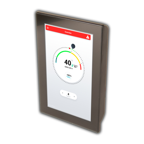
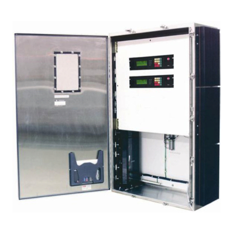
Thermon TraceNet TCM2 Installation manual

TraceNet
TM
Control
and Monitoring
System
TCM2
Installation, Start-Up,
Operating and Maintenance Guide


i
TCM2
Installation, Start-Up, Operating and Maintenance Guide
©2017 Thermon Manufacturing Company. All Rights Reserved.
This guide, as well as the firmware described in it, is furnished under license and
may only be used or copied in accordance with the terms of such license. The
information in this guide is furnished for informational use only, is subject to
change without notice, and should not be construed as a commitment by
Thermon Manufacturing Company. Thermon Manufacturing Company assumes
no responsibility or liability for any errors or inaccuracies that may appear in this
guide.
This document may not, in whole or in part, be copied, photocopied, reproduced,
translated, or reduced to any electronic medium or machine-readable form
without prior consent in writing from Thermon Manufacturing Company. This
document is subject to change without notice.
Written and designed at Thermon Manufacturing Company,
100 Thermon Drive, San Marcos, TX 78667-0609, USA
This operating guide is designed solely for use by owners of TraceNetTM TCM Series
heat tracing control systems. This firmware and operating guide is considered
proprietary and is protected by copyright. Use by others without expressed written
consent of Thermon Manufacturing Company is strictly prohibited.
©Thermon 2017

ii
Contents
1Introduction...................................................................................................................1
1.1The Panel Location..................................................................................1
1.2Initial Inspection and Handling...............................................................1
1.3The TCM2..................................................................................................3
1.4Features.....................................................................................................3
2Specifications...............................................................................................................5
Table 2.1: TCM2 Panel Specifications.............................................................5
Table 2.2: TCM2 Module Specifications..........................................................6
3Module Connections & Wiring...................................................................................9
3.1Bottom Side Connections.......................................................................9
3.2Top Side Connections...........................................................................10
4Field and Panel Wiring.............................................................................................12
4.1Heat Trace and Insulation Installation.................................................12
4.2RTD Installation and Wiring..................................................................12
4.3Power Distribution Wiring and Breakers.............................................13
4.4TraceNet Panel Wiring..........................................................................14
4.5Serial Communication Wiring...............................................................14
5Monitoring Heat Tracing Circuit Status..................................................................16
5.1The Interface...........................................................................................16
5.2Basic Navigation.....................................................................................18
5.3Alarms......................................................................................................18
5.4Trips..........................................................................................................19
6Accessing Control Settings......................................................................................22
6.1Password Protection..............................................................................22
6.2Adjusting Set-points...............................................................................22
Table 6.1: Main Menu Options.....................................................................24
7Heat Trace Control and Monitoring........................................................................27
7.1Control Method.......................................................................................27
7.2Setting the Control Method...................................................................28

iii
7.3The TCM2 in Process Sensing Applications......................................28
7.4The TCM2 in Ambient Sensing Applications......................................29
7.5Single-Circuit 3-Phase...........................................................................30
8The TCM2 Data Highway Communications..........................................................31
9System Start-Up........................................................................................................33
9.1Initial Start-Up Procedure......................................................................33
9.2Troubleshooting Tips.............................................................................33
10Maintenance...............................................................................................................34
10.1Safety Precautions.............................................................................34
11Notes...........................................................................................................................35
12Appendix A: Memory Map........................................................................................36
13Appendix B: Additional Information........................................................................41
14Appendix C: Troubleshooting Tips.........................................................................42

1
1 Introduction
The following serves as a guide and overview of the installation, startup and
operation of a TraceNet TCM2 heat tracing control and monitoring system. This
guide shall be used in conjunction with the project specific control system
drawings and any other standard installation instructions/guides provided. In the
unlikely event that a conflict or uncertainty arises, contact the Thermon
engineering support personnel assigned to this project to clarify.
1.1 The Panel Location
A wide variety of TraceNet TCM2 system configurations are possible. The TCM2
control panels are designed to operate in ambients ranging from -40°F (-40°C) to
104°F (40°C) and higher. TraceNet TCM2 heat trace control and monitoring
systems have been approved/certified for installation and operation in
ORDINARY LOCATIONS and CLASS I, DIV 2, GROUPS B, C, D, T4
HAZARDOUS LOCATIONS ONLY, Installation Category II, at altitudes up to
2000 m, and in locations where the Mains supply voltage can fluctuate up to
10%. The actual markings provided on the panel will detail the specific location
requirements for each design. The module may be used in pollution degree 2 or
better.
1.2 Initial Inspection and Handling
Upon receiving the TraceNet TCM2 control panel, it is important to confirm that
the contents of the shipping containers agree with the shipping documents and
with the purchase order. Also, it is important to check the shipped container
exterior and packing materials for any possible freight damage. Where damage is
observed, take photos and notify the carrier as well as your nearest Thermon
engineering support center before proceeding further.
After carefully removing the panel from its shipping container, move the panel to
its selected location, either by utilizing the pallet base and the securement
strapping provided (using a lift truck/fork lift in the case of large panels), or by
lifting and mounting to a wall/rack for smaller panels. Where lifting eyes are
provided on the panel, they should be used when handling.
Where the panel has external heat sinks to dissipate the heat generated by solid
state relay switching, it is recommended that a minimum of 6” (150 mm) of
All installation personnel should be properly trained and qualified to safely install,
service and program this TraceNet heat tracing control panel as well as to operate
the associated heat tracing system. Service shall only be performed by a certified
technician. Equipment is located in enclosures whose doors can only be opened
through use of a tool.

2
clearance be allowed between heat sinks and walls or other panels to minimize
heat buildup at the heat sinks.
Where heat sinks are present on adjacent panels, allow 12” (300 mm) clearance
between heat sinks for sufficient natural air movement.
Adequate door clearance for service work entry and conduit panel entries should
be anticipated when establishing the exact panel location. The panel should be
positioned such that the operator can easily access any disconnecting breakers
or fuses. When the panel is located outdoors, the panel should be located at a
sufficient height to avoid potential standing water.
Once the panel has been properly located, refer to the project specific installation
details for the recommended floor mounting as well as wall mounting details.
Once bolted in place, the panel is ready for final configuration, wiring, and site
required assembly. Note that the TCM2 control and monitoring module is
normally shipped in special packaging to minimize any undue impact stress
during shipment. It should be removed from its packaging being attentive to any
shipping damage that may have occurred during its transit.
Warning: Heat Sink Temperatures May Exceed 60°C
WHEN USED IN A HAZARDOUS LOCATION THE FOLLOWING WILL APPLY.
WARNING – EXPLOSION HAZARD – DO NOT DISCONNECT EQUIPMENT
UNLESS POWER HAS BEEN SWITCHED OFF OR THE AREA IS KNOWN TO BE
NON-HAZARDOUS
AVERTISSEMENT – RISQUE D’EXPLOSION – AVANT DE DÉCONNECTER
L’EQUIPEMENT, COUPER LE COURANT OU S’ASSURER QUE L’EMPLACEMENT
EST DÉSIGNÉ NON DANGEREUX
WARNING – EXPLOSION HAZARD – SUBSTITUTION OF COMPONENTS MAY
IMPAIR SUITABILITY FOR CLASS I, DIVISION 2
AVERTISSEMENT – RISQUE D’EXPLOSION – LA SUBSTITUTION DE
COMPASANTS PEUT RENDRE CE MATÉRIEL INACCEPTABLE POUR LES
EMPLACEMENTS DE CLASSE I, DIVISION 2

3
1.3 The TCM2
The TCM2 is a microprocessor-based temperature control and monitoring
module developed specifically for heat tracing. Designed for use exclusively in
Thermon manufactured control systems, the TCM2 module provides a complete
control solution for up to two heat tracing circuits.
1.4 Features
Features of the TCM2 module include the following
Bright Four-Line OLED Display
Resettable Minimum and Maximum Temperature Values
Alarm Functions
oHigh and Low
Temperature
oHigh and Low Current
oHigh Ground/Earth
Leakage Current
oCircuit Fault
oDamaged Temperature
Sensor
Trip Functions
oHigh Temperature
oHigh Current
oHigh Ground/Earth
Leakage Current
3-phase Current Monitoring
1
The TCM2’s four-line display, tri-color status LEDs and four-button interface offer
the operator intuitive access to the heat tracing system operating parameters
including heat trace status, all set-points, temperature data, operational control
1
Factory configurable option. See Section 7.5 for more information
Each TCM2 module is supplied with all necessary connection hardware.
Substitutions may impair protections provided by the equipment.
Figure1.1:TCM2 Control
Module

4
parameters and communication settings. Tri-color LEDs on the front of the
TCM2 module indicate module status including power, system health, alarm and
trip status on a per-circuit basis.
The TCM2 module is provided with three 24 VDC digital outputs: TRIP, ALARM
and SYS. TRIP and ALARM are configurable to be normally on or normally off.
The TCM2 is also equipped with an isolated RS-485 port capable of ModBus
ASCII or RTU communications. Over a shielded two-wire twisted-pair physical
layer, the TCM2 communicates with Thermon’s TraceNet Command system as
well as distributed control systems (DCS) at data rates up to 57600 baud.
Ethernet connectivity is available with the factory addition of a serial to Ethernet
converter.
The TCM2 contains an internal 3.15 Amp, 250 V~ fuse that is designed to be
serviced only at the factory.
The TCM2 module can be utilized in a variety of TraceNet control and monitoring
systems. Specific wiring and equipment arrangement details are provided in
drawings included within the TCM2 Series panel at the time of shipment. The
TCM2 module is also backward compatible and may be used as an upgrade
within legacy HeatChek TC Series Systems formerly utilizing a TC202a, TC201a
or TC101a control and monitoring module.
The TCM2 module is intended for installation exclusively in Thermon designed TCM2
panels. The Mains feed to the TCM2 module shall be current limited, either by a
breaker or a fuse, with a current rating no higher than 30 A. The panel is designed
such that the temperature internal to the enclosure does not exceed the maximum
operating temperature of the TCM2 module. All wiring to the unit must conform to
local electrical codes.

5
2 Specifications
TCM2 control panels are available in a variety of configurations. The table below
serves as general specification information for these control panels.
Table 2.1: TCM2 Panel Specifications
Parameter Description
Heat Trace Mains Supply 100 to 600 V~, 50/60 Hz (See Table 2.2 for Control
Module supply information)
Control Points Up to 2 Heat Tracing Circuits
Heat Trace Current See Table 2.3:MaximumHeaterCurrentThrough
EachSolidStateRelay
Temperature Inputs Up to Two per Control Point; Platinum RTDs 100 Ω
@ 32 °F (0 °C)
Temperature Control
Range -200 °F to 1112 °F (-129 °C to 600 °C)
Alarm Contact Relays 24 VDC, 200 mA
Communication RS-485 , ModBus ASCII or RTU, up to 57600 Baud
Control Methods On/Off MEC, On/Off SSR, Proportional, Ambient or
APCM
Display 4 Line, 20 Character, OLED
Relative Humidity 0 to 90% Non-Condensing
Exterior Panel Operating
Temperature -40 °F to 104 °F (-40 °C to 40 °C)
Interior Operating
Temperature -40 °F to 140 °F (-40 °C to 60 °C)
Storage Temperature -40 °F to 140 °F (-40 °C to 60 °C)
Dimensions (W x H x D) See Table 2.4

6
The table below serves as general specification information for the TCM2 control
module.
Table 2.2: TCM2 Module Specifications
Parameter Description
Mains Supply 100 to 240 V~, 50/60 Hz, Overvoltage Category II
Max. Input Current 740 mA
Power Consumption 95 VA max
Control Points Up to 2 Heat Tracing Circuits
Temperature Inputs Up to Two per Control Point; Platinum RTD’s 100 Ω
@ 32 °F (0 °C)
Temperature Control
Range -200 °F to 1112 °F (-129 °C to 600 °C)
Communication RS-485, ModBus ASCII or RTU, up to 57600 Baud
Accessory Power Output 9 W @ 24 VDC
Digital Alarm Outputs 3 x 24 VDC, 100 mA
Control Outputs 2 x 24 VDC, 100 mA or 2 x 12 VDC, 100 mA (user
selectable)
Control Methods On/Off MEC, On/Off SSR, Proportional, Ambient or
APCM
Display 4 Line, 20 Character, OLED
Operating Temperature -40 °F to 140 °F (-40 °C to 60 °C)
Storage Temperature -40 °F to 176 °F (-40 °C to 80 °C)
Dimensions (W x H x D)
4.7” x 4.65” x 3.25” (119mm x 118mm x 83mm)
Module should be mounted as seen in Figure 2.1
and include a minimum 2” (50 mm) clearance above
the module and 1.5” (38 mm) clearance below the
module.
Fi
g
ure 2.1: TCM2 Module Dimensions

7
Table 2.3: Maximum Heater Current Through Each Solid State Relay
Note: For TCM2-x, the x denotes relay count. Double-pole relay or 2 single-pole relays required for 208VAC or 240VAC to break
both legs.
1Relaysinseparateenclosurefromcontrolmodule.
2Amperagevaluesover30onlyapplytohigheramperagerelayssuchasCrydomHD60125.
360Aallowedonlywhenusing1or2relays.
Enclosure
Option
Module
Type
SSR30A
(single pole
relay)
SSR15A
(double pole
relay)
SSR30B
(single pole
relay)
SSR15B
(double pole
relay)
SSR50C
Up to 3 single
pole relays(1,2,3)
SSR30B/2R
(single pole
relay)
40°F
(4°C)
104°F
(40°C)
40°F
(4°C)
104°F
(40°C)
40°F
(4°C)
104°F
(40°C)
40°F
(4°C)
104°F
(40°C)
40°F
(4°C)
104°F
(40°C)
40°F
(4°C)
104°F
(40°C)
P2, SS2 TCM2-1 30 19 22 9 30 30 24 15 -- -- 30 25
P3, SS3 TCM2-1 30 24 24 12 30 30 24 15 -- -- 30 30
TCM2-2 30 12 19 6 30 30 24 14.75 -- -- -- --
SS3 TCM2-1 -- -- -- -- 46(1,2) 46(1,2) -- -- -- -- -- --
TCM2-2 -- -- -- -- 46(1,2) 46(1,2) -- -- -- -- -- --
SS4 TCM2-1 30 24 24 12 30 30 24 15 50/60 60/50 30 28
TCM2-2 30 24 24 12 30 30 24 15 60/50 60/50 -- --

8
Table 2.4: TCM2 System Enclosure Options
Enclosure
Option Material Type Dimensions
(inches)
Dimensions
(mm)
P2 Fiberglass 4X (IP54) 12 x 14 x 6 305 x 356 x 152
SS2 Stainless Steel 4X (IP54) 12 x 14 x 6 305 x 356 x 152
P3 Fiberglass 4X (IP54) 16 x 14 x 6 406 x 356 x 152
SS3 Stainless Steel 4X (IP54) 16 x 14 x 6 406 x 356 x 152
SS4 Stainless Steel 4X (IP54) 36 x 30 x 16 914 x 762 x 406

9
3 Module Connections
& Wiring
The TCM2 is intended for use exclusively in TraceNet TCM2 Control and
Monitoring System panels. Refer to Figures 3.1 and 3.2 for TCM2 Module
connections.
Design considerations within panel:
Control wiring is rated to 105°C
GFI test loop wires should be passed through their corresponding GFI
CT’s
Alarm digital outputs are intended to drive internal signal relays or lights
and should not be directly connected to field wiring
Care must be taken to avoid exceeding the temperature rating of the
TCM2. Refer to Table 2.3 for panel current ratings.
3.1 Bottom Side Connections
1. POWER: Mains supply input accepts 100 – 240 V~, at 50/60 Hz. L1 is
Line 1, L2 is Line 2 or Neutral, and the symbol is the protective
conductor/ground connection.
2. 24 VDC & DIGITAL OUTPUTS: A 24 VDC output is provided to power
accessories such as a serial to Ethernet converter. The output supplies
up to 9 W and is over-current protected. The Digital outputs provide
alarm functionality. Each 24 VDC output is current limited to 100 mA.
Figure3.1: Bottom-Side Connections

10
The positive legs of each output are electrically connected. The outputs
may be used to drive indicators or audible alarms, etc., or may be used to
drive relays to connect to field wiring. TRIP and ALARM are configurable
to be normally on or normally off. The TRIP output activates if either
circuit trips for any reason. This requires a manual reset either at the
module or by the remote communication. The ALARM output activates if
either circuit experiences any type of alarm. The output deactivates when
acknowledged or when the alarm condition is no longer present. The
SYS alarm is hard wired to be normally on and to activate in the event of
a CPU fault. Note: These are open collector digital outputs not dry contact
relays. They should not be connected directly in parallel or series.
Digital outputs should not be directly connected to field wiring.
3. ACCESSORY: Reserved for future developments and for entering
factory test mode when connected to the isolated RS-485 (Right Pin > D-;
Middle Pin > S; Left Pin > D+).
4. AUX IN: Provides connection for optional factory-installed externally
mounted interface buttons (See Appendix B for wiring diagram).
5. FACTORY: This port is for factory programming only.
6. COMM LED: Indicates traffic on the isolated data highway RS-485.
3.2 Top Side Connections
RTD field wiring should be shielded and the shield grounded at one end.
Ground connections are provided in the panel for this purpose.
HEATER CT1, 2 and 3: In normal 2 circuit configuration, HEATER CT1 is
used for Circuit 1, HEATER CT2 is used for Circuit 2 and HEATER CT3 is
not used. When operating as a single-circuit 3-phase controller all three
CTs are used, one on each leg of the 3-Phase heater outputs (See
Section 7.5).
GFI CT1 & 2: These are connection points for the ground/earth fault CTs.
GFITL1 & 2: These are connections for the ground/earth fault interrupt
test loop. These wires should be routed through each corresponding
ground/earth fault CT. These wires are used to pass a small amount of
Figure3.2:Top-Side Connections.

11
current (about 50 mA~) through the GFI CT to verify functionality on
command or at a user configurable interval.
CTRL OUT 1 & 2: These output signals control the power SSRs or
mechanical relays which energize the heat trace. Signal voltage defaults
to 12 VDC but can be changed to 24 VDC in the Factory Menu. Each
output is current limited to 100 mA.
REMOTE ACK: This isolated input allows acknowledgement of alarms
without opening the panel. It may be connected to a pushbutton switch or
to the contacts of a relay driven by a remote signal. The positive side
provides an isolated 5 VDC signal. When switched, the negative side
drives the diode of an opto-coupler to signal to the TCM2
acknowledgement of the alarm or trip.
RS-485 DATA HWY: D+ & D- are the differential bus lines for
communications. S is the common leg and is often connected to the
shield in a 2-wire twisted pair cable. Though this configuration is
common, ideally, S is connected to another wire within the cable and the
shield is grounded on one side only. See Section 8 for more information.

12
4 Field and Panel
Wiring
For a successful installation of a TraceNet TCM series heat tracing control and
monitoring system, a number of equally critical parts of the system must be
installed properly. Areas requiring close attention are the heat trace and
insulation, the RTD temperature sensor installation, the distribution of the field
RTD and power wiring, and the installation and routing of wiring inside the
TraceNet TCM panel.
4.1 Heat Trace and Insulation Installation
All heat trace circuits and insulation shall be installed in accordance with project
installation details provided. In addition, refer to the Electric Heat Tracing
Maintenance and Troubleshooting Guide (Thermon Form No. 20745) for general
procedures and installation tips.
4.2 RTD Installation and Wiring
RTD control sensors should generally be installed on the process lines or in
ambient (where ambient sensing is applied) in a location that is most
representative of the entire heat trace circuit. In general, it is recommended that
the sensors not be located at heat sinks such as pipe supports, pumps, and
valves as the control system response needs to be based on the majority of the
process line. The RTD control sensor location on the process piping should
follow the installation guidelines detailed in Figure 4.1.
The heat tracing system installation shall be in accordance with the electrical area
classification requirements and as well shall conform to the latest requirements as
detailed in applicable heat tracing standards, the local Electrical Code and plant
standard practices. Where conflicts arise, contact the project engineer for resolution.
If the equipment is used in a manner not specified in this Guide, protections provided
by the equipment may be impaired.

13
Figure 4.1: RTD Sensor Location
Where RTD sensors are installed on the process piping, follow the guidelines
above. In special cases where the limiting temperature sensor is to be installed
on the heater itself, it is important to recognize that an offset should be
anticipated in the trip set-point to allow for sensor reading error and overshoot.
As a general rule, field RTD wiring and power wiring should not be routed in the
same conduit or proximity in a tray as the temperature signals can become
distorted and result in improper readings.
4.3 Power Distribution Wiring and Breakers
All field power wiring materials used shall be suitable for the intended service and
shall be rated for insulation service temperatures up to and exceeding 221°F
(105°C) unless higher values are otherwise noted in project specifications.
Power supply wiring from the power transformers to the power distribution panel
and distribution wiring to the heat trace circuits shall be rated for the heat trace
use voltage or higher and shall be of a sufficiently large wire size to minimize
voltage drop. Heat trace circuit breakers should be selected based on the type of
heat trace used, the service voltage, and the circuit current draw characteristics.
It is especially important when using self-regulating trace heaters to make sure
that the circuit breaker response curve type is coordinated with the startup
characteristic of the trace heater in a cold start condition. TCM2 controller circuit
breakers should have current ratings no higher than 15 A. In addition to the
controller circuit breaker, every heat trace circuit shall be provided with a circuit
breaker as a means for disconnection. All circuit breakers shall be easily
identifiable and accessible. All distribution wiring connections should be
tightened using a torque indicating screw driver to the levels indicated in Table
4.1.
Table 4.1: Recommended Torque Values
Location of Terminals Torque Values (Typical)*
Distribution Equipment 13.2 to 15.9 in. lbs. 1.49 to 1.80 N-m

14
* Required torque values may vary depending on individual system designs and
size of terminals. Refer to project documentation for additional information.
4.4 TraceNet Panel Wiring
TraceNet TCM Series panels are configured and prewired into an integrated heat
trace control and monitoring panel. Clean terminal strips are provided to facilitate
the field wiring into the panels. Refer to the project specific panel drawings when
installing the field wiring within the panel. Anticipated field wiring is
conventionally shown by dashed lines. All field power wiring materials used shall
be suitable for the intended service and shall be rated for insulation service
temperatures of at least 221°F (105°C) unless higher values are otherwise noted
in project specifications. All TraceNet component terminal block connections
should be tightened using a torque indicating screw driver to the levels indicated
in Table 4.1.
4.5 Serial Communication Wiring
TraceNet TCM Series panels may be linked together for communications with an
RS-485 communication cable at distances up to 4000 ft (1200 m)1. In addition, a
120 Ohm termination module should be used at each end of the RS-485 network.
The recommended communication cables for use in the RS-485 network are as
given in Table 4.2.
1Maxlengthdependsonsiteconditionsandbaudrate
Protective earth/ground connection is required. Ground/earth with minimum 12 AWG
conductors to a known and proven plant ground or by grounding rods.

15
Table 4.2: Recommended RS-485 Cable Type
Cable Type Recommended
120 ohm, -20°C to +60°C (-4°F to +140°F)
22AWG FHDPE insulation PVC outer jacket
Belden 3107A or equal
120 ohm, -30°C to +80°C (-22°F to +176°F)
24AWG PE insulation PVC outer jacket
Belden 9842 or equal
120 ohm, -70°C to +200°C (-94°F to +392°F)
24AWG Teflon FEP insulation Teflon FEP outer
j
acket
Belden 89842 or equal
Note: All these products are designated as 120 ohm impedance for balanced
line communication uses.
Table of contents
Other Thermon Control System manuals
