thomann the t.mix 24.12 User manual

24.12
mixer
user manual

Musikhaus Thomann
Thomann GmbH
Hans-Thomann-Straße 1
96138 Burgebrach
Germany
Telephone: +49 (0) 9546 9223-0
E-mail: [email protected]
Internet: www.thomann.de
28.08.2018, ID: 433544

Table of contents
1 General notes............................................................................................................................ 4
1.1 Further information........................................................................................................ 4
1.2 Notational conventions................................................................................................. 4
1.3 Symbols and signal words........................................................................................... 5
2 Safety instructions................................................................................................................. 6
3 Features....................................................................................................................................... 8
4 Installation................................................................................................................................. 9
5 Connections and controls................................................................................................ 10
6 Operating................................................................................................................................. 17
6.1 Main menu...................................................................................................................... 17
6.2 Parametric Equalizer.................................................................................................... 19
6.3 Graphic Equalizer.......................................................................................................... 20
6.4 Compressor..................................................................................................................... 21
6.5 Noise Gate....................................................................................................................... 22
7 Technical specications.................................................................................................... 23
8 Plug and connection assignment................................................................................. 25
9 Cleaning.................................................................................................................................... 27
10 Protecting the environment........................................................................................... 28
Table of contents
24.12
3

1 General notes
This manual contains important instructions for the safe operation of the unit. Read
and follow the safety instructions and all other instructions. Keep the manual for
future reference. Make sure that it is available to all those using the device. If you sell
the unit please make sure that the buyer also receives this manual.
Our products are subject to a process of continuous development. Thus, they are
subject to change.
1.1 Further information
On our website (www.thomann.de) you will nd lots of further information and
details on the following points:
Download This manual is also available as PDF le for you to download.
Keyword search Use the search function in the electronic version to nd the
topics of interest for you quickly.
Online guides Our online guides provide detailed information on technical
basics and terms.
Personal
consultation
For personal consultation please contact our
technical hotline.
Service If you have any problems with the device the
customer service will gladly assist you.
1.2 Notational conventions
This manual uses the following notational conventions:
The letterings for connectors and controls are marked by square brackets and italics.
Examples: [VOLUME] control, [Mono] button.
Texts and values displayed on the device are marked by quotation marks and italics.
Examples: ‘24ch’ , ‘OFF’ .
Letterings
Displays
General notes
mixer
4

The individual steps of an instruction are numbered consecutively. The result of a
step is indented and highlighted by an arrow.
Example:
1. Switch on the device.
2. Press [Auto].
ðAutomatic operation is started.
3. Switch o the device.
1.3 Symbols and signal words
In this section you will nd an overview of the meaning of symbols and signal words
that are used in this manual.
Signal word Meaning
DANGER! This combination of symbol and signal word indicates
an immediate dangerous situation that will result in
death or serious injury if it is not avoided.
NOTICE! This combination of symbol and signal word indicates
a possible dangerous situation that can result in mate‐
rial and environmental damage if it is not avoided.
Warning signs Type of danger
Warning – high-voltage.
Warning – danger zone.
Instructions
General notes
24.12
5

2 Safety instructions
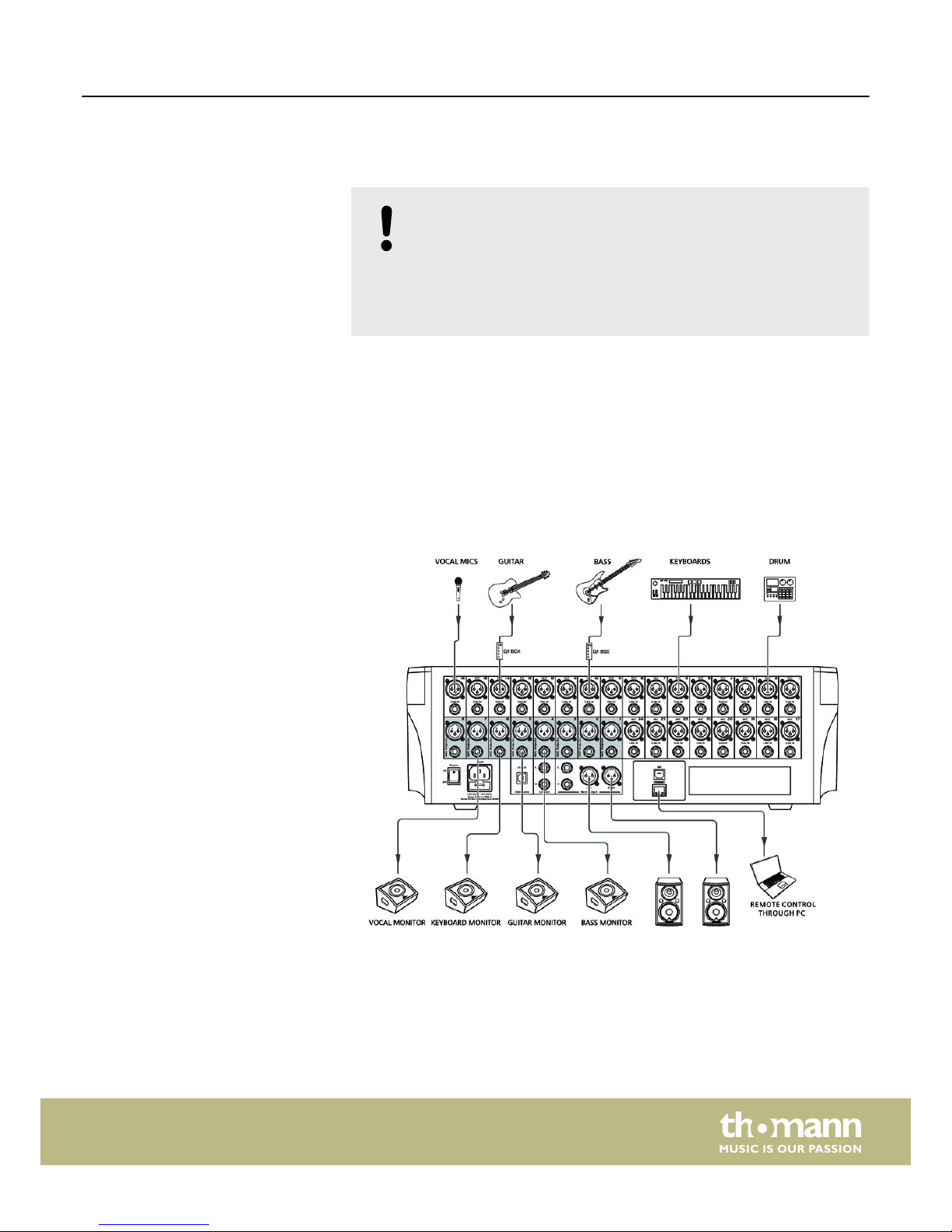
This device is intended to be used for amplication, mixing and playback of signals
from musical instruments and microphones. Use the device only as described in this
user manual. Any other use or use under other operating conditions is considered to
be improper and may result in personal injury or property damage. No liability will be
assumed for damages resulting from improper use.
This device may be used only by persons with sucient physical, sensorial, and intel‐
lectual abilities and having corresponding knowledge and experience. Other persons
may use this device only if they are supervised or instructed by a person who is
responsible for their safety.
DANGER!
Danger for children
Ensure that plastic bags, packaging, etc. are disposed of properly and
are not within reach of babies and young children. Choking hazard!
Ensure that children do not detach any small parts (e.g. knobs or the
like) from the unit. They could swallow the pieces and choke!
Never let children unattended use electrical devices.
DANGER!
Electric shock caused by high voltages inside
Within the device there are areas where high voltages may be present.
Never remove any covers.
There are no user-serviceable parts inside.
Do not use the device if covers, protectors or optical components are
missing or damaged.
DANGER!
Electric shock caused by short-circuit
Always use proper ready-made insulated mains cabling (power cord)
with a protective contact plug. Do not modify the mains cable or the
plug. Failure to do so could result in electric shock/death or re. If in
doubt, seek advice from a registered electrician.
NOTICE!
Risk of re
Do not block areas of ventilation. Do not install the device near any
direct heat source. Keep the device away from naked ames.
Intended use
Safety
Safety instructions
mixer
6

NOTICE!
Operating conditions
This device has been designed for indoor use only. To prevent damage,
never expose the device to any liquid or moisture. Avoid direct sunlight,
heavy dirt, and strong vibrations.
NOTICE!
Power supply
Before connecting the device, ensure that the input voltage (AC outlet)
matches the voltage rating of the device and that the AC outlet is pro‐
tected by a residual current circuit breaker. Failure to do so could result
in damage to the device and possibly injure the user.
Unplug the device before electrical storms occur and when it is unused
for long periods of time to reduce the risk of electric shock or re.
Safety instructions
24.12
7

3 Features
nDigital mixer
n24 × microphone and line inputs with analogue gain, designed as both XLR and
1/4" phone jacks
n2 built-in eects
n8 × AUX outputs (XLR and 1/4" jack)
n12 DCA groups that can control the volume of multiple channels with one fader
without mixing the signals down to one signal.
n1 headphones output (stereo, as 1/4" phone jack)
nNoise Gate
nCompressor
n4-band parametric EQ per channel
nReal-Time-Analysis function (RTA) for spectral analysis of the signal in a channel
nAutomix
n13 × motorized fader (100 mm)
n7" touch screen
n24 Bit/48 kHz sampling rate
niPad app for wireless remote control available (external router required)
Features
mixer
8

4 Installation
NOTICE!
Danger of short circuit
Switching on phantom power will damage the device if unbalanced XLR
cables are connected.
Only turn on phantom power when exclusively balanced XLR cables are
connected.
Unpack and carefully check that there is no transportation damage before using the
unit. Keep the equipment packaging. To fully protect the device against vibration,
dust and moisture during transportation or storage use the original packaging or
your own packaging material suitable for transport or storage, respectively.
Create all connections while the device is o. Use the shortest possible high-quality
cables for all connections. Take care when running the cables to prevent tripping
hazards.
Connection options
Installation
24.12
9

5 Connections and controls
A Settings for the inputs
B Settings for tone and signal processing
C Settings for the outputs
Overview
Connections and controls
mixer
10

1 The controls [1]…[24] adjust the input signal to the working level of the unit.
2[Sig/Clip]
The LED lights up green when a signal is present at the respective input (level > -30 dB).
The LED lights up red when the signal level is too high and distortion due to clipping occur (level > +20 dB). In this
case, reduce the level with the [Mic/Line] control.
3[Pan]
Rotary control for adjusting the signal within the stereo panorama.
4[Automix]
Reduces the volume of the microphone when not in use.
5[Digital / In/Out]
Switches between digital input and output when the digital module is installed.
6[48V DC]
Enables the phantom power. The button lights up when the phantom power is turned on.
The phantom power leads to damage to the device if unbalanced cables are connected. Only switch on phantom
power while exclusively balanced cables are connected.
Front panel A and B
Connections and controls
24.12
11

7[Route / To Main]
Allows you to assign an input channel to the main channel.
8[Gate]
Opens the ‘Gate’ page for Noise Gate settings.
9[Assign]
Opens the ‘Assign’ page for the assignments of input channels to buses.
10 [Comp]
Opens the ‘Comp’ page for Compressor settings.
11 [PEQ]
Opens the ‘PEQ’ page for parametric EQ settings.
12 [Channel]
Opens the ‘Channel’ page for a summary of the settings of the currently selected channel, bus, or DCA group.
13 7" touch screen
14 [FX Exit]
Selects the eects bus FX 1 or FX2 to perform tone control and assignment to outputs.
15 [Routing]
Allows the assignment to outputs for the respective bus.
16 [System]
Opens the system menu for editing presets.
17 [Load / Save]
Opens the menus for loading or saving presets.
18 [Enter / (TAP)]
Conrms settings in the menu. On pages ‘FX1’ and ‘FX2’ you can use this button to enter the setting for the delay
function in time with the music.
19 [Parameter Adjust]
Control to set the main parameter of the currently selected eect.
Pressing [Up], [Down], [Left] and [Right] lets you navigate on the display pages.
20 [Mixer]
Opens the ‘Mixer’ page for channel settings.
21 [Copy]
Copies the channel settings for another channel.
22 [Control Room]
Volume control for the control room output
23 [Phones]
Volume control for headphone output
Connections and controls
mixer
12

24 [USB Lamp]
USB port for supplying power to accessories, such as a gooseneck lamp
25 [Main Out]
Level meter of main channel or solo channel. By default, the level of the main channel is displayed when the
[Solo / Meters] button is not pressed.
26 [Solo / Meters]
Toggles the level meter [Main Out] between Main and Solo.
27 [PFL]
Switches the Control Room output between the modes Pre Fader Listen (PFL) and After Fader Listen (AFL). This can
be used to monitor a signal either as it is present at the input or as it sounds aected by the tone and volume
controls.
Connections and controls
24.12
13

28 [S Clear]
Cancels the solo mode for all input channels and buses. The button lights orange when at least one channel or bus
is operating in Solo mode.
29 [M Clear]
Unmutes all input channels and buses.
30 [Stereo / Link]
Input channels 1…24 and buses AUX 1…AUX 8 can each be paired as stereo channels. When pairing is on, the
button lights up blue.
31 [Name]
Allows the renaming of a channel.
32 [1 – 12], [13 – 24]
Selection buttons for channels
33 [Solo]
Assigns the currently selected input channel to the solo bus. The button lights up when the input channel has
been assigned.
34 [Mute]
Mutes or unmutes the respective channel.
35 [Select]
Selects the respective channel to perform tone control and assignment to outputs.
Front panel C
Connections and controls
mixer
14

36 [FX Mute]
Mutes or unmutes eects bus FX1 or FX2.
37 [DCA Clear]
Cancels the selection of DCA groups.
38 [DCA Set]
Conrmation button for setting up DCA groups that can control the volume of multiple channels with one fader
without mixing the signals down to one signal.
39 [RTA]
Opens the ‘RTA’ page (Real-time analysis), presents a spectral analysis of the signal in the selected channel.
40 [GEQ]
Opens the ‘GEQ’ page for graphic EQ settings.
41 [Select / Main]
Assigns the currently selected input channel to the output bus Main.
42 [Meters]
Opens the ‘Meters’ page which shows the levels of all input and output channels at a glance.
43 [DCA groups / 1 – 12]
Selection buttons for DCA groups
44 Motor fader for adjusting the the main output volume
45 [Talkback]
Opens the ‘Talk Back’ page where settings for the device's Talkback feature can be made. This feature is often used
to make announcements from the console operator to the musicians on stage. To this, connect a microphone to
input 24. Channel 24 can be assigned to the output channel Main or to one of the channels AUX1…AUX8. In ‘PTT’
mode, you have to keep the [Talkback] button pressed during the announcement. In ‘ON/OFF’ mode, you have to
press [Talkback] before and after the announcement.
46 [Levels / Aux 1 – 8/FX 1– 2]
Selection button for the AUX and FX buses.
47 Motor fader to adjust the volume of the currently selected channel, bus or DCA group.
48 [Sends on Faders/ Aux 1 – 8/FX 1– 2]
Allows the assignment to outputs for the respective bus.
49 Digital channel label
Connections and controls
24.12
15

50 [Mic 1]…[Mic 24]
Mic level inputs, designed as XLR sockets.
51 [Line In 1]…[Line In 24]
Line level inputs, designed as 1/4" phone jacks.
52 [AUX Outputs 1]…[AUX Outputs 8]
AUX outputs 1…8, designed as XLR sockets.
53 [AUX Outputs 1]…[AUX Outputs 8]
AUX outputs 1…8, designed as 1/4" phone jack (mono, balanced)
54 [Ethernet]
RJ45 socket for the integration of the device into a local area network (LAN) or for rmware updates
55 [USB]
The USB port is used to exchange data with a connected PC, for example to transfer individual settings from and to
the computer.
56 [Main Output]
Master output for connecting an amplier or active speaker, designed as XLR sockets and 1/4" jacks (balanced) for
left and right channels.
57 [Ctrl Out L], [Ctrl Out R]
Control room output, designed with separate 1/4" jacks (balanced) for left and right channels.
58 [USB Audio]
USB port for feeding in digital audio signals or for digital output of the sum signal, unaected by the master fader.
59 [Input]
IEC chassis plug for operating voltage supply with fuse holder
Should the fuse have blown, disconnect the unit from the power supply and replace the fuse with a new fuse of
the same type.
60 [Power]
Main switch. Turns the device on and o.
Rear panel
Connections and controls
mixer
16

6 Operating
6.1 Main menu
In the main menu, important settings are directly accessible.
1. Press [System].
ðThe main menu appears on the display.
2. Use the display to select, set values, and navigate the menu.
The table below shows on overview of the available menus.
Menu item Meaning
‘Assign / C Strip’ Tapping the ‘Assign / C Strip’ button switches between ‘Assign’ and ‘C Strip’ function.
‘Assign’ Assigning the currently selected input channel and FX to the possible buses.
‘Main’ Assigning the channel to the Main bus. When assigned, the button lights blue.
‘AUX1-4’ Displays the status of the respective channels ‘AUX1’ , ‘AUX2’ , ‘AUX3’ , ‘AUX4’ .
‘AUX5-8’ Displays the status of the respective channels ‘AUX5’ , ‘AUX6’ , ‘AUX7’ , ‘AUX8’ .
‘Sends’ Sends the selected channel on ‘AUX1’ …‘AUX4’ or ‘AUX5’ …‘AUX8’ . Allows pre / post switching
of ‘AUX1’ …‘AUX4’ or ‘AUX5’ …‘AUX8’ .
‘Phase / INV’ Phase inversion of the selected channel.
‘INV’ : the phase is inverted.
‘PHASE’ : the phase is not inverted.
‘Select Channel’ Selection of all available channels for editing
‘Load’ Loads a conguration.
‘Copy’ Copies a conguration.
‘Save’ Saves a conguration.
‘Link’ Links the selected channel to the adjacent channel. On this, you can only link the odd-num‐
bered channels to the even-numbered channels, not vice versa.
‘C Strip’ Opens the settings for the input channels and for the output channels.
‘Gate / Comp’ Tapping the ‘Gate / Comp’ button switches between ‘Gate’ and ‘Comp’ function.
‘Gate’ Opens the settings for the channel-wise switchable noise gate.
‘Comp’ Opens the settings for the channel-wise switchable compressor.
‘PEQ / GEQ’ Tapping the ‘PEQ / GEQ’ button switches between ‘PEQ’ and ‘GEQ’ function.
‘PEQ’ Opens the settings for the parametric equalizer.
‘GEQ’ Opens the settings for the graphic equalizer.
‘FX 1 / FX 2’ Tapping the ‘FX 1 / FX 2’ button switches between ‘FX 1’ and ‘FX 2’ function.
Operating
24.12
17

Menu item Meaning
‘FX 1’ Selecting and setting the eect type for the rst eects unit
‘FX 2’ Selecting and setting the eect type for the second eects unit.
‘System / Routing’ Tapping the ‘System / Routing’ button switches between ‘System’ and ‘Routing’ function.
‘System’ Displays information about the hardware and software revision status and allows the device to
be reset to the factory defaults.
‘Routing’ Assigning the individual input channels to the currently selected bus.
‘DCA / Full Mix’ Tapping the ‘DCA / Full Mix’ button switches between ‘DCA’ and ‘Full Mix’ function.
‘DCA’ Assigning channels to DCAs (Digitally Controlled Amplier) to collectively change the level of
assigned channels.
‘Full Mix’ Displays all available channels for a complete overview of the entire mixer.
‘Meters / Mixer’ Tapping the ‘Meters / Mixer’ button switches between ‘Meters’ and ‘Mixer’ function.
‘Meters’ Overview of the level of all available channels
‘Mixer’ The ‘Mixer’ windows displays 8 channels at the same time. Tapping the ‘Bank Left’ or ‘Bank
Right’ buttons calls up the previous or next 8 channels.
Operating
mixer
18

6.2 Parametric Equalizer
For each input channel and each output channel, a parametric equalizer with four
frequency bands plus high-pass and low-pass lters can be switched on.
1. Tap the ‘PEQ / GEQ’ button to change to the ‘PEQ’ function.
2. For presetting, press the selection buttons [1-12] or [13-24] for the channels or
the selection button [AUX 1-8 FX 1-2] for the AUX and FX buses. Then use [1/13]
…[12/24] to select the desired input channel, output channel or FX bus.
Alternatively: Tap on the ‘Select Channel’ button and select the desired input
channel or output channel on the display surface. Conrm the selection with
‘Enter’ .
ðThe button for the selected input channel or output channel lights up blue.
The desired input channel or output channel is shown in the display.
3. Tap on ‘EQ1’ , ‘EQ2’ , ‘EQ3’ , ‘EQ4’ to select the frequency band.
ðThe selected frequency band lights up.
4. Tap ‘Type’ to select the type of lter.
5. Tap ‘Frequency HPF’ or ‘Frequency LPF’ to ne-tune the high-pass or low-pass
lter.
6. Adjust the desired values by moving the slider on the display.
Alternatively: Use the rotary control [Parameter Adjust] to set the desired
values.
7. Save the settings with ‘Save’ .
You can save up to 48 individual settings.
The ‘Flat EQ’ button can be used to cancel the settings made. The frequency
response is then back in the initial state.
The ‘ON/OFF’ can be used to turn the EQ on of o. By default, the EQ is turned on.
Option Selection range Meaning
‘Frequency HPF’ 20.6 Hz – 20.0 kHz High-pass lter frequency
‘Type’ Bypass, BW6, BS6, BW12, BS12,
LR12, BW18, BS18, BW24,
BS24, LR24, BW30, BS30,
BW36, BS36, LR36, BW42,
BS42, BW48, BS48, LR48
Type and slope rate of the lter
‘Low-pass lter frequency’ 20.0 kHz – 20.6 Hz Low-pass lter frequency
‘Type’ Bypass, BW6, BS6, BW12, BS12,
LR12, BW18, BS18, BW24,
BS24, LR24, BW30, BS30,
BW36, BS36, LR36, BW42,
BS42, BW48, BS48, LR48
Type and slope rate of the lter
‘Frequency EQ 1–4’ 20.6 Hz – 20.0 kHz Frequency of EQ bands 1–4.
Operating
24.12
19

Option Selection range Meaning
‘Type’ Hi-Shelf, Lo-Shelf Filter type
‘Q’ 0.4 – 24 Q shape of EQ band
‘Gain’ –24 dB – +24 dB Boost / cut
6.3 Graphic Equalizer
For the outputs MAIN and AUX, a 31-band equalizer can be switched on.
1. Tap the ‘PEQ / GEQ’ button to change to the ‘GEQ’ function.
2. For presetting, press the selection button [AUX 1-8 FX 1-2] for the AUX and FX
buses. Then use [1/13] …[8/20] to select the desired output channel.
Alternatively: Tap on the ‘Select Channel’ button and select the desired output
channel on the display surface. Conrm the selection with ‘Enter’ .
ðThe button for the selected output channel lights up blue. The desired
output channel is shown in the display.
3. Use the arrow buttons ‘Left’ and ‘Right’ to select the band for which you want
to adjust the graphic EQ.
ðA purple bar indicates the selected band.
4. Move the purple bar by tapping on it with your nger or using the arrow but‐
tons ‘Up’ and ‘Down’ to make the desired setting.
Alternatively: Use the rotary control [Parameter Adjust] to set the desired
values.
5. Save the settings with ‘Save’ .
You can save up to 48 individual settings.
The ‘Flat EQ’ button can be used to cancel the settings made. The frequency
response is then back in the initial state (at).
The ‘ON/OFF’ button can be used to turn the EQ on or o. By default, the EQ is
turned on.
Operating
mixer
20
Table of contents
Other thomann Mixer manuals

thomann
thomann MicroMix 2 USB User manual

thomann
thomann The t.mix 16.4 User manual

thomann
thomann USB Mix 4 User manual

thomann
thomann t.mix Rackmix 821 FX User manual

thomann
thomann Fun Generation PM-6 User manual

thomann
thomann ZM 4 User manual

thomann
thomann the t.mix 401-USB User manual

thomann
thomann the t.mix Source Mix 52R User manual

thomann
thomann fun generation USB Mix 3 User manual

thomann
thomann the t.mix 402-USB Play User manual