0008DJL-GBEN 9
3.6 Combustion air supply & flue system
The air heater may be installed as a balanced flue
(Type C) heater requiring both a combustion air
inlet duct and a flue pipe or as a power vented
(Type B) heater, which requires only a flue pipe
exhausting to outdoors. All products of combustion
must be flued to outdoor atmosphere.
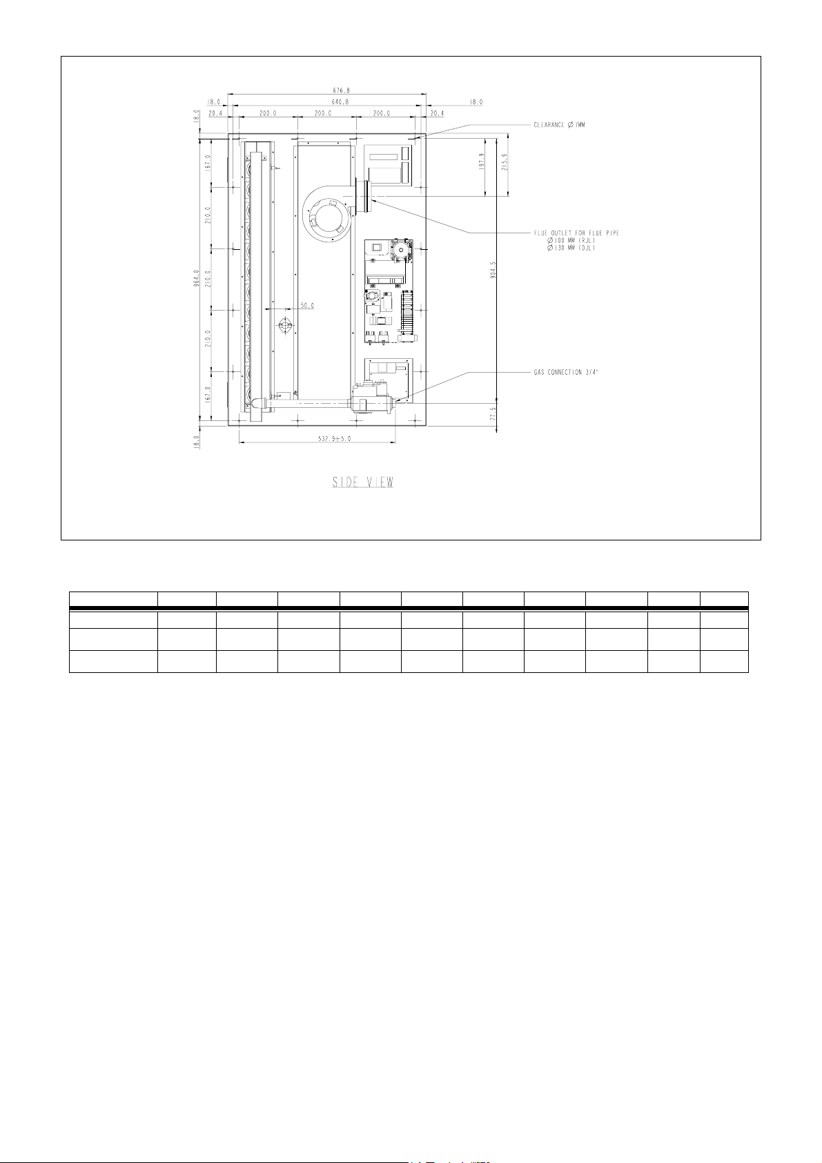
Figure 6 : Combustion air and flue pipe sockets
Each heater installed as a type B appliance must be
fitted with an individual flue pipe and the combustion
air inlet socket (IP20) (1). Each heater installed as a
type C appliance must be fitted with an individual
combustion air/flue pipe system. Only systems
specified by the air heater manufacturer may be used.
Common flue and combustion air systems must not be
used.
IMPORTANT: The flue must be installed in accordance
with national and local regulations. Failure to provide
proper fluing could result in death, serious injury
and/or property damage. The air heater must be
installed with a flue to the outside of the building.
Safe operation of any power vented gas apparatus
requires a properly operating flue system, correct
provision for combustion air, and regular maintenance
and inspection.
(1) dia 80 = PN 68 1751201 (EURO-C 4011/15 DJL)
dia 100=PN 02 250090(EURO-C 4018 & 4030 DJL )
dia130 = PN 02 25094 (EURO-C 4036 & 4100 DJL )
3.6.1 Flues for power vented installations
(Type B appliances)
If the air heater is to be installed as a type B appliance,
air for combustion will be taken from within the space
where the heater is installed. Ensure that an adequate
air supply for combustion and ventilation is provided
within the building in accordance with the regulations
& rules in force.
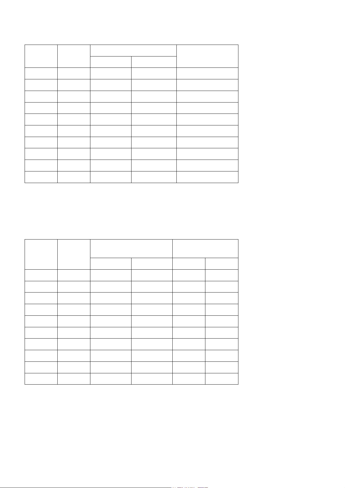
Table 4 shows flue pipe sizes and maximum vent
lengths. The minimum flue length is 0.5 metres.
Table 4 Flue pipe diameters & maximum lengths
Single wall flue pipes are required. All joints must be
sealed to prevent products of combustion from leaking
into the building. An approved flue terminal is required.
If the flue passes through a combustible element of
the building it must be enclosed by a sleeve of non-
combustible material and separated from the sleeve by
at least a 25 mm air break. The temperature of any
combustible material near to the flue must not exceed
65 °C when the heater is in operation.
The flue must be at least 50 mm away from any
combustible material.
Single wall flue pipe exposed to cold air or run through
unheated areas must be insulated. Where
condensation is unavoidable, provision must be made
for the condensation to flow freely to a point to which
it can be released, i.e. a drain or gully.
The condensation drain from the flue must be
constructed from non-corrodible material not less than
20 mm diameter. Copper or copper-based alloys must
not be used for condensation drains.
3.6.2 Combustion air inlet pipe & flue pipe for
balanced flue installation (Type C appliances)
Balanced flue air heaters are designed to be fitted with
a combustion air inlet duct that obtains outdoor air
and a flue pipe that exhausts flue products to
outdoors.
Air heaters if fitted with a power venter permitting
either a vertical or horizontal combustion air inlet/flue
pipe system. The heaters must be installed with a
concentric vertical or horizontal flue/air inlet. The
heaters are only approved for use when installed with
the appropriate approved concentric vent terminal. See
table 5.
Both the flue and combustion air pipes must be
sealed. Use gasket sealed seamless aluminum pipe or
equivalent.
Model 40.. DJL 11
15 18
24,30 36,47
60,72,100
Heater socket & mm
pipe dia 80 100 130
Maximum straight m
length 7.5
Equivalent length m
of 90° elbow 1.5