THOMSON VS360 User manual

VS 360
VS 460
User manual
Manuel d’utilisation
Bedienungsanleitung
Manuale di utilizzazione
Manual de utilización
Gebruiksaanwijzing
Návod k použití
Instrukcja obsługi
Használati kézikönyv
cover VS360/460 - 9 langues 11/07/06 19:55 Page 1 (PANTONE 405 CV film)

VS 360/460
VIDEO IN
REMOTE
OUT
2,4Ghz
2
1
4
6
5
IR
B
3
4
1 2
A
Transmitter Receiver
Receiver
6
A
5
7
B
A
VS 360
VS 460
cover VS360/460 - 9 langues 11/07/06 19:55 Page 2 (Noir/Process Black film)

1
Wireless video transmitter
Precautions
Safety
• This equipment contains heat sensitive components. Maximum ambient temperature
must not exceed 35° Celsius.
•Humidity in rooms where this equipment is situated must not exceed a hygrometric level
of 85%. If you have to use your equipment outside, avoid exposing it to rain water or
to splashes.The transition from a cold environment to a hot one may cause condensation.
Allow it to dry by itself before re-starting the equipment.
• In the event of prolonged absence, switch off the equipment by means of the on/off
switch. Even when switched off, certain components remain live. In order to insulate it
completely you must remove the plug from the main electricity supply.
• In the event of an electrical storm, it is advisable to disconnect the equipment from the
electricity supply so as to avoid potentially damaging electrical or electromagnetic surges.To
this end, make sure that the mains plug is easily accessible for disconnection.
•Disconnect the equipment immediately if you detect a smell of burning or smoke. Under
no circumstances must you open the equipment yourself; you run the risk of electrocution.
Maintenance
• Clean the equipment with a soft cloth and a neutral detergent.The use of solvents, abrasive
products or alcohol-based products is likely to damage the equipment.
Regulations
• This equipment must only be installed inside. Its use is restricted to private radio
transmission. Connection to a public or independent network, or to an outside aerial
is prohibited.
Under no circumstances should this appliance be put to industrial use. It is designed solely for
domestic operation.
THOMSON disclaims all responsibility in the event of use that does not comply with the present
instructions.
en
VS 360/460 - 9 langues 11/07/06 19:57 Page 1

2
Principles of operation
LIVING ROOM BEDROOM
Transmitter Receiver
Remote control for
video recorder,
satellite receiver,…or
universal remote
control.
Magnétoscope,
Récepteur satellite, ...
VS 360/460 - 9 langues 11/07/06 19:57 Page 2

3
What is this equipment for?
The Video Sender VS 360/460 permits the relay of an Audio-Video signal from your main
set-up to a second television set located in another room and equipped with a scart connection
(or RCA/Cinch).The main set-up is the place in which you have chosen to install the majority
of your equipment (television set, video recorder, satellite receiver, DVD player,..) you can
operate the units from the room with the second television set by using their remote controls,
or with a universal remote control.
You can play and hear music if you connect the transmitter to a suitable outlet (AUDIO OUT),
and the receiver to an amplifier (AUDIO IN) placed in another room. For the link-up you will
need to obtain 1 cinch/cinch cable (not supplied with equipment).
If you already have a Thomson plasma screen monitor or video projector, the Video Sender will
ease your placing of these items where you most want them to be, thanks to eliminating all
problems related to long cable runs.
M
E
N
U
E
N
T
E
R
C
A
N
C
E
L
SELECT
POWER
STATUS
ON
/
STANDBY
SOURCE
AUTO
ADJUST
PCCARD
ACCESS
DVD player
Plasma screen monitor
Television set
Video recorder
Camcorder
Video disc player
Satellite/Cable receiver and
decoder Video projector
A/V Amplifier
en
VS 360/460 - 9 langues 11/07/06 19:57 Page 3

4
Installation of transmitter
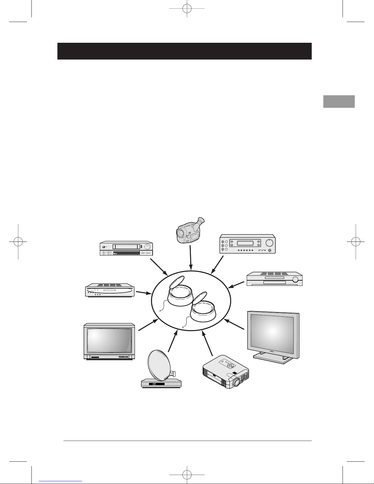
1. Place the transmitter (1) near the source equipment (VCR player, DVD player, etc.) from
which you want to transmit video or audio output, and connect it with the two cords (2 A
and 2 B) making sure you respect the color coding of the 3 cinch plugs (red and white for
audio, yellow for video). Connect the TV set to a suitable outlet from the VCR player or
DVD player (AV1).
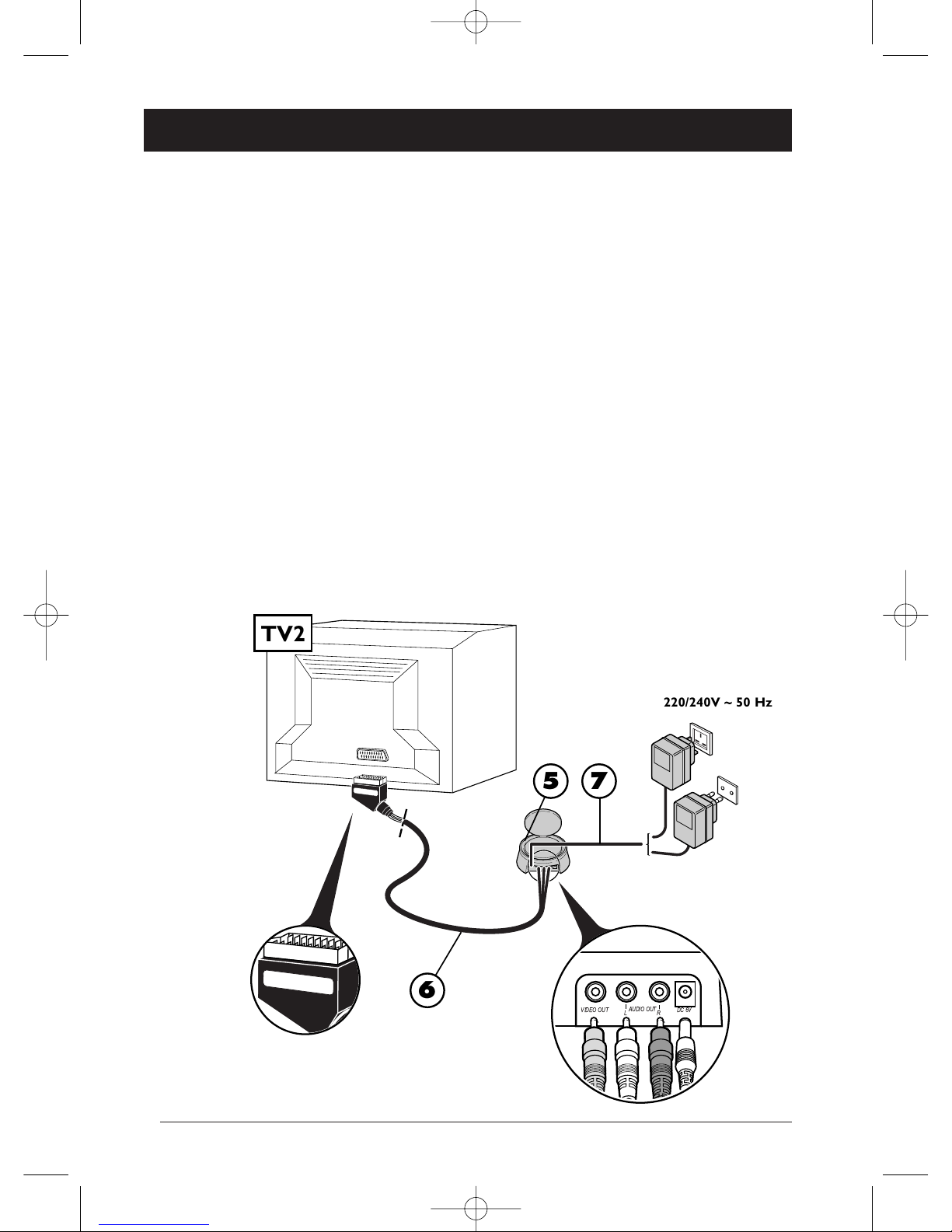
Obtain a (non-supplied) SCART-TV set connector and connect the TV set to the 2B adapter
already connected to theVCR player or DVD player as shown on Page 5 (see item marked *
on Page 5).
2. Fit the mains supply lead (3) to the transmitter and plug it into a 220/240V ~ 50 Hz
mains power supply.
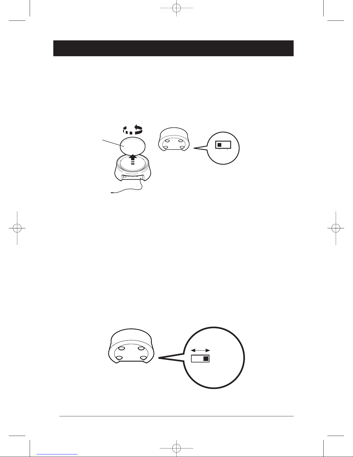
3. Carefully extend the antenna of the transmitter (1) and orient it towards the room where
your second TV set (TV2) is located. Circular antennas must be oriented so that the surfaces
with inscriptions are face to face. Turn on (position ON) the transmitter and receiver, using
the ON/OFF switch located on its lower side. Place the channel selectors of the transmitter
and the receiver on the same channel (same letter).
4. Fit the lead (4) following these stages:
- connect the jack plug to the IR EXTEND socket,
- unwind the lead and place one cell near the infrared window of the unit to be operated
(video recorder or other),
- after installing the receiver (see Pages 6 and 7), ask someone to use the remote control of
that equipment item to be controlled from the room where the second (TV2) is located,
- by moving the cell around in front of the unit to be operated you will find the location that
permits its control from the other room.You must fix the cell in that position. Usually, this
will be a more or less large, transparent area located on the front of the unit.
5. Remove the protective self-adhesive film from the infrared cell of cord (4) and affix it to the
infrared-sensitive panel of the equipment to be remote controlled.The cordon has 3 cells in
order to let you play video and audio from 3 equipment items connected to the (TV1) set
(see Diagram 2on Page 10).
VS 360/460 - 9 langues 11/07/06 19:57 Page 4

5
AUDIOIN DC12VVIDEOINIROUT LEFT RIGHT
DC 6V IR EXTEND
AV EXTEND
AUDIO IN
DC 6V VIDEO IN IR EXTENDLR
AUDIOIN
DC6V VIDEOIN IR EXTENDLR
2
1 3
4
TV1
*A
B
VS 360
en
220/240V ~ 50 Hz
UNITED-
KINGDOM -
EIRE
CONTINENTAL
EUROPE
VS 360/460 - 9 langues 11/07/06 19:57 Page 5

6
Installation of receiver
1. Place the receiver (5) on, or near, the second television set.
2. Connect the receiver (5) to the second television set using the lead (6) following the same
instructions as for the transmitter.
3. Extend the antenna on the receiver (5) and orient it toward the main TV set (TV1). Circular
antennas must be oriented so that the surfaces with inscriptions are face to face.
4. Fit the mains supply lead (7) to the receiver and plug it into a 220/240 V ~ 50 Hz mains
power supply.
! THE ANTENNA allows you to transmit and receive audio and video signals over a maximum range
of 30 meters in free air environments. Inside a typical lodgment the range will be less because of signal
attenuation by building material absorption.
! THE FLEXIBLE ANTENNA permits the control of the unit whose pictures you wish to see in the
room containing the second television set (TV2).
AUDIOIN DC 6VVIDEOINIROUT LEFT RIGHT
Receiver
Receiver
AUDIO OUT
L R DC 6VVIDEO OUT
6
TV2
57
220/240V ~ 50 Hz
UNITED-
KINGDOM -
EIRE
CONTINENTAL
EUROPE
VS 360/460 - 9 langues 11/07/06 19:57 Page 6

7
Instructions for use
1. Switch on the transmitter (1) and the receiver (5) by switching their ON/OFF buttons to
the ON position.
2. Make sure that the transmitter and the receiver are set to the same channel by
checking the position of the selectors located under the casing.They must be set
to the same channel (same letter).
3. Switch on your equipment (television sets, video recorders ...) in both rooms.
4. Using the remote control of the unit whose pictures you wish to see, and from the room
containing the second television set (TV2), select the channels or video functions (or others)
according to the unit you are controlling.
AL
Special operating details:
•No picture on TV2? If you fail to obtain the desired picture on the second television set TV2,
select the AV socket, to which the receiver (5) is connected, using the television’s remote control.
•Using a decoder (in France: Canal +,TPS, etc.) on your TV2? To have clear images on your
second TV set (TV2), output from the decoder must pass through aVCR player, placed in (AV2)
mode or set to the channel number assigned for the encrypted TV channel.
•Use of a monitor? If your second television set does not have a connection for an outside aerial
(terrestrial reception), or if it is a monitor, you will be able to see the channels in the room
containing the second television set by selecting those of the video recorder with its remote control.
•The picture is scrambled? The running of certain equipment (micro-wave ovens, digital
telephone DECT, un-shielded acoustic loudspeakers, etc ...) may interfere with signal transmission.
Ensure that they are kept away from the transmitter and the receiver or switch them off.
Make sure that you point the
remote control directly at the
receiver’s (5) infrared window
AUDIO IN DC 6VVIDEO INIR OUT LEFT RIGHT
Receiver
en
VS 360/460 - 9 langues 11/07/06 19:57 Page 7

8
Improvement of picture and sound
You will obtain optimal service operation of your Video Sender by correctly orienting
the antennae (A). However, reflected signals or other signal degrading factors can affect good
quality signal transmission. In this case, readjust antennae positions or slightly move the
transmitter or receiver until you get crystal clear reception.
If no picture is obtained,
check that the transmitter and the receiver have not been installed in the reverse order (each
unit corresponds either to the input or to the output of the Audio-Video signal). Check that
they have been properly connected and that they are switched on (ON position). Ensure that
the channel selector is set to the same letter on both units.
If transmission is blurred or scrambled,
choose another channel but make sure that it is identical on both units.
AUDIO IN
DC 6V VIDEO IN IR EXTENDLR
ON OFF
Transmitter / Receiver
(A)
a, b, c, d
Transmitter / Receiver
VS 360/460 - 9 langues 11/07/06 19:57 Page 8

9
Relay of pictures from several units
If you have several equipment items (VCR player, satellite receiver, DVD player, etc.) in your
main equipment room and want to transmit and receive audio and video signals to a second TV
set, connect your equipment items as shown in the Diagrams on following pages. Usually, the
units are connected in series, the last unit having a free scart connection that you can use for
the connection of the transmitter.
!These diagrams represent some connection possibilities the operation of which depends on the type of
unit, its sockets and the signals it produces.There exist other connections that you might perhaps wish
to try if diagrams 1 to 3 here are not satisfactory. If this is the case, ask your dealer for assistance.
!As a general rule, remember to switch off units not in use. Also, refer to the manufacturers’ instructions
to see if there are any particularities regarding connection or use. Certain units may need to have their
input scart connection “programmed”.
!In all cases the transmitter must be connected to a scart connection that produces an Audio-Video
signal Out. Refer to the manufacturer’s instructions for confirmation of this.
en
VS 360/460 - 9 langues 11/07/06 19:57 Page 9

10
General information on connections...
AUDIOIN DC6VVIDEOINIROUT LEFT RIGHT
1
32
VCR
AV output
Audio amplifier
DVD
SAT
Transmitter
AUDIOIN DC 6VVIDEOINIR OUT LEFT RIGHT
TV1
TV1
VCR
DVD
SAT
Transmitter
Satellite or Cable decoder
(Canal+, Canal Sat,TPS, Premiere,Telepiu,Via Digital…)
VCR
AV1
AV2
AUDIO
AV1
AV2
Transmitter
Power supply: 6V DC
VS 360/460 : 4 channels (A : 2.414 GHz - B : 2.432 GHz - C : 2.450 GHz - D : 2.468 GHz)
VS 360U/460U : 4 channels (A : 2.414 GHz - B : 2.432 GHz - C : 2.450 GHz - D : 2.468 GHz)
VS 360SP/460SP : 3 channels (A : 2.432 GHz - B : 2.450 GHz - C : 2.468 GHz)
Remote control return: 433,92 MHz
Transmitter power: 10 mW
Technical characteristics
VS 360/460 - 9 langues 11/07/06 19:57 Page 10

1
Transmetteur vidéo sans fil
Précautions
Sécurité
•Les composants de cet appareil sont sensibles à la chaleur. La température maximale
ambiante ne doit pas dépasser 35° Celsius.
•L’humidité des locaux où est placé l’appareil ne doit pas dépasser un taux hygrométrique
de 85%. Evitez de l’exposer à l’eau de pluie ou aux éclaboussures. Le passage d’une
atmosphère froide à une ambiance chaude peut provoquer de la condensation. Laissez-la
disparaître d’elle-même avant de remettre l’appareil en marche.
• En cas d’absence prolongée, éteignez l’appareil avec l’interrupteur marche/arrêt. Même à
l’arrêt, certains composants restent en contact avec le réseau électrique. Pour l’isoler
complètement vous devez débrancher la fiche d’alimentation de la prise secteur.
• En cas d’orage, il est recommandé d’isoler l’appareil du réseau électrique afin de ne pas le
soumettre à des surcharges électriques ou électromagnétiques qui peuvent l’endommager.
A cette fin, laissez la fiche secteur accessible pour le débrancher.
•Débranchez immédiatement l’appareil si vous constatez qu’il dégage une odeur de brûlé
ou de la fumée.En aucun cas vous ne devez ouvrir l’appareil vous-même, vous risquez
l’électrocution.
Entretien
• Nettoyez l’appareil avec un chiffon doux et un détergent neutre. L’utilisation de solvants, de
produits abrasifs ou de produits à base d’alcool risque d’endommager l’appareil.
Réglementation
• Cet appareil ne doit être installé qu'à l'intérieur d'un local. Son utilisation est restreinte aux
transmissions radioélectriques privées. Le branchement à un réseau public ou indépendant
ou à une antenne extérieure est interdit.
Cet appareil ne doit en aucun cas être utilisé à des fins commerciales. Il est uniquement prévu
pour un usage domestique.
THOMSON dégage sa responsabilité en cas d’utilisation non conforme aux indications de cette notice.
fr
VS 360/460 - 9 langues 11/07/06 19:57 Page 1

2
Principes de fonctionnement
SALON CHAMBRE
Transmitter
(Emetteur) Receiver
(Récepteur)
Télécommande du
magnétoscope,
récepteur satellite...
ou télécommande
universelle.
Magnétoscope,
Récepteur satellite, ...
VS 360/460 - 9 langues 11/07/06 19:57 Page 2

3
A quoi sert cet appareil ?
Le Video Sender VS 360/460 permet de diffuser un signal Audio-Video à partir de votre
installation principale vers un second téléviseur installé dans une autre pièce et équipé d’une
prise péritélévision (ou RCA/Cinch). L’installation principale est l’endroit où vous avez regroupé
la plupart de vos appareils (téléviseur, magnétoscope, récepteur satellite, lecteur DVD, ...).Vous
pourrez commander les appareils depuis la pièce où se trouve le second téléviseur à l’aide de
leurs télécommandes, ou avec une télécommande universelle.
La diffusion de musique est possible si vous raccordez l’émetteur à une source (AUDIO OUT) et
le récepteur à un amplificateur (AUDIO IN) dans une autre pièce. Dans ce cas vous devrez vous
procurer 1 câble cinch / cinch non fourni.
Si vous possédez un moniteur plasma ou un projecteur vidéo Thomson, le Video Sender vous
facilitera leur implantation à l’endroit désiré grâce à l’élimination des problèmes liés à la
longueur des câbles de connexions.
M
E
N
U
E
N
T
E
R
C
A
N
C
E
L
SELECT
POWER
STATUS
ON
/
STANDBY
SOURCE
AUTO
ADJUST
PCCARD
ACCESS
DVD
Moniteur plasma
TV
Magnétoscope
Camescope
Lecteur Video-disc
Récepteur et décodeur
Satellite/Câble Vidéo projecteur
Amplificateur A/V
fr
VS 360/460 - 9 langues 11/07/06 19:57 Page 3

4
Installation de l’émetteur
1. Placez l’émetteur (1) à proximité de l’appareil (magnétoscope, lecteur DVD…) dont vous
souhaitez diffuser les images et le son et raccordez-le à l’aide des deux cordons (2 A et 2 B)
en respectant les couleurs des 3 fiches cinch (rouge et blanche pour l’audio, jaune pour la vidéo).
Raccordez la fiche péritélévision à une prise du magnétoscope ou du lecteur DVD (AV1).
Procurez-vous un cordon SCART-Péritélévision (non fourni) et raccordez le téléviseur à
l’adaptateur 2B déjà branché au magnétoscope ou lecteur DVD (voir repère *de la page 5).
2. Branchez l’alimentation secteur (3) à l’émetteur et à une prise secteur 220/240V ~ 50 Hz.
3. Déployez l’antenne de l’émetteur (1) avec précaution et orientez-la en direction de la pièce
du second téléviseur (TV2). Les antennes circulaires doivent être orientées de façon à ce que les
faces portant des inscriptions soient dirigées l’une vers l’autre. Mettez en marche (position ON)
l’émetteur et le récepteur à l’aide du bouton ON/OFF situé en dessous et sur le coté.
Placez le sélecteur de canal de l’émetteur et du récepteur sur la même position
(même lettre).
4. Installez le cordon (4) en suivant ces étapes :
- raccordez la fiche jack dans la prise IR EXTEND,
- éroulez le cordon et placez une cellule à proximité de la fenêtre infrarouge de l'appareil à
commander,
- après l’installation du récepteur (voir page 6 et 7), demandez à une personne d'utiliser
la télécommande de l'appareil à commander depuis la pièce où se trouve le second
téléviseur (TV2),
- en déplaçant la cellule devant l'appareil à commander vous pourrez déterminer
l'emplacement qui permet sa commande depuis l'autre pièce.Vous devrez y coller la cellule.
Généralement il s'agit d'une zone transparente plus ou moins grande située en façade.
5. Enlevez le papier de protection de la partie auto-collante de la cellule infrarouge du cordon
(4) et collez-la sur la fenêtre infrarouge de l’appareil à télécommander. Le cordon est équipé
de 3 cellules afin de vous permettre de diffuser les images et le son de 3 appareils connectés
au téléviseur (TV1) (voir schéma 2de la page 10).
VS 360/460 - 9 langues 11/07/06 19:57 Page 4

5
fr
AUDIOIN DC12VVIDEOINIROUT LEFT RIGHT
DC 6V IR EXTEND
AV EXTEND
AUDIO IN
DC 6V VIDEO IN IR EXTENDLR
AUDIOIN
DC6V VIDEOIN IR EXTENDLR
2
1 3
4
TV1
*A
B
VS 360
220/240V ~ 50 Hz
ROYAUME-UNI -
IRLANDE
EUROPE
CONTINENTALE
VS 360/460 - 9 langues 11/07/06 19:57 Page 5

6
Installation du récepteur
1. Placez le récepteur (5) sur, ou à proximité du second téléviseur.
2. Raccordez le récepteur (5) au second téléviseur à l’aide du cordon (6) en suivant les mêmes
recommandations que pour l’émetteur.
3. Déployez l’antenne du récepteur (5) et orientez-la en direction du téléviseur principal
(TV1). Les antennes circulaires doivent être orientées de façon à ce que les faces portant des
inscriptions soient dirigées l’une vers l’autre.
4. Branchez l’alimentation secteur (7) au récepteur et à une prise secteur 220/240V ~ 50 Hz.
! L’ANTENNE permet la diffusion du signal Audio-Video sur une portée maximum de 30 mètres en
champ libre.A l’intérieur d’une habitation cette portée est inférieure et dépend des matériaux que les
ondes auront à franchir.
! L’ANTENNE SOUPLE permet la commande de l’appareil dont vous souhaitez voir les images à
partir de la pièce où se trouve le second téléviseur (TV2).
AUDIOIN DC 6VVIDEOINIROUT LEFT RIGHT
Receiver
Receiver
AUDIO OUT
L R DC 6VVIDEO OUT
6
TV2
57
220/240V ~ 50 Hz
ROYAUME-UNI
- IRLANDE
EUROPE
CONTINENTALE
VS 360/460 - 9 langues 11/07/06 19:57 Page 6

7
NI
ALE
Utilisation
1. Mettez en marche l’émetteur (1) et le récepteur (5) en plaçant leurs boutons ON/OFF sur
la position ON.
2. Assurez-vous que l’émetteur et le récepteur soient bien sur le même canal en
vérifiant la position des sélecteurs sous leurs boîtiers. Ils doivent être placés sur
le même canal (même lettre).
3. Mettez en marche vos appareils (téléviseurs, magnétoscopes, ...) dans les 2 pièces.
4. A l’aide de la télécommande de l’appareil dont vous voulez voir les images, et de la pièce où
se trouve le second téléviseur (TV2), sélectionnez les chaînes ou les fonctions de lecture (ou
autres) selon l’appareil que vous commandez.
Quelques particularités de fonctionnement :
•Pas d’image sur TV2 ? Si vous n’obtenez pas l’image souhaitée sur le second téléviseur TV2,
sélectionnez la prise AV, à laquelle est raccordée le récepteur (5), à l’aide de la télécommande du
téléviseur.
•Décodeur (Canal +,TPS…) sur TV2 ? Pour être visible sur le second téléviseur (TV2), l’image
d’un décodeur doit passer par un magnétoscope, mis en marche, en mode AV2 ou sur le n° de
chaîne attribué à la chaîne codée. (Reportez-vous aux notices des appareils correspondants).
•Utilisation d’un moniteur ? Si votre second téléviseur ne possède pas de raccordement à une
antenne extérieure (réception hertzienne), ou si c’est un moniteur, vous pourrez voir les chaînes en
sélectionnant celles du magnétoscope, à partir de la pièce du second téléviseur et à l’aide de la
télécommande du magnétoscope.
•L'image est brouillée ? Le fonctionnement de certains appareils (four à micro-ondes, téléphone
numérique DECT, enceintes acoustiques non blindées,etc ...) peut perturber la transmission du
signal.Veillez à les tenir éloignés de l'émetteur et du récepteur ou éteignez-les.
Prenez soin de diriger la
télécommande vers la fenêtre
infrarouge du récepteur (5)
AUDIO IN DC 6VVIDEO INIR OUT LEFT RIGHT
Receiver
(Récepteur)
fr
VS 360/460 - 9 langues 11/07/06 19:57 Page 7

8
Amélioration de l’image et du son
Vous obtiendrez un fonctionnement optimal de votre Video Sender en orientant les antennes
(A).Toutefois, certaines réflexions ou autres effets parasites peuvent affecter la bonne
transmission du signal. Il suffira alors, soit de réajuster la position des antennes soit de déplacer
légèrement l'émetteur ou le récepteur jusqu’à l’obtention d’une parfaite réception.
Si vous n’obtenez aucune image,
vérifiez que l'émetteur et le récepteur n’aient pas été inversés (chaque boîtier correspond soit
à l’entrée soit à la sortie du signal Audio-Video).Vérifiez qu’ils sont bien connectés et en
marche (position ON).Assurez-vous que le sélecteur des canaux est bien positionné sur la
même lettre.
Si la transmission n’est pas claire ou brouillée,
choisissez un autre canal en veillant à ce qu’ils soient identiques sur les 2 boîtiers.
AUDIO IN
DC 6V VIDEO IN IR EXTENDLR
ON OFF
Transmitter / Receiver
(Emetteur) / (Récepteur)
(A)
a, b, c, d
Transmitter / Receiver
(Emetteur) / (Récepteur)
VS 360/460 - 9 langues 11/07/06 19:57 Page 8
This manual suits for next models
1
Table of contents
Languages:
Other THOMSON Transmitter manuals
Popular Transmitter manuals by other brands

Endress+Hauser
Endress+Hauser Flowmeter Proline 300 Brief operating instructions

MYE
MYE MWTD-S9 Operation manual

Sony
Sony TMR-RF815R Service manual

Messtechnik
Messtechnik optoLAN manual

Neptune
Neptune TRICON E Installation and maintenance guide

BWI Eagle
BWI Eagle AIR-EAGLE XLT Product information bulletin