Thor Broadcast F-RF-1550-Tx User manual

F-RF-1550-Tx
Tel: (800) 521-8467 Email: sales@thorfiber.com http://www.thorbroadcast.com
A Note from Thor Broadcast about this Manual
Intended Audience
This user manual has been written to help people who have to use, integrate and to install the product.
Some chapters require some prerequisite knowledge in electronics and especially in broadcast technologies
and standards.
Disclaimer
No part of this document may be reproduced in any form without the written permission of Thor Broadcast.
The contents of this document are subject to revision without notice due to continued progress in
methodology, design and manufacturing. Thor shall have no liability for any error or damage of any kind
resulting from the use of this document.
Copy Warning
This document includes some confidential information. Its usage is limited to the owners of the product
that it is relevant to. It cannot be copied, modified, or translated in another language without prior written
authorization from Thor Broadcast.

F-RF-1550-Tx
Tel: (800) 521-8467 Email: sales@thorfiber.com http://www.thorbroadcast.com
Table of Contents
Contents
1. PRODUCT OVERVIEW ................................................................................................................................ 4
2. PERFORMANCE CHARACTERISTICS ............................................................................................................ 4
3. BLOCK DIAGRAM....................................................................................................................................... 4
4. TECHNICAL PARAMETERS .......................................................................................................................... 5
5. OPERATION INSTRUCTIONS OF THE DISPLAY MENU .................................................................................. 6
6. STRUCTURE DESCRIPTION ......................................................................................................................... 8
7. DIMENSIONS ............................................................................................................................................. 9
8. ATTENTION.............................................................................................................................................. 10
9. PACKING LIST........................................................................................................................................... 10

F-RF-1550-Tx
Tel: (800) 521-8467 Email: sales@thorfiber.com http://www.thorbroadcast.com
1. Product overview
Thor Fiber 1550nm RF directly modulated optical transmitter with electronically controlled dispersion
compensation. It supports up to 1.2GHz band and DOCSIS 3.1 system. With two RF inputs and high
isolation, it enables the signal transmission of QAM and IPQAM smoothly. Supports a transmission
distance of 50KM with electronically controlled dispersion compensation. Built-in CWDM is optional for
multi-wavelength networking.
2. Performance Characteristics
1.2GHZ band, support DOCSIS 3.1 system.
The AGC and MGC gain control modes are optional.
Two inputs with 50dB isolation for high quality RF insertion.
Dual power supply; hot backup; a variety of power supply options are available, optional AC100-240V
and DC48V.
Laser output power, bias current and cooling current are detected in real time.
Optional CWDM for optical signal insertion.
Electronically controlled dispersion compensation can support a transmission distance of 50KM.
Low-cost solution is comparable to the performance of external modulated transmitter.
ITU standard wavelength is optional.
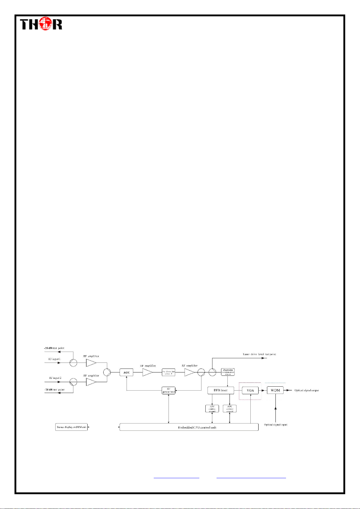
3. Block Diagram
Note: The optical attenuator in the red dashed box and the wavelength division multiplexer in the
blue dashed box are optional.

F-RF-1550-Tx
Tel: (800) 521-8467 Email: sales@thorfiber.com http://www.thorbroadcast.com
4. Technical Parameters
Item
Unit
Parameter
Optical part
Optical wavelength
nm
ITU wavelength
Laser type
Butterfly-typed DFB laser
Optical modulation mode
Direct optical intensity modulation
Optical connector type
FC/APC or SC/APC
Output optical power
mW
10
The insertion loss of the VOA and CWDM is
excluded.
External optical signal input
dBm
-5~10
RF Characteristics
Frequency range
MHz
47~870/1003/1218
RF input level
dBu
V
77± 5
Flatness in band
dB
± 0.75
Input return loss
dB
≥ 16
RF AGC control range
dB
±5
RF MGC adjustable range
dB
0~20
RF input isolation
dB
≥
50
Isolation between two RF inputs
RF input test port
dB
-20±1
Laser drive level test port
dB
-20±1
Electronically controlled
optical attenuator tolerance
dB
≤1: ATT 0-15dB
≤3: ATT 16-20dB
CNR
dB
≥
48
550MHZ 59CH analog signal 77dBuV/CH
550-870MHZ 40CH digital signal 67dBuV/CH
25 Km, -1dBm input
C/CSO
dB
≥
58
C/CTB
dB
≥
63
CNR
dB
≥
46
550MHZ 59CH analog signal 77dBuV/CH
550-870MHZ 40CH digital signal 67dBuV/CH
50Km, -1dBm input
C/CSO
dB
≥
55
C/CTB
dB
≥
63
MER
dB
≥
40
25 Km, -1dBm input, 96CH digital 77dBuV/CH
≥
39
50 Km, -1dBm input, 96CH digital 77dBuV/CH
Others
Maximum power
consumption
W
≤10
Operating temperature
℃
-5 ~+ 55
Storage temperature
℃
-30 ~+ 70
Weight
Kg
5.5

F-RF-1550-Tx
Tel: (800) 521-8467 Email: sales@thorfiber.com http://www.thorbroadcast.com
OUT:10
Unit:dBm
Laser output optical power
Optical power after attenuation (without WDM, no this menu)
External optical signal power (without WDM, no this menu)
Laser bias current
Internal temperature of the laser
Laser cooling current
Transmission channel numbers
Laser drive level
RF control mode
AGC offset (in AGC mode)
MGC attenuation (in MGC mode)
+5V monitoring voltage
-5V monitoring voltage
+24V monitoring voltage
Equipment wavelength
Serial number
Current internal temperature
Equipment IP address
Equipment subnet mask
Equipment gateway
Equipment MAC address
Equipment software version number
RF:30.5
Unit:dBu
V
Laser Output xx dBm
Voa Input xx dBm
Master Input xx dBm
Laser Bias xx mA
Laser Temp xx ℃
Tec current xx A
RF Chan No xx
Laser RF xx dBuV
RF Ctrl Mode AGC
AGC Ref x dB
MGC ATT x dB
Wave Length 1550
+5V Read x v
-5V Read x v
+24V Read x v
S/N
BOX Temp xx ℃
IP Address
Mask
GTW
Mac
SoftWare Ver
5. Operation instructions of the display menu
▲▼key: The cursor can be moved left or right or up and down, and the selected module or menu is
highlighted.
Enter key: Press Enter to enter the next submenu or set the parameters in the submenu. Press Enter to
confirm.
ESC key: Exit or return to the previous menu.
The menu displayed after power on: Press Enter to enter the first level submenu:
Disp Parameters, the second level submenu:
1.Disp Parameters
2.Set Parameters
3.Alarm Status
Parameter display menu
Parameter setting menu
Alarm status
Laser drive
level
Output optical
power

F-RF-1550-Tx
Tel: (800) 521-8467 Email: sales@thorfiber.com http://www.thorbroadcast.com
Optical power unit: dBm, mW optional
Buzzer alarm: ON, OFF optional
RF control mode: AGC, MGC optional
MGC attenuation: 0-20 optional
AGC offset: ±3dB optional
Set the optical power attenuation mode: AUTO or Manu optional
Without WDM, no
this menu
Set the optical power attenuation value: 0~15dB optional
Set the difference between the main optical power and the inserted optical
power
Set transmission distance: 0~50KM optional, 1KM stepping.
Set the channel number: 0-100 optional
Set the equipment IP address
Set the subnet mask
Set the gateway
Reset to the default
SetLaserOutputUnit dBm
Set BuzzerAlarm ON
SetRF ControlMode AGC
Set MGC ATT XX dB
Set AGC Ref XX dB
Set OPT ATT Mode AUTO
Set OPT ATT XX dB
Set OPT Delta XX dB
Set FiberC Length xxKM
SetChannel Number XX
Set IP Addr
Set Subnet Mask
Set GateWay
Restore Factory Config
Laser level alarm: The default normal range is 80~110dBuV, which can be set through the network
management.
Laser temperature alarm: The default normal range is 25±10°C, which can be set through the network
management.
Laser bias current alarm: The default normal range is 20~90mA, which can be set through the network
management.
Laser cooling current: The default normal range is -1.5~1.5A, which can be set through the network
management.
Output optical power alarm: The default normal range is 2 to 25 mW, which can be set through the network
management
+5V alarm: The default normal range is 5±1V, which can be set through the network management.
-5V alarm: The default normal range is -5±1V, which can be set through the network management.
+24V alarm: The default normal range is 24±2V, which can be set through the network management.
Set Parameters, the second level submenu:
Alarm Status, the second level submenu:
Laser RF
Laser Temp
Laser Bias
Laser TEC
Laser Output
+5V Alarm
-5V Alarm
+24V Alarm

F-RF-1550-Tx
Tel: (800) 521-8467 Email: sales@thorfiber.com http://www.thorbroadcast.com
6. Structure Description
Front panel
1
Power indicator
2
Device running indicator: This indicator will flash by 1Hz frequency after the device start running normally.
3
Laser working status indicator:
Steady green light: The laser is operating normally.
Steady red light: The laser is not turned on.
Blinking red light: The device has a parameter alarm. You can view the alarm in the Alarm Status, the second
level submenu.
4
Laser drive level indicator:
Steady green light: Drive level is normal.
Blinking red light: Drive level alarm. You can view the alarm in the Alarm Status, the second level submenu.
5
160×32 dot-matrix LCD screen: used to display all the parameters of the machine.
6
Display the exit or cancel key of the setup menu.
7
Display the up or increase key of the setup menu.
8
Display the down or decrease key of the setup menu.
9
Display the enter key of the setup menu.
10
Laser switch:
ON: The laser is on.
OFF: The laser is off.
Keep the laser off before the device is powered on, and turn on the laser after the self-inspection is
completed when power on.
11
Laser drive level test port: -20dB
Rear panel
1
Fan
7
Optical signal output
2
Ground stud, ensure good grounding before power on
8
Optical signal input: without WDM, no this port
3
RF input 1
9
RS232 interface
4
RF input 2
10
LAN interface
5
RF input 1 test port -20dB
11
Power module 1, hot swappable
6
RF input 2 test port -20dB
12
Power module 2, hot swappable

F-RF-1550-Tx
Tel: (800) 521-8467 Email: sales@thorfiber.com http://www.thorbroadcast.com
8. Attention
Ensure the package is not defaced. If you think the equipment has been damaged, please don't electrify
yourself. Check all contents carefully
Before the equipment is powered on, make sure the housing and the power socket is reliably
grounded. The grounding resistance should be <4Ω, so as to effectively protect against surges and
static electricity.
The optical transmitter is a professional device and its installation and debugging must be operated
on by a special technician. Read this manual carefully before operating to avoid damage to
equipment caused by fault operation or accident harm to the operator.
While the optical transmitter is working, there is an invisible laser beam coming from the
optical output adapter on the rear panel.
To avoid permanent harm to the body and eye, the optical output should not be aimed
at any human or looked at with the naked eye!
When the fiber connector is not in use, it should be housed with a dust jacket to avoid dust pollution
and to keep the fiber tip clean.
9. Packing List
F-RF-1550-Tx 1PC
User's Manual 1PC
Power Cord 1PC
For Further Tech Support
1-800-521-Thor(8467)
Table of contents
Other Thor Broadcast Transmitter manuals
Popular Transmitter manuals by other brands

FlowLine
FlowLine EchoSonic II LU23 Series manual

Dedicating Creation Technology
Dedicating Creation Technology CZH-05B instruction manual

Ascon tecnologic
Ascon tecnologic ATT1 Engineering manual

Spektrum
Spektrum NX20 instruction manual

Questtel
Questtel 1B-SDI-W-TX user manual

Emco
Emco TSDM-2400 user guide

FISCHER
FISCHER DE45 R/S Series operating manual

DMP Electronics
DMP Electronics 1144INT Series installation guide

Michell Instruments
Michell Instruments Easidew PRO I.S. user manual

Peiying
Peiying URZ0479 owner's manual

Endress+Hauser
Endress+Hauser RMA 422 operating instructions

Load Range Systems
Load Range Systems T74USB user manual