THORLABS EDU-3D1 User manual

EDU-3D1
EDU-3D1/M
Polarization and
3D Cinema Technology Kit
User Guide

Polarization and 3D Cinema Technology Kit
Table of Contents
Chapter 1Warning Symbol Definitions ....................................................... 1
Chapter 2Safety ............................................................................................ 2
Chapter 3Product Description .................................................................... 3
Chapter 4Setup ............................................................................................. 4
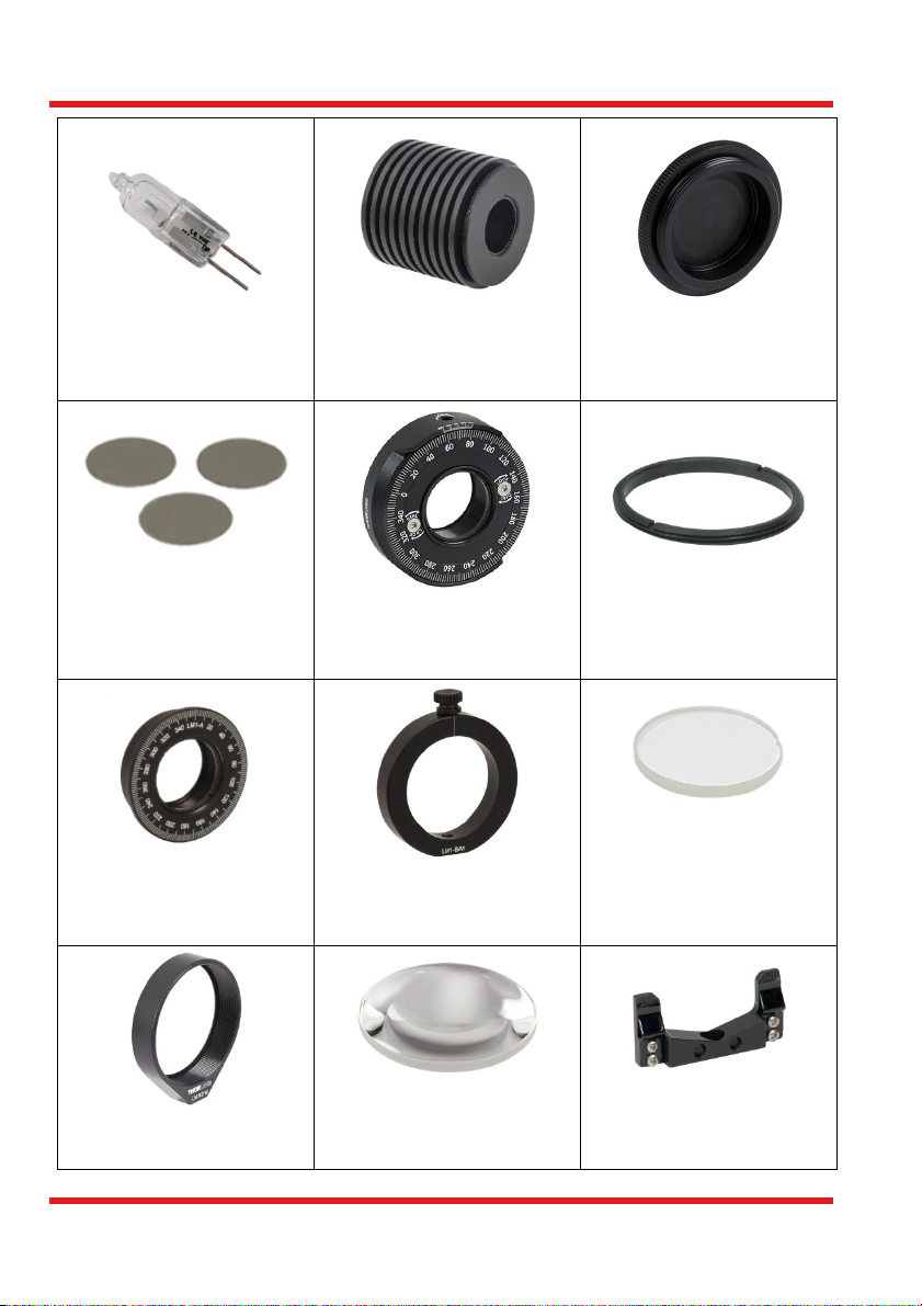
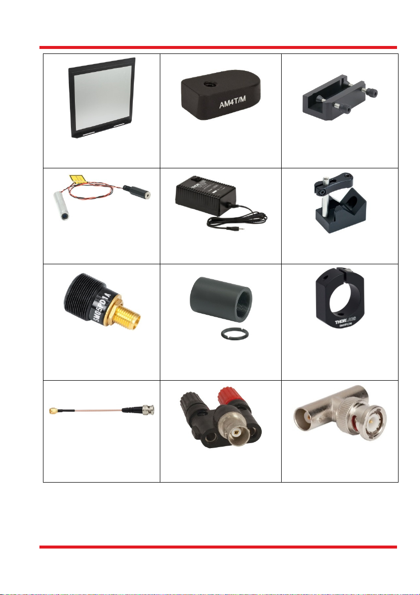
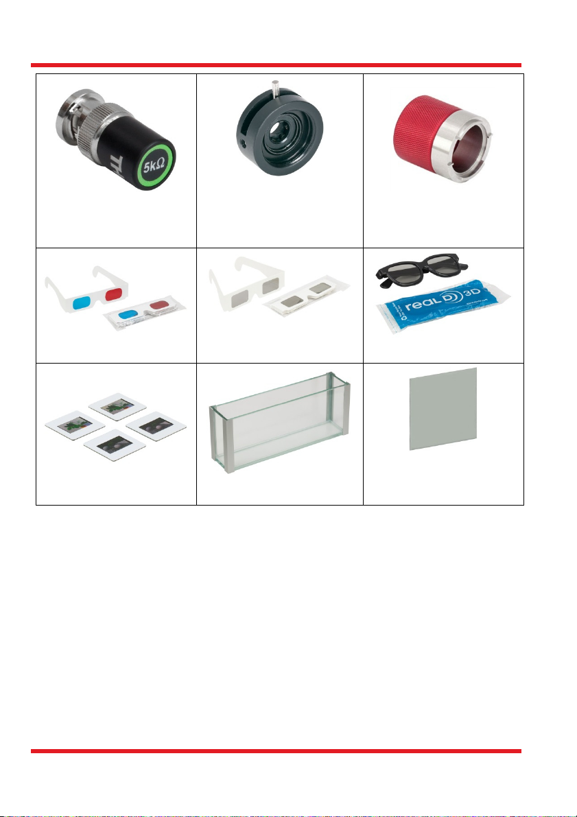
4.1.ComponentsandPartsList.....................................................4
Chapter 5Underlying Theoretical Principles ............................................. 9
5.1.Polarization............................................................................9
5.1.1.Linear Polarization .................................................................................... 9
5.1.2.Circular Polarization ................................................................................ 10
5.1.3.Polarizer and Malus’ Law ........................................................................ 10
5.1.4.λ/4 Plates ................................................................................................ 11
5.1.5.Behavior of a λ/4 Plate and Polarizer in Series ....................................... 12
5.1.6.Optical Activity ......................................................................................... 14
5.1.7.Stress-Induced Birefringence .................................................................. 16
5.1.8.Representation with Jones Matrices ....................................................... 16
5.2.Stereoscopy..........................................................................17
5.2.1.The Basic Idea ........................................................................................ 17
5.2.2.Anaglyph Images .................................................................................... 17
5.2.3.Stereoscopy with Linear Polarizers ......................................................... 19
5.2.4.RealD Method ......................................................................................... 20
5.2.5.Other Methods ........................................................................................ 22
5.3.CreatingYourOwn3DImages..............................................22
Chapter 6Setup and Adjustment ............................................................... 26
6.1.AssemblyoftheComponents................................................26
6.2.3DSetupandAdjustment.....................................................31
6.2.1.Correct Adjustment of the Linear Filter ................................................... 31
6.2.2.Setup the Slides, Lamps, and Lenses ..................................................... 32
6.2.3.Positioning the Polarizers and Adjusting the Films and Plates ............... 34
6.2.4.Final Adjustment ..................................................................................... 36
6.3.3DImages............................................................................37
Chapter 7Exercises and Examples ........................................................... 38
7.1.PolarizationExperiments......................................................38
7.1.1.Preliminary Experiments ......................................................................... 38
7.1.2.Malus’ Law .............................................................................................. 38
7.1.3.Measuring the Polarization State of the Laser ........................................ 39
7.1.4.Determining the Orientation of the λ/4 Plate ........................................... 40

Polarization and 3D Cinema Technology Kit
7.1.5.Behavior of λ/4 Plate for Green Light ...................................................... 41
7.1.6.Saccharimetry ......................................................................................... 42
7.1.7.Stress-Induced Birefringence .................................................................. 44
7.2.3DMethodwithRed‐CyanGlasses.......................................45
7.3.3DProjectionwithLinearFilters...........................................46
7.4.3DProjectionwiththeRealDMethod...................................47
7.4.1.Preliminary Tests with the Glasses ......................................................... 47
7.4.2.3D Projection ........................................................................................... 48
Chapter 8Exercise Overview ..................................................................... 49
Chapter 9Troubleshooting and Comments ............................................. 50
Chapter 10Regulatory .................................................................................. 51
10.1.WasteTreatmentisYourOwnResponsibility........................51
10.2.EcologicalBackground..........................................................51
Chapter 11Thorlabs Worldwide Contacts .................................................. 52

Polarization and 3D Cinema Technology Kit Chapter 1: Warning Symbol Definitions
Page 1 Rev H, December 10, 2018
Chapter 1 Warning Symbol Definitions
Below is a list of warning symbols you may encounter in this manual or on your device.
Symbol Description
Direct Current
Alternating Current
Both Direct and Alternating Current
Earth Ground Terminal
Protective Conductor Terminal
Frame or Chassis Terminal
Equipotentiality
On (Supply)
Off (Supply)
In Position of a Bi-Stable Push Control
Out Position of a Bi-Stable Push Control
Caution: Risk of Electric Shock
Caution: Hot Surface
Caution: Risk of Danger
Warning: Laser Radiation

Polarization and 3D Cinema Technology Kit Chapter 2: Safety
MTN004316-D02 Page 2
Chapter 2 Safety
CAUTION
IMPORTANT: The polarizer films are covered on each side with a clear, protective
film. We strongly recommend wearing gloves when assembling the polarizers and
quarter-wave plates so that the films and windows are not touched with bare fingers.
Avoid exposure of the film polarizers to UV light, to high temperatures, and to
chemicals such as acetone.
WARNING
The laser module is a Class 2 laser, which does not require any protective eyewear.
However, to avoid injury, do not look directly into the laser beam.
CAUTION: HOT SURFACE
After the QTH10 lamp warms up, the heat sink will reach a temperature of 50 °C if the
standard bulb is used. If you are using the 16 W bulb that is provided in this kit (with
the additional heat sink properly installed), the housing temperature can reach up to
65 °C. Be careful not to touch the lamp housing during operation.
!
!

Polarization and 3D Cinema Technology Kit Chapter 3: Product Description
Page 3 Rev H, December 10, 2018
Chapter 3 Product Description
Polarization is one of the most multifaceted properties of light. Countless applications in
science and technology are based on it, some of which are simulated in this experiment
kit.
First, the basic properties of polarization are studied by observing how polarized light
behaves when it is incident on a polarizer (Malus’ Law). As a next step, the state of
polarization of a laser is measured with a polarizer and a photodetector.
The λ/4 (quarter-wave) plate represents an essential element for applications with
polarized light. When correctly oriented, it delays parts of the wave in such a way that a
circularly polarized wave is produced from incident light with linear polarization. The
polarization state of the transmitted light is one of the properties that we examine
quantitatively in this kit.
Furthermore, technical applications are demonstrated. The components included in this
package can be used to set up a measuring apparatus with which you can examine the
concentration of sugar in a liquid. The sugar rotates the polarization of incident light
proportional to the distance traversed in the medium and to the glucose concentration.
This measurement of a sugary solution demonstrates how concentration measurements
are carried out for industrial applications.
Another technological application is materials testing using birefringence – here, a work
piece (e.g. a pair of plastic glasses) is held between crossed polarizers. Birefringence is
induced in places where mechanical stress occurs, and the polarization of light passing
through the piece is rotated dependent on the wavelength. If crossed polarizers are placed
on either side of the object, potential failure points will be visible as areas appearing in
different colors.
A large part of this experiment kit is devoted to an application which has now entered our
everyday lives: 3D cinema. Two images taken from a slightly different perspective are
projected so that each image enters only one eye. When correctly superimposed, the
impression of depth perception is created. Experimentally, several different processes can
now be used to ensure that each eye only takes in one image: the red-cyan method, the
3D projection method using linear polarization, and the now well-established RealD
method with circular polarization. This kit includes the appropriate glasses are for each of
these methods. As a special feature, a piece of real cinema screen, coated with vaporized-
silver to preserve the polarization of reflected light, is provided for the experiments using
the RealD and linear polarization methods.

Polarization and 3D Cinema Technology Kit Chapter 4: Setup
MTN004316-D02 Page 4
Chapter 4 Setup
4.1. Components and Parts List
In cases where the metric and imperial kits contain parts with different item numbers,
metric part numbers and measurements are indicated by parentheses unless otherwise
noted.
1 x MB1224 (MB3060/M)
Aluminum Breadboard,
12" x 24" (30 cm x 60 cm)
1 x RDF1
4 Rubber Breadboard Feet
8 x BA2(/M)
Mounting Base,
2" x 3" x 3/8"
(50 mm x 75 mm x 10 mm)
6 x BA1S(/M)
Mounting Base,
1" x 2.3" x 3/8"
(25 mm x 58 mm x 10 mm)
1 x BA1(/M)
Mounting Base,
1" x 3" x 3/8"
(25 mm x 75 mm x 10 mm)
14 x TR3 (TR75/M)
Ø1/2" (Ø12.7 mm)
Mounting Post,
3" (75 mm) Long
12 x PH3 (PH75/M)
Ø1/2" (Ø12.7 mm) Post
Holder, 3" (75 mm) Long
2 x UPH3 (UPH75/M)
Ø1/2" (Ø12.7 mm) Post
Holder, 3" (75 mm) Long
2 x QTH10(/M)
Quartz Tungsten-Halogen
Lamp

Polarization and 3D Cinema Technology Kit Chapter 4: Setup
Page 5 Rev H, December 10, 2018
2 x Halogen Bulbs,
16 W, 230 lumen
2 x HSLT2
Passive-Heat-Sink
SM1 Lens Tube with
External SM2 Threads
2 x SM1CP2
Externally SM1-Threaded
End Cap
1 x LPVISE2X2
Linear Polarizer
(Laser Cut into 3
Ø1" Circles)
2 x RSP1D(/M)
Ø1" Rotating Polarizer
Mounts
2 x SM1RR
SM1-Threaded
Retaining Ring
2 x LM1-A
Nested Ø1" Inner
Lens Carriage
2 x LM1-B(/M)
Nested Ø1" Lens Mount
Outer Ring
2 x Ø1" Quarter-Wave
Plate
(foil with N-BK7 windows)
2 x LMR2(/M)
Lens Mount for Ø2" Optics
2 x LB1630
N-BK7 Bi-Convex Lens, Ø2",
f = 100.0 mm, Uncoated
2 x FH2
Filter Holder for
2" Square Filters

Polarization and 3D Cinema Technology Kit Chapter 4: Setup
MTN004316-D02 Page 6
1 x Cinema Screen
(Mounted on TPS5)
2 x AM4T(/M)
4° Angle Block
1 x FP02
Wide Plate Holder
1 x CPS532-C2
532 nm Laser Diode
Module, Class 2
1 x LDS5(-EC)
5 VDC Laser Power Supply
1 x VC1(/M)
Small V-Clamp
1 x SM05PD1A
Silicon Photodiode,
350 - 1100 nm,
Cathode Grounded
1 x SM05M10
1″ Long SM05 Lens Tube
1 x SM05RC(/M)
Ø1/2″ Slim Slip Ring for
SM05 Lens Tubes,
8-32 (M4) Tapped Hole
1 x CA2812
12″ Long SMA Coaxial
Cable, SMA Male
to BNC Male
1 x T1452
BNC Female to Binding Post
1 x T3285
BNC Adapter – T Adapter
(F-M-F)

Polarization and 3D Cinema Technology Kit Chapter 4: Setup
Page 7 Rev H, December 10, 2018
1 x FT502
5 kΩ Fixed Stub-Style
BNC Terminator
1 x SM05D5
Lever-Actuated Iris
Diaphragm
(Ø0.7 mm - Ø5 mm)
1 x SPW606
SM1 Spanner Wrench,
Length = 1"
5 x Red-Cyan Glasses
4 x Linear Polarizer
3D Glasses
4 x RealD™ Glasses
2 x Pairs of Slides
1 x Glass Basin
1 x LPVISE2X2
2" x 2" Linear Polarizer
Sheet

Polarization and 3D Cinema Technology Kit Chapter 4: Setup
MTN004316-D02 Page 8
Imperial Kit Screws, Ball Driver, and Hex Keys
Type Quantity Type Quantity
1/4"-20 x 1/2" Cap Screw 25 1/4" Nut 4
1/4"-20 x 5/8" Cap Screw 25 1/4" Washer (W25S050) 100
1/4"-20 x 3/4" Cap Screw 4
1 x BD-3/16L
Balldriver for 1/4″-20 Screws
8-32 x 1/2" Cap Screw 4
1/4" Counterbore Adapter
Ring for 8-32 Screws 10
Hex Keys: 5/64", 7/64” and 9/64"
Metric Kit Screws, Ball Driver, and Hex Keys
Type Quantity Type Quantity
M6 x 12 mm Cap Screw 25 M6 Nut 4
M6 x 16 mm Cap Screw 25 M6 Washer (W25S050) 100
M6 x 20 mm Cap Screw 4
1 x BD-5ML
Balldriver for M6 Screws
M4 x 12 mm Cap Screw 4
M6 Counterbore Adapter
Ring for M4 Screws 10
Hex Keys: 3 mm, 2.5 mm and 2 mm

Polarization and 3D Cinema Technology Kit Chapter 5: Underlying Theoretical Principles
Page 9 Rev H, December 10, 2018
Chapter 5 Underlying Theoretical Principles
5.1. Polarization
Electromagnetic waves are transverse waves, which means that they oscillate
perpendicular to their direction of propagation. The direction of this oscillation, more
specifically the direction of the electric field, is referred to as direction of polarization. If the
field oscillates in a disorganized fashion, then it is called unpolarized light.
For polarization, we distinguish three possible cases: if the wave always oscillates only in
one direction, then we speak of linear polarization. If the vector of the electric field draws
a circular corkscrew around the direction of propagation, then we call it circular
polarization. All other instances of polarized light are then elliptically polarized, which
means the field vector describes an ellipse around the direction of propagation. In the
following section, the special cases of linear and circular polarization will be examined
more closely. We will use complex notation.
5.1.1. Linear Polarization
Let us start from a plane wave propagating in the z direction:
Incident:
(1)
Now, when the vector
E
0
always points in the same direction, we can write the equation
for the electric field as :
(2)
The light field is linearly polarized. Both components of the wave are in phase:
,
(3)
Figure 1 shows the real part of the electric field at a fixed time.
Figure 1 Snapshot of the electrical field vector in linearly polarized light.
E
0
E
0
y
Re(E) = E
0
cos(
-wt +kz
)
E
0
x
xx
y
y
z
Ө

Polarization and 3D Cinema Technology Kit Chapter 5: Underlying Theoretical Principles
MTN004316-D02 Page 10
5.1.2. Circular Polarization
In the case of circularly polarized light, and are the same size, but the and
components of the field are shifted with respect to each other by a quarter wavelength, or
a phase of /2.1
,
(4)
As shown in Figure 2, the real part of the electric field describes a circle in the plane,
and therefore a corkscrew along the direction. If you look in the direction of
propagation, then the vector rotates clockwise in the case of in Equation (4). This
polarization state is defined as left-circular or . Correspondingly, a right-circularly
polarized wave then rotates counterclockwise (as viewed looking in the direction of
propagation).2
Figure 2 Snapshot of the electric field vector in left-circularly polarized light.
5.1.3. Polarizer and Malus’ Law
Most polarizing filter sheets consist of stretched films in which the long-chain molecules
align end to end due to the stretching. Mobile charge carriers, which absorb the parallel
components of the electric field, are situated along these chains. The electric field
oscillation parallel to the molecules in the stretched chain is absorbed and the electric field
oscillation perpendicular to the chains is transmitted.
Polarizers thus have an orientation in which they effectively absorb all radiation and a
direction in which they transmit almost all the radiation. It should be noted that absorption
and transmission are never perfect – the degree depends on the wavelength and the
manufacturing cost of the polarizer.
1 It should be borne in mind: if you shift a component by /2, then you multiply with the phase factor
⁄cos
sin
.
2 Be careful with the definition of left and right circular; depending on the source, you either ‘look’
along the direction of propagation or you look towards the oncoming wave.
E
x
x
y
y
z

Polarization and 3D Cinema Technology Kit Chapter 5: Underlying Theoretical Principles
Page 11 Rev H, December 10, 2018
How then is a linearly polarized wave transmitted when it strikes a polarizer at an angle θ?
Figure 3 Distribution of the electric field of a linearly polarized wave on a polarizer.
As shown in Figure 3, we decompose the vector of the incident field into its components
parallel and perpendicular to the transmission direction of the polarizer. The proportion
that is transmitted is
||cos
θ
(5)
Since the intensity is measured as the absolute square of the field, the following intensity
distribution is obtained behind the polarizer
||||coscos
(6)
whereas the intensity of the light is before its transmission through the polarizer is
represented by . Equation (6) is known as Malus’ Law.
5.1.4. λ/4 Plates
Optical wave plates, or retarders, are made of a birefringent material that produces a
phase difference between the fast and the slow axis of the wave plate. The birefringent
properties of the material give the two axes a different refractive index. This in turn results
in a different propagation velocity for these two orthogonal axes: If the incident light is
polarized parallel to the slow axis, it experiences a high refractive index; in other words, it
propagates slowly. In contrast, light that oscillates parallel to the fast axis experiences a
smaller refractive index, causing it to propagate faster in comparison.
The resulting phase difference, Δ, between two waves that are each polarized parallel to
one of the two axes depends on the selected material, the thickness of the retarder plate,
and the wavelength of the incident light. It is calculated as
Δ 2
(7)
whereas and are the refractive indices and d is the thickness of the plate.
=Transmission Axis
Transmission Axis
E
0
E
0
y
E
0
x
xx
y
y
z
Ө

Polarization and 3D Cinema Technology Kit Chapter 5: Underlying Theoretical Principles
MTN004316-D02 Page 12
In a λ/4 (quarter-wave) plate (or λ/4 film as in this kit), the parameters are now chosen in
such a way that the retardation of the one axis with respect to the other is exactly one-
quarter wavelength (λ/4), corresponding to a phase difference of π/2.
This yields the following property: if linearly polarized light strikes a λ/4 plate with the fast
axis angled at 45° with respect to the light’s direction of polarization (the direction of
polarization is therefore exactly between the slow and fast axis), then the transmitted light
is circularly polarized.3 The mathematical description is discussed in general terms in the
next section.
At this point another important aspect still needs to be emphasized: As can be seen from
Equation (7), the effect of the λ/4 plate is strongly dependent on wavelength. This means,
in particular, that a λ/4 plate always only functions optimally for one wavelength. For all
other wavelengths, it will not produce a circular polarization, but ‘only’ elliptical
polarization4.
5.1.5. Behavior of a λ/4 Plate and Polarizer in Series
In the experimental section, we will examine the system shown in Figure 4, because it
provides an indication of the orientation and mode of action of the λ/4 plate.
Figure 4 Linearly polarized light is incident on a λ/4 plate and a polarizer.
In this section, we will determine the expected intensity at the detector as a function of the
angle of the fast axis of the wave plate, , and the angle of the transmission axis of the
polarizer, Ψ. We start with an incident plane wave that is polarized in the y direction. With
the unit vector in the y direction,
, we can describe the plane wave mathematically with
the following equation:
Incident:
E
i
n
k
z
ω
t
(8)
3 Conversely, linearly polarized light can again be generated from circularly polarized light by
passing it through another quarter-wave plate.
4 There exist special cases where a retarder works for a broader frequency range. These are called
achromatic retarders and are based on a carefully selected combination of and , which
normally are also frequency dependent quantities.
Polarization State
of the Laser
Laser λ/4-Plate Polarizer
Transmission Axis
Detector
Fast
Axis
Slow
Axis
ψ
θ

Polarization and 3D Cinema Technology Kit Chapter 5: Underlying Theoretical Principles
Page 13 Rev H, December 10, 2018
This incident linearly polarized plane wave now strikes the λ/4 plate. To describe the
transmission accurately, we divide the incident wave into two components that are parallel
to the fast axis,
, or parallel to the slow axis,
∥.
⋅
⋅
∥
∥
sin
cos
∥
(9)
To visualize this relationship, the following sketch might help:
Figure 5 Illustration of the Unit Vectors
These two parts are now transmitted through the λ/4 plate. Since the two axes of the wave
plate have different refractive indices, light polarized parallel to the slow axis will travel
through the plate at a different speed than light polarized along the fast axis. λ/4 plates are
designed so that the light polarized parallel to the slow axis will have traveled an additional
quarter wavelength when it exits the plate compared to the light polarized parallel to the
fast axis. This means that light polarized parallel to the fast axis undergoes a phase shift
of after it travels through the wave plate and the light polarized parallel to the slow axis
experiences phase shift of π/2 (a relative phase shift equivalent to λ/4, or 90 °) – it is
exactly this phase difference that defines this axis as the ‘slow’ axis. The field E behind
the λ/4 plate is therefore
sin
cos
∥/ (10)
As a last step, this light now strikes the polarizer, which is rotated by the angle Ψ relative
to the y axis. Of the two parts in Equation (10) in each case again only the part in direction
is transmitted, in other words the projection to
. The electric field at the detector
is then5
sin
⋅
cos
∥⋅
/
(11)
sincos90°Ψ
coscosΨ
sinsinΨcoscosΨ
5 Here it is important to recall ∙, coscos, cos90°sin,
and / cos 2
⁄sin/2.
Ө
ӨӨ
yy
ê
‖
êê
ê
‖
ê
|
ê
|
Ψ
Polarizer
Transmission
Axis

Polarization and 3D Cinema Technology Kit Chapter 5: Underlying Theoretical Principles
MTN004316-D02 Page 14
The intensity at the detector is calculated as the absolute value of the square of the electric
field6 and thus
||
sinsincoscos
(12)
If the second polarizer is placed with the transmission axis perpendicular to the first,
rotating the wave plate through 180° will yield the following intensity:
Figure 6 Representation of the intensity after Equation (12) as a function of the angle of
rotation of the λ/4 plate in between crossed polarizers (transmission axis at °) and
.
As described above, the 45° orientation of the wave plate fast axis with respect to the
linearly polarized incident light produces a circular output polarization. As you rotate the
wave plate, the output polarization state will change from circular (when θ = 45°) to linear
oriented perpendicular to the transmission axis of the second polarizer (when θ = 0°). The
intensity measured behind the last polarizer will reach a maximum when the fast axis of
the λ/4 plate is oriented at 45° with respect to the transmission axes of the polarizers; i.e.
when the light incident on the last polarizer is circularly polarized.
5.1.6. Optical Activity
As we show experimentally in this kit, a solution of sugar and water rotates the polarization
of the transmitted light. This can be understood if you know that sugar molecules have a
sense of rotation in their structure. This direction of rotation causes the left and right
circularly polarized light to be transmitted differently. It is obvious that light with a
polarization that has the same direction of rotation (chirality) as the molecule exhibits
different transmission characteristics (that is, a different refractive index) than the light that
has a polarization state that oscillates in the other direction of rotation.
6 As a reminder, it is important to point to the complex calculation rules 1 for all and
||⋅.

Polarization and 3D Cinema Technology Kit Chapter 5: Underlying Theoretical Principles
Page 15 Rev H, December 10, 2018
First, we will briefly consider what happens when linearly polarized light is incident on such
a material. We first assume that the light is linearly polarized in the x direction and
propagates in the z direction. In other words:
Incident: ,
(13)
Like any linearly polarized field, this field can now be decomposed into a right- and a left-
circularly polarized part. We write the circular fields in complex notation. The result is this
(see Chapter 5.1.2):
0,
0
0 1
2
01
2
0 (14)
As described above, the left and right-circular parts of the field experience a different
refractive index and , since they oscillate either with or against the direction of rotation
of the molecule. After the field propagates a distance, , in the medium, it can be described
as follows:
,1
2
0 1
2
0
(15)
1
21
0/
1
0/
cos
sin
0
Whereas we have defined /2 and /2 here. Thus, the
polarization is rotated by an angle that depends on which distance, , the light passes
through the medium.
It can be seen that the angle of rotation is proportional to the length . Furthermore, the
angle of rotation is also proportional to the concentration c, because this determines the
difference in the refractive indices and . So the angle of rotation follows the following
formula:
⋅⋅
(16)
The proportionality constant, , is a temperature- and wavelength-dependent quantity.
The effect of this rotation of polarization is often used in the industry to determine the sugar
concentration of various solutions. Therefore, devices used for this purpose are often
called polarimeters or saccharimeters.

Polarization and 3D Cinema Technology Kit Chapter 5: Underlying Theoretical Principles
MTN004316-D02 Page 16
An interesting aspect is that different sugars will affect the polarization of the transmitted
light differently – commercially available sugar and sorbose rotate the polarization in
different directions!
5.1.7. Stress-Induced Birefringence
Birefringence is a property of media that transmit light differently depending on its
polarization state and direction of propagation. These media are referred to as anisotropic,
meaning that they have different refractive indices for different propagation directions and
polarization states. A typical example is calcite.
Interestingly, this effect does not only occur in anisotropic materials. Birefringence can also
occur in some media composed of isotropic materials when they are stressed; that is,
placed under the strain of stretching, pressure, shearing or any other elastic deformation.
For example, if a piece of plastic is exposed to strong pressure at one point, the result is
a change in the tension in the material that varies with respect to the distance from that
point. This creates regions with different refractive indices and varying degrees of
polarization rotation. The magnitude of both of these properties is in turn dependent on the
wavelength of the light transmitted through the material. If you place the piece of plastic in
question between two crossed polarizers (polarizers with perpendicular transmission
axes), you will see different colors in regions of the material experiencing different amounts
of tension. This principle is used to perform contactless materials analysis.
5.1.8. Representation with Jones Matrices
Until now a plane wave was always used as point of departure for the mathematical
description of the polarization state and the effects of optical components on the
propagation of the polarized light. The Jones formalism allows an even shorter notation by
representing each optical element as a matrix. Multiplying the amplitude vector by the
matrix then gives us the amplitudes of the field behind the optical element.
As an example, we start with a linearly polarized field,
(17)
which allows the Jones vector J to be defined right away. A polarizer with the transmission
axis aligned in the direction is represented by the matrix 10
00
. Using this matrix, we
can describe the transmission of the field through the polarizer as follows:
10
00
⋅
0
(18)
The transmitted field is therefore polarized only in the direction, as it should be. From the
calculations shown above you can quite easily read the different vectors that describe the
polarization states and (slightly more difficult) the matrices that represent the optical
components.

Polarization and 3D Cinema Technology Kit Chapter 5: Underlying Theoretical Principles
Page 17 Rev H, December 10, 2018
The matrices for polarization states are, for example:
Linearly polarized in y: 0
1 Left-circular: 1
√
21
i
Linearly polarized at 45°: 1
√
21
1 Right-circular: 1
√
21
i
The matrices for the optical components are, for example:
Polarizer with transmission
axis in y direction
(linearly polarized light): 00
01
λ/4 plate with fast
axis in x: 1
√
21i 0
0 1i
Polarizer with transmission
axis in a 45° position
(for linearly polarized light): 1
211
11
5.2. Stereoscopy
5.2.1. The Basic Idea
The term ‘stereoscopy’ refers to the effect in which the correct superposition of two images
can lead to a sense of depth.
A person’s ability to perceive depth is based on the fact that each eye takes in one image
of the same environment, but from a slightly different perspective. From these different
perspectives, the brain calculates the three-dimensional position of the object relative to
the viewer.
The basic principle of any 3D display (movies or images) is to direct two images captured
from different perspectives into the eyes of the viewer, with only one image entering each
eye. Analogous to normal vision, the brain then constructs an impression of depth from
the two different images. In the following sections we will discuss various methods for
achieving this condition to create 3D projection, i.e., only one image enters each eye and
consequently different information arrives at each eye.
5.2.2. Anaglyph Images
The rather simple anaglyph technology is based on the coloring of the two different images
and a viewer looking at the superposition of both images through color filters.
This manual suits for next models
1
Table of contents
Popular Educational Equipment manuals by other brands

CAE Healthcare
CAE Healthcare Replay Ultraportable Getting started guide

GeoSafari
GeoSafari Light Adventure EI-5283 quick start guide

Keysight Technologies
Keysight Technologies U3851A Getting started guide

Learning Resources
Learning Resources gloPane quick start guide

timio
timio TM03-03 user manual

ScienTECH
ScienTECH 2261 Product tutorial