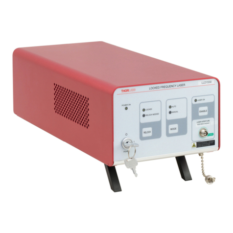
4-Channel Fiber Coupled Laser Source
18659-D02 Rev B, September 21, 2011 Page 5 www.thorlabs.com
Part 2. Description
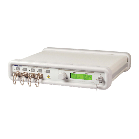
The Thorlabs 4-Channel Fiber Coupled Laser Sources provide easy coupling and simple control of laser
diode driven fiber optics. Each system is equipped with four fiber output light sources with wavelength
available from 406 to 1550 nm. The laser source is configured to accept a wide range of fiber pigtailed
laser diodes, and each system can be made with single mode fiber or PM fiber and any combination of 4
laser wavelengths. Below is a sample list of available wavelengths; please visit our website for a full list
of currently available options. Please contact Tech Support to configure your laser system.
Item # λ
Minimum
Power Laser Type Fiber
LPS-406-FC-LS 406 nm 3.0 mW Fabry-Perot S405
LPS-473-FC-LS 473 nm 4.0 mW Fabry-Perot S460
LPS-488-FC-LS 488 nm 4.5 mW Fabry-Perot S460
LPS-635-FC-LS 635 nm 2.5 mW Fabry-Perot SM600
LPS-658-FC-LS 658 nm 6.0 mW Fabry-Perot SM600
LPS-670-FC-LS 670 nm 1.5 mW Fabry-Perot SM600
LPS-785-FC-LS 785 nm 4.0 mW Fabry-Perot SM800-5.6-125
LPS-808-FC-LS 808 nm 4.5 mW Fabry-Perot SM800-5.6-125
LPS-850-FC-LS 850 nm 4.5 mW Fabry-Perot SM800-5.6-125
LPS-904-FC-LS 904 nm 4.5 mW Fabry-Perot SM800-5.6-125
LPS-980-FC-LS 980 nm 4.5 mW Fabry-Perot 980HP
LPS-1310-FC-LS 1310 nm 1.5 mW Fabry-Perot SMF28
LPS-1550-FC-LS 1550 nm 1.0 mW Fabry-Perot SMF28
LPS-1550DFB-FC-LS 1550 nm 1.5 mW DFB CF126-900
Each laser diode operates from an independent, high-precision, low-noise, constant-current source and
temperature control unit. An intuitive LCD interface allows the user to view and set the parameters for
each laser. The user can adjust the laser current and temperature control independently for each output.
The display indicates the channel number selected, the output wavelength of the source, the operating
power calculated from the laser diode monitor diode, and the actual temperature the laser is set to.
This device includes a microcontroller to fully control the laser’s optical power, temperature, and
monitor the system for fault conditions. The laser source includes a USB connection that allows remote
adjustment of power, temperature, and enabling. On the rear panel, analog inputs are available to
modulate the lasers with an external signal. This is added to the internal set points. To prevent damage,
the microcontroller will disable the output if the analog input plus the internal set point exceeds the laser
limits.
While most output sources fall within the class 3R laser rating, the system was fully designed to meet
3B laser class requirements. There is an interlock located on the rear panel that must be shorted in order
for any laser output to be enabled. This can easily be configured to be triggered by doors to disable the
Artisan Technology Group - Quality Instrumentation ... Guaranteed | (888) 88-SOURCE | www.artisantg.com
