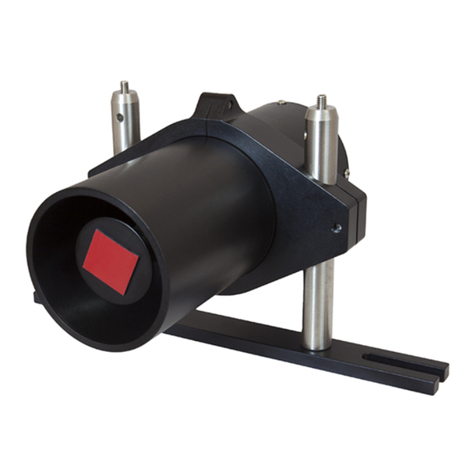
THORLABS LEDD1 User manual

microscopy instrumentation & accessories
T-CUBE LED DRIVER
Model Number LEDD1

THORLABS
About the Company
Thorlabs has been an active member of the Photonics community for over 15 years.
We strive to be the ultimate resource for the photonics community-a place to find the
products you need to enable your experiments, as well as the information you need to get
your application working.
Thorlabs designs, develops, and manufactures building blocks for the photonics industry
including equipment for opto-mechanics, motion control, nano-positioning, alignment,
optical components, laser diodes, tunable lasers and vibration isolation systems. In
addition to core photonics building blocks, we now provide system level solutions
including complete OCT and imaging systems.
Trademarks
THORLABS is a registered trademark of
Thorlabs Inc.
Product Warranty
Opto-Electronics, Control Electronics,
Optics, and Nano-Positioning Product
Lines.
Thorlabs offers a two year warranty on the
above mentioned product lines, provided
normal use and maintenance of the
products and when properly handled and
correctly installed.
Thorlabs shall repair or replace any
defective or nonconforming product as
detailed above. We ask that buyer contact
Thorlabs for a Return Material
Authorization number (RMA #) from our
Customer Service/Returns department in
order to most efficiently process the return
and/or repair.
Products returned for repair that are not
covered under warranty, a Thorlabs
standard repair charge shall be applicable
in addition to all shipping expenses. This
repair charge will be quoted to the
customer before the work is performed.
Revision History
Issue No. Date Summary
1 231106 Initial Issue
2 301107 Initial Issue

1
Contents
1 For Your Safety ......................................................................................... 3
Safety Information ..........................................................................................................3
Warnings Relating To The LEDD1 Driver .......................................................................3
General Precautions Relating To LED Safety ................................................................4
Declarations Of Conformity ............................................................................................4
For Customers in Europe .......................................................................................4
For Customers In The USA ....................................................................................4
Waste Electrical and Electronic Equipment (WEEE) Directive .......................................5
Compliance ............................................................................................................5
Waste treatment on your own responsibility ..........................................................6
Ecological background ...........................................................................................6
2 Overview and Setup ................................................................................... 7
Introduction .....................................................................................................................7
T-Cube Controller Hub ...................................................................................................8
3 Getting Started ........................................................................................... 9
Connect The Hardware ..................................................................................................9
Mechanical Installation .................................................................................................10
Environmental Conditions ....................................................................................10
Mounting Options .................................................................................................10
Removing the Baseplate ......................................................................................11
Electrical Installation .....................................................................................................12
Connecting an LED ..............................................................................................12
Using The TCH001 Controller Hub ......................................................................13
Supply Voltage and Current Requirements .........................................................13
Connecting To A Standalone Power Supply ........................................................14
Continued...

2
4 Operation ................................................................................................. 15
Introduction .................................................................................................................. 15
Front Panel Controls and Indicators ............................................................................ 15
Operation From The Front Panel ................................................................................. 16
Appendices
Rear Panel Connector Pinout Details ......................................................... 17
Rear Panel LED Connector .......................................................................................... 17
Preventive Maintenance .............................................................................. 18
Safety Testing .............................................................................................................. 18
Cleaning .......................................................................................................................18
Specifications and Associated Products ................................................... 19
Specifications ............................................................................................................... 19
Associated Products .................................................................................................... 20

3
Chapter 1
For Your Safety
1.1 Safety Information
For the continuing safety of the operators of this equipment, and the protection of the
equipment itself, the operator should take note of the Warnings, Cautions and Notes
throughout this handbook and, where visible.
The following safety symbols may be used throughout the handbook:
Warning. An instruction which draws attention to the risk of injury or death.
Caution. An instruction which draws attention to the risks of damage to the product,
process or surroundings.
Note. Clarification of an instruction or additional information.
1.2 Warnings Relating To The LEDD1 Driver
Warnings.
• The unit must be connected only to a DC supply of 15V, 1A regulated as detailed in
Section 3.3. Thorlabs offer a compact, multi-way power supply unit (TPS008), allowing
up to eight Driver T-Cubes to be powered from a single mains outlet. A single way wall
plug supply (OPS001) for powering a single Driver T-Cube is also available.
• Only personnel trained in the servicing and maintenance of this equipment should
remove its covers or attempt any repairs or adjustments.
• If this equipment is used in a manner not specified by the manufacturer, the protection
provided by the equipment may be impaired. Do not operate the instrument outside its
rated supply voltages or environmental range. In particular, excessive moisture may
impair safety.
• This unit is intended for operation in the temperature range 5° to 40°C, 20% to 80% RH.

4
Chapter 1 For Your Safety
1.3 General Precautions Relating To LED Safety
Warnings.
• Inappropriate use of any Thorlabs High Power LED product could result in permanent
eye damage.
• To prevent injury, these products must be used in accordance with the International
Standard "Photobiological Safety of Lamps & Lamp Systems" CEI IEC 62471
• When Thorlabs high power LED's are used in microscope applications as a replacement
for Mercury Vapor lamps, the same precautions should be taken as those applying to
Mercury Vapour lamps.
• When Thorlabs High Power LED's are used in other applications, they should be used in
accordance with CEI IEC 62471.
Cautions
• During normal operation, the casing temperature of Thorlabs High Power LED products
will rise by up to 25 C (45F) above ambient temperature.
• To prevent higher case temperatures, the products should be operated without hindrance
to air movement surrounding the convective cooling fins.
1.4 Declarations Of Conformity
1.4.1 For Customers in Europe
This equipment has been tested and found to comply with the EC Directive
89/336/EEC ‘EMC Directive’.
Compliance was demonstrated by conformance to the following specifications which
have been listed in the Official Journal of the European Communities:
EMC EN61326: 1997
1.4.2 For Customers In The USA
This equipment has been tested and found to comply with the limits for a Class A
digital device, pursuant to part 15 of the FCC rules. These limits are designed to
provide reasonable protection against harmful interference when the equipment is
operated in a commercial environment. This equipment generates, uses and can
radiate radio frequency energy and, if not installed and used in accordance with the
instruction manual, may cause harmful interference to radio communications.
Operation of this equipment in a residential area is likely to cause harmful interference
in which case the user will be required to correct the interference at his own expense.
Changes or modifications not expressly approved by Thorlabs Ltd. could void the
user’s authority to operate the equipment.
5
LEDD1 LED Driver T-Cube
1.5
Waste Electrical and Electronic Equipment
(WEEE)
Directive
1.5.1 Compliance
As required by the Waste Electrical and Electronic Equipment (WEEE) Directive of
the European Community and the corresponding national laws, Thorlabs offers all
end users in the EC the possibility to return "end of life" units without incurring
disposal charges.
This offer is valid for Thorlabs electrical and electronic equipment
• sold after August 13th 2005
• marked correspondingly with the crossed out "wheelie bin" logo (see Fig. 1)
• sold to a company or institute within the EC
• currently owned by a company or institute within the EC
• still complete, not disassembled and not contaminated
Fig. 1.1 Crossed out "wheelie bin" symbol
As the WEEE directive applies to self contained operational electrical and electronic
products, this "end of life" take back service does not refer to other Thorlabs products,
such as
• pure OEM products, that means assemblies to be built into a unit by the user (e. g. OEM
laser driver cards)
• components
• mechanics and optics
• left over parts of units disassembled by the user (PCB's, housings etc.).
If you wish to return a Thorlabs unit for waste recovery, please contact Thorlabs or
your nearest dealer for further information.

6
Chapter 1 For Your Safety
1.5.2 Waste treatment on your own responsibility
If you do not return an "end of life" unit to Thorlabs, you must hand it to a company
specialized in waste recovery. Do not dispose of the unit in a litter bin or at a public
waste disposal site.
1.5.3 Ecological background
It is well known that WEEE pollutes the environment by releasing toxic products
during decomposition. The aim of the European RoHS directive is to reduce the
content of toxic substances in electronic products in the future.
The intent of the WEEE directive is to enforce the recycling of WEEE. A controlled
recycling of end of life products will thereby avoid negative impacts on the
environment.

7
Chapter 2
Overview and Setup
2.1 Introduction
The T-Cube LED Driver (LEDD1) is a new very compact single channel controller for
easy control of LED intensity. It is designed for use with Thorlabs range of collimated
and mounted high power LED packages, and controls current flow to the LED by
means of a single turn control knob. LED power is controlled by one of 2 selectable
modes: continuous or an externally generated 0 to 5V signal. The continuous mode
is ideal for imaging with CCD cameras or photodiodes. When operating in the pulsed
mode, the user generated signals could be used to strobe the LED, or control average
power by way of pulse width modulation (up to 10 kHz rep rate).
For convenience the footprint of this unit has been kept to a minimum, measuring only
60mm x 60mm x 47mm (2.4" x 2.4" x 1.8") and with the facility to directly mount to the
optical table. The manual controls for this unit are conveniently located on the upper
surface. The Mode switch allows the ‘Continuous’ or ‘Pulsed’ operating modes to be
selected easily and the Brightness control is used to adjust the intensity of the
associated LED.
Fig. 2.1 LEDD1 T-Cube LED Driver with LEDC1 Collimator Assembly
For power, a compact multi-way power supply unit (TPS008) is available from
Thorlabs allowing up to 8 T-Cube Drivers to be powered from a single mains outlet.
This power supply unit is also designed to take up minimal space and can be mounted
to the optical table in close proximity to the driver units, connected via short power
leads. A single way wall plug supply (OPS001) is also available for powering a single
T-Cube Driver.
In the remainder of this handbook, installation and connection of the unit is described
in Chapter 3, and operation of the unit is described in Chapter 4.

8
Chapter 2 Overview and Setup
2.2 T-Cube Controller Hub
As a further level of convenience when using the new T-Cube Controllers Thorlabs
also offers the new T-Cube Controller Hub (TCH001). This product has been
designed specifically with multiple T-Cube operation in mind in order to simplify issues
such as cable management, power supply routing, multiple USB device
communications and different optical table mounting scenarios.
The T-Cube Controller Hub comprises a slim base-plate type carrier (375mm x 86mm
x 21.5mm, 14.75” x 3.4” x 0.85”) with electrical connections located on the upper
surface to accept up to six T-Cubes.
Note. The LEDD1 LED Driver is a manually operated unit with no USB functionality.
However if it is used on the TCH001, USB communications can be employed for any
other T-Cubes in the application.
Internally the Controller Hub contains a fully compliant USB 2.0 hub circuit to provide
communications for all six T-Cubes – a single USB connection to the Controller Hub
is all that is required for PC control. The Controller Hub also provides power
distribution for up to six T-Cubes, requiring only a single power connection (from a
separate supply unit TPS006 supplied by Thorlabs).

9
Chapter 3
Getting Started
3.1 Connect The Hardware
1) Perform the mechanical installation as detailed in Section 3.2.
2) Connect the LED to the Controller unit - see Section 3.3.1.
Caution. During item (3) ensure the power supply unit is isolated from the mains before
connecting to the T-Cube unit. Always power up the T-Cube unit by connecting its
power supply to the mains. DO NOT connect the T-Cube unit to a 'live' external power
supply. Doing so (i.e. “hot plugging”) carries the risk of PERMANENT damage to the
unit. Similarly, to power down the unit, disconnect the power supply from the mains
before disconnecting the T-Cube unit.
3) Connect the Controller unit to the power supply - see Section 3.3.
4) Connect the PSU to the main supply and switch ‘ON’.
5) Your T-Cube LED Driver is now ready for use.
See Chapter 4 of this manual, for a brief tutorial on operation of the unit.

10
Chapter 3 Getting Started
3.2 Mechanical Installation
3.2.1 Environmental Conditions
Warning. Operation outside the following environmental limits may adversely affect
operator safety.
Location Indoor use only
Maximum altitude 2000 m
Temperature range 5oC to 40oC
Maximum Humidity Less than 80% RH (non-condensing) at 31°C
To ensure reliable operation the unit should not be exposed to corrosive agents or
excessive moisture, heat or dust.
If the unit has been stored at a low temperature or in an environment of high humidity,
it must be allowed to reach ambient conditions before being powered up.
3.2.2 Mounting Options
The T-Cube LED Driver is shipped with a baseplate fitted, ready to be bolted to a
breadboard, optical table or similar surface.
If desired, the baseplate can be removed and the unit can be stood on rubber feet -
see Section 3.2.3.
For multiple cube systems, a USB controller hub (TCH001) is available - see Section
2.2. for further details. Full instructions on the fitting and use of the controller hub are
contained in handbook ha0146 T-Cube Controller Hub, shipped with the product.
Caution.
When siting the unit, it should be positioned so as not to impede the operation of the
control panel.
Ensure that proper airflow is maintained to the rear of the unit.

11
LEDD1 LED Driver T-Cube
3.2.3 Removing the Baseplate
The baseplate must be removed before the rubber feet (supplied) can be fitted, or the
unit is connected to the USB controller hub..
Fig. 3.1 Removing The Baseplate
Using a hexagon key, remove the bolts securing the unit to the baseplate. Retain the
bolts for future use if the baseplate is refitted.
6) Invert the unit.
7) Remove the backing paper from the rubber feet (supplied) taking care not to touch
the exposed adhesive surface.
8) Position the feet as desired, then press and hold for a few seconds until the
adhesive has bonded.
9) The unit may now be used freestanding, sitting on its rubber feet.
Detail A Detail B
Baseplate removed and rubber feet fittedBaseplate attachment screws

12
Chapter 3 Getting Started
3.3 Electrical Installation
3.3.1 Input and Output Connections
Fig. 3.2 Rear Panel Connections
The LED device is connected via the M8 4-pin connector, which is compatible with all
Thorlabs light generating LED assemblies (refer to Appendix A for details of pin outs).
A standard BNC connector allows an externally generated signal (0 to 5V) to be
connected to the unit, thereby allowing the LED device to be controlled externally. For
example, a pulse modulation signal could be connected which could be used to
strobe the LED.
Caution. Do not apply a voltage greater than 5V to the MOD IN connector.
LEDMOD IN

13
LEDD1 LED Driver T-Cube
3.3.2 Using The TCH001 Controller Hub
The TCH001 USB Controller Hub provides power distribution for up to six T-Cubes,
and requires only a single power connection (from a separate supply unit TPS006
supplied by Thorlabs). Further details are contained in handbook ha0146T T-Cube
Controller Hub, supplied with the unit.
Warning. DO NOT PLUG A POWERED UP T-CUBE INTO THE TCH001 USB
CONTROLLER HUB. Always ensure that all power is disconnected from the LED
Driver T-Cube AND the hub before the T-Cube is plugged into the hub. Failure to
observe this precaution will seriously damage the T-Cube unit and could result in
personal injury.
3.3.3 Supply Voltage and Current Requirements
Supply Minimum Maximum Max Operating Current
15V +14.5V +15.5V 1 A

14
Chapter 3 Getting Started
3.3.4 Connecting To A Standalone Power Supply
Warning. The unit must be connected only to a DC supply of the rating detailed in
Section 3.3. Connection to a supply of a different rating may cause damage to the unit
and could result in injury to the operator. Thorlabs offers a compact, multi-way power
supply unit (TPS008), allowing up to eight T-Cube Controllers to be powered from a
single mains outlet. A single way wall plug supply (OPS001) for powering a single
Driver T-Cube is also available.
Caution. Do not connect the LED Driver unit to a 'live' external power supply. Doing
so (i.e. “hot plugging”) carries the risk of PERMANENT damage to the unit. Always
ensure the power supply unit is isolated from the mains before connecting to the unit.
Always power up the unit by connecting its power supply to the mains. Similarly, to
power down the unit, disconnect the power suply from the mains before disconnecting
the unit.
Fig. 3.3 Front Panel Power Supply Connector
1) Using the front panel connector as shown above, connect the unit to a regulated
DC power supply of the rating detailed in Section 3.3.
2) Switch on the Power Supply unit.
DC 15V 1A
_
+

15
Chapter 4
Operation
4.1 Introduction
The T-Cube LED Driver (LEDD1) is a new very compact single channel controller for
easy control of LED intensity. It is designed for use with Thorlabs range of collimated
or mounted high power LED packages.
The following brief overview explains how the front panel controls can be used.
4.2 Front Panel Controls and Indicators
Fig. 4.1 Front Panel Controls and Indicators
MODE Switch - Used to switch between CW and PULSE modes.
In CW mode, the LED device is controlled by a voltage generated by the LED
driver and LED brightness can be adjusted using the control knob. This mode
is ideal for imaging with CCD cameras or photodiodes.
In PULSE mode the LED device is controlled from user generated 0 to 5V
signals connected to the MOD IN terminal (see Section 3.3.1.) This could be
used to strobe the LED, or control average power by way of pulse width
modulation.
Control Knob- Used to switch on the unit, and to adjust the intensity of the
associated LED when operating in CW mode.
LED - driver
MODE
CW PULSE

16
Chapter 4 Operation
4.3 Operation From The Front Panel
The following brief tutorial guides the user through a typical series of operations.
4.3.1 Preparation
1) Connect an LED device (e.g. a Thorlabs MRMLED) to the ‘LED’ connector on the
rear panel of the unit.
2) Connect the unit to a +15V DC power supply unit (PSU) - see Section 3.3.4.
3) Switch ON the power to the PSU.
4) Turn the control knob clockwise to switch ON the unit.
4.3.2 CW Mode
1) Press the Mode button to select CW mode.
2) Turn the control knob clcokwise, the LED brightness increases.
3) Turn the control knob anti-clcokwise, the LED brightness decreases.
4) Turn the control knob fully anti-clockwise to turn the unit OFF.
4.3.3 PULSE Mode
1) Press the Mode button to select PULSE mode.
2) Turn the control knob clockwise to switch ON the unit.
3) With no external voltage source connected, the LED has maximum brightness.
4) Connect an external voltage source to the MOD IN connector.
5) Set the output voltage to 5V.
6) Switch on the voltage source.
7) The LED is extinguished.
8) Decrease the output voltage from 5 to 0V and notice how the LED brightness
increases accordingly.
9) If a pulsed signal is applied, the LED is switched on and off in a strobe effect.
10)Turn off the external voltage source.
11)Turn the control knob fully anti-clockwise to turn the unit OFF.

17
Appendix A
Rear Panel Connector Pinout Details
A.1 Rear Panel LED Connector
The ‘LED’ connector provides connection to the LED device. The pin functions are
detailed in Fig. A.1.
Fig. A.1 LED Connector Pin Identification
Pin Description
1LED+ve
2LED-ve
3 Not Connected
4 Not Connected
1
4
viewed looking into the rear panel M8 socket

18
Appendix B
Preventive Maintenance
Warning. The equipment contains no user servicable parts. There is a risk of electrical
shock if the equipment is operated with the covers removed. Only personnel authorized
by Thorlabs Ltd and trained in the maintenance of this equipment should remove its
covers or attempt any repairs or adjustments. Maintenance is limited to safety testing and
cleaning as described in the following sections.
B.1 Safety Testing
PAT testing in accordance with local regulations, should be performed on a regular
basis, (typically annually for an instrument in daily use).
B.2 Cleaning
Warnings.
• Disconnect the power supply before cleaning the unit.
• Never allow water to get inside the case.
• Do not saturate the unit.
• Do not use any type of abrasive pad, scouring powder or solvent, e.g. alcohol or
benzene.
The fascia may be cleaned with a soft cloth, lightly dampened with water or a mild
detergent.
Table of contents
Other THORLABS Microscope manuals

THORLABS
THORLABS Cerna Series User manual

THORLABS
THORLABS CM100 User manual

THORLABS
THORLABS Cerna CM501 User manual

THORLABS
THORLABS MFC1 User manual

THORLABS
THORLABS MLS203 Series User manual

THORLABS
THORLABS CM201 User manual

THORLABS
THORLABS FS200 User manual

THORLABS
THORLABS CM100 User manual

THORLABS
THORLABS TLV-U-FF User manual

THORLABS
THORLABS LDCCM User manual