THORLABS Cerna Series User manual

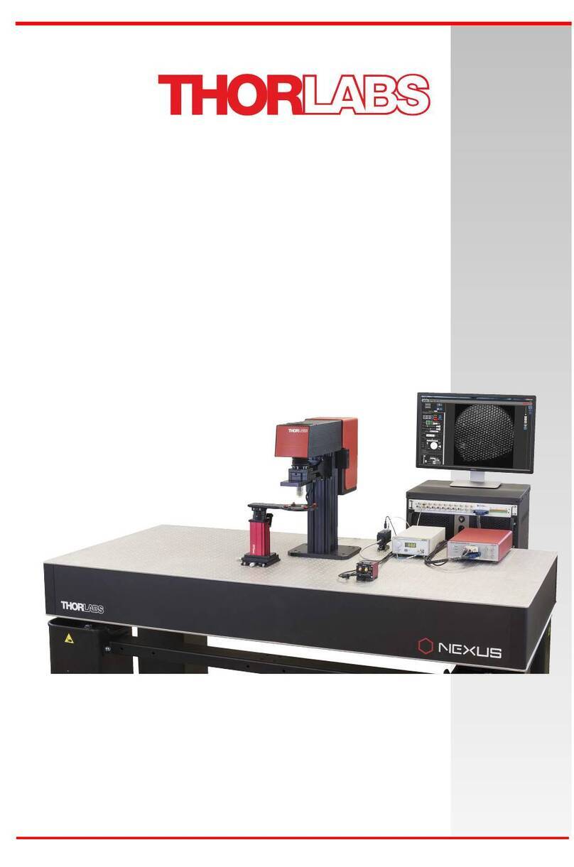
Cerna® Mini Microscopes
User Guide

Cerna Mini Microscopes
Table of Contents
Chapter 1 Warning Symbol Definitions............................................................ 1
Chapter 2 Safety................................................................................................. 2
Chapter 3 Description........................................................................................ 3
3.1 Features at a Glance.............................................................. 3
3.2 Overview................................................................................. 4
Chapter 4 Getting Started.................................................................................. 7
4.1 Ordering Codes...................................................................... 7
4.2 Unpacking and Inspection.................................................... 7
4.3 Cerna Mini Microscope Setup............................................... 9
4.3.1 Microscope.................................................................. 9
4.3.2 Fluorescence Filter Installation.................................. 12
4.3.3 LED Power Source Installation.................................. 13
4.3.4 Camera ..................................................................... 14
Chapter 5 Maintaining the SFM Series........................................................... 15
5.1 Cleaning................................................................................ 15
Chapter 6 Specifications................................................................................. 16
6.1 Microscope Body Specifications........................................ 16
6.2 Camera Port ......................................................................... 16
6.3 Motorized XYZ Translation.................................................. 16
6.4 Motion Controller................................................................. 17
6.5 LED Collimation Module Compatibility
(SFM/SFMGFP/SFMGFP2)................................................... 18
6.6 LED Specifications (SFMGFP/SFMGFP2).......................... 18
6.7 T-Cube LED Driver Specifications...................................... 18
6.8 Fluorescence Filter Specifications (SFMGFP/SFMGFP2). 20
6.9 Objective Specifications (SFMGFP/SFMGFP2) ................. 20
6.10 Monochrome CCD Camera Specifications (SFMGFP)...... 21
6.11 sCMOS Camera Specifications (SFMGFP2) ...................... 25
Chapter 7 Mechanical Drawings..................................................................... 27

Cerna Mini Microscopes
Chapter 8 Warranty.......................................................................................... 35
Chapter 9 Regulatory....................................................................................... 36
Chapter 10 Thorlabs Worldwide Contacts..................................................... 37

Cerna Mini Microscopes Chapter 1: Warning Symbol Definitions
Rev. D, July 9, 2018 Page 1
Chapter 1 Warning Symbol Definitions
Below is a list of warning symbols you may encounter in this manual or on your
device.
Symbol
Description
Direct Current
Alternating Current
Both Direct and Alternating Current
Earth Ground Terminal
Protective Conductor Terminal
Frame or Chassis Terminal
Equipotentiality
On (Supply)
Off (Supply)
In Position of a Bi-Stable Push Control
Out Position of a Bi-Stable Push Control
Caution: Risk of Electric Shock
Caution: Hot Surface
Caution: Risk of Danger
Warning: Laser Radiation
Caution: Spinning Blades May Cause Harm

Cerna Mini Microscopes Chapter 2: Safety
Page 2 TTN109666-D02
Chapter 2 Safety
All statements regarding safety of operation and technical data in this user guide
will only apply when the unit is operated correctly. Refer to the relevant User Guide
of the individual product for safety instructions. Please read the following warnings
and cautions carefully before operating the unit.
WARNING
DO NOT use the device for anything other than its intended use. If the
device is used in a manner not specified by Thorlabs, the protection
provided by the equipment may be impaired.
CAUTION
DO NOT operate in a wet, damp, or explosive environment.

Cerna Mini Microscopes Chapter 3: Description
Rev. D, July 9, 2018 Page 3
Chapter 3 Description
The Cerna Mini Microscopes provide simple microscope configurations that are
ideal for experiments requiring simple imaging. Thorlabs offers four microscope
configurations: SFM2 (Cerna Mini Microscope), SFM (Cerna Mini Microscope with
Epi-Illuminator Module), SFMGFP (Cerna Mini Microscope with Epi-Illuminator
Module for GFP/Alexa Fluor® 488 with CCD Camera), and SFMGFP2 (Cerna Mini
Microscope with Epi-Illuminator Module for GFP/Alexa Fluor® 488 with sCMOS
Camera).
The SFM2 consists of a motorized microscope body and camera port. Similarly,
SFM, consists of the same base components with the addition of an illumination
cube housing module (WFA2002). Both allow you to add your own camera, filter
cube, and light source to suit your experimental needs. The motorized objective
holder provides 1" of vertical focusing adjustment for the 10X objective. The
motorized Microscope Body has ample space beneath the objective for adding
sample stages. The C-Mount threaded Camera Port is compatible with most
industry-standard cameras.
The SFMGFP and SFMGFP2 microscopes each consist of a motorized
microscope body, a camera port, a filter cube, a light source, an LED collimation
module, an objective, a scientific camera, and an LED driver.
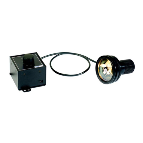
The epi-illuminator module accepts a variety of Thorlabs’ mounted LEDs.
Currently, we offer two types of LED collimation modules (SFM22 and SFM80) to
connect the LEDs to the epi-illuminator module. The SFMGFP and SFMGFP2
each ship with an SFM80 module. For two LED collimation modules, replace the
SFM Epi adapter at the rear of the WFA2002 module with a DFM1 fluorescence
filter cube, a C4W-CC cage cube connector, and an SM1CP2 end cap.
3.1 Features at a Glance
Cerna Mini Features
oMicroscope Body Uses 66 mm Optical Rail, Enabling the
Addition of Custom Modules
o1" of Motorized Microscope Translation in X and Y Axes
oMicroscope Body with 6" Throat Depth
oCoarse Objective Height Adjustment of 6.38"
Additional SFM Microscope Feature
oEpi-illumination filter cube housing (WFA2002)
Additional SFMGFP/SFMGFP2 Microscope Features
oDetection
SFMGFP: 1.4 Megapixel Monochrome Scientific-
Grade CCD Camera
SFMGFP2: 2.1 Megapixel Monochrome sCMOS
Scientific Camera
Connects to 1X Magnification Camera Tube with C-
Mount Threads
2/3" Sensor Format (11 mm Diagonal)
Cerna Mini Microscopes Chapter 3: Description
Page 4 TTN109666-D02
o10X Magnification Objective
oFilter Cube with Filter Set for GFP
oEpi-Illuminator Module for LED with 80° to 120° Divergence
Angle
oBlue LED for GFP Excitation
470 nm Nominal Wavelength
710 mW Typical Output Power at Max Current
25 nm FWHM (Full Width at Half Max) Bandwidth
3.2 Overview
Figure 1 SFM Microscope
3-Axis Controller
Box
3-Axis
Knob Box
Filter Cube Housing
Camera Port
Focus
Module
3-Axis
Controller Box

Cerna Mini Microscopes Chapter 3: Description
Rev. D, July 9, 2018 Page 5
Figure 2 SFM2 Microscope
Figure 3 SFMGFP Microscope
3-Axis
Controller
Box
3-Axis Controller
Box
3-Axis
Knob Box
LED
Filter Cube Housing
N10X-PF
T-Cube
LED Driver
Camera Port
SFM80
Monochrome Gig-E Camera
Focus
Module
T-Cube
LED Driver
3-Axis
Knob Box
Focus
Module
Camera Port
3-Axis
Controller
Box

Cerna Mini Microscopes Chapter 3: Description
Page 6 TTN109666-D02
Figure 4 SFMGFP2 Microscope
3-Axis
Controller
Box
3-Axis Controller
Box
3-Axis
Knob
Box
LED
Filter Cube Housing
N10X-PF
T-Cube
LED Driver
Camera Port
SFM80
Focus
Module
T-Cube
LED Driver
sCMOS Camera

Cerna Mini Microscopes Chapter 4: Getting Started
Rev. D, July 9, 2018 Page 7
Chapter 4 Getting Started
This section is provided for those interested in getting the Cerna Mini Microscopes
up and running quickly.
4.1 Ordering Codes
Ordering Codes
Description
SFM
Cerna Mini Microscope with Epi-Illuminator Module
SFM2
Cerna Mini Microscope
SFMGFP
Cerna Mini Microscope with Epi-Illuminator Module for
GFP/Alexa Fluor® 488 with CCD Camera
SFMGFP2
Cerna Mini Microscope with Epi-Illuminator Module for
GFP/Alexa Fluor® 488 with sCMOS Camera
SFM22
22° Collimating Tube with XY Adjustment
SFM80
80° Collimating Tube with XY Adjustment
4.2 Unpacking and Inspection
Open the package, and carefully remove the Cerna Mini Microscope and its
accessories. The table lists the standard accessories shipped with the device.

Cerna Mini Microscopes Chapter 4: Getting Started
Page 8 TTN109666-D02
Name
Quantity
SFM
SFM2
SFMGFP
SFMGFP2
Microscope Body with PLS-XY Stage
and Motorized Objective Mount
1
1
1
1
3-Axis Controller with Motorized
Stage Control Box (Item # MCM3001)
1
1
1
1
Filter Cube Housing (Item #
WFA2002)
1
-
1
1
1X Camera Port (Item # WFA4100)
1
-
1
1
MDF-GFP Filter Set
-
-
1
1
T-Cube LED Driver (Item # LEDD1B)
-
-
1
1
T-Cube Power Supply (Item #
KPS101)
-
-
1
1
Monochrome Gig-E Camera
(Item # 1501M-GE)
-
-
1
-
sCMOS Camera (Item # CM2100M-
USB)
-
-
-
1
80° Collimating Tube with XY
Adjustment (Item # SFM80)
-
-
1
1
Nikon Plan Fluorite Imaging
Objective (Item # N10X-PF)
-
-
1
1
LED, Blue 470 nm (Item # M470L3)
-
-
1
1
OEM Microscopy Filter Cube
(Item # MDFM-MF2)
-
-
1
1
M6 Socket Head Cap Screw
8
6
8
8
1/4"-20x1/2" Socket Head Cap Screw
8
6
8
8
Name
Quantity
SFM
SFM2
SFMGFP
SFMGFP2
M6 Flat Washer
8
6
8
8
LED Driver Operation Manual
-
-
1
1
Thorlabs Digital Camera Quick Start
Guide
-
-
1
1
ThorCam Camera Software CD
-
-
1
1
MCM3000 Series 3-Axis Controller User
Guide
1
1
1
1
Inspect the device and its accessories for any missing parts or damage. If there is
any problem, please contact our nearest office (see Thorlabs Worldwide
Contacts on page 37 for details).

Cerna Mini Microscopes Chapter 4: Getting Started
Rev. D, July 9, 2018 Page 9
4.3 Cerna Mini Microscope Setup
Note: To set up the SFM and SFM2 microscopes, follow the procedure in Section
4.3.1. For full functionality, the SFM will require the user to purchase an objective,
light source, filter cube, fluorescence filter set, collimator and digital camera. The
SFM2 will require an objective, light source, and digital camera.
Requirements: The following additional accessories (not included) are required
for installation of the microscope:
1.5 mm Hex Key
2 mm Hex Key
2.5 mm Hex Key
5/64" Hex Key
4.3.1 Microscope
1. Use four SHCS (Socket Head Cap Screw) (M6 for metric, 1/4"-20 x 1/2"
for imperial) and washers to mount the Microscope Body onto the optical
table/breadboard.
2. Use a 5/64" hex key to remove the three shipping plates on the
Microscope Body.
Figure 5 Removing the Shipping Plates
3. Skip this step for SFM2. For SFM, use a 2 mm hex key to mount the Filter
Cube Housing onto the Dovetail Plate.
Shipping Plates (3X)
18 X 2-56 x 1/4"
Screws

Cerna Mini Microscopes Chapter 4: Getting Started
Page 10 TTN109666-D02
Figure 6 Mounting the Filter Cube Housing
4. For SFM, use the 2 mm hex key to mount the Camera Port onto the Filter
Cube Housing. For SFM2, mount the Camera Port directly to the Dovetail
Plate.
Figure 7 Mounting the Camera Port
5. Use two SHCS to mount the 3-Axis Controller Box onto the optical
table/breadboard. (Refer to MCM3000 Series 3-Axis Controller User
Guide for setup.)
M4 x 12 mm Screw
M4 x 12 mm Screw

Cerna Mini Microscopes Chapter 4: Getting Started
Rev. D, July 9, 2018 Page 11
6. Connect the adapter cables from the Focus Module and PLS-XY Stage to
the 3-Axis Knob Box.
7. Connect the cable from the 3-Axis Knob Box to the 3-Axis Controller Box.
8. Connect the power supply from the 3-Axis Controller Box to a standard
power outlet.
9. Mount the objective (included with SFMGFP and SFMGFP2 only) onto the
microscope.

Cerna Mini Microscopes Chapter 4: Getting Started
Page 12 TTN109666-D02
4.3.2 Fluorescence Filter Installation
The SFMGFP and SFMGFP2 each ship with an MDF-GFP filter.
Note: The SFM module does not come with a filter cube nor a filter set. Use filter
cube item # MDFM-MF2 to install your filter set in the Filter Cube Housing.
To install the MDF-GFP filter:
Figure 8 Replacing the Filter Set
1. Use a 1.5 mm hex key to remove the screws (2X) from either side of the
Filter Cube Housing cover.
2. Use a 2.5 mm hex key to loosen the screw at the center of the cover to
slide out the filter cube.
3. Install your filter set inside the filter cube. See the MDFM-MF2 manual for
detailed instructions- https://www.thorlabs.com/manuals.cfm
4. Slide the filter cube on the Filter Cube Housing cover and tighten the
screw at the center of the cover.
2X M2 x 5 mm
Screws
M3 x 10 mm
Screw

Cerna Mini Microscopes Chapter 4: Getting Started
Rev. D, July 9, 2018 Page 13
4.3.3 LED Power Source Installation
For easy installation, the Filter Cube Housing included in the SFMGFP and
SFMGFP2 configurations comes with a pre-installed LED and SFM80 collimation
tube.
1. Use two SHCS to mount the T-Cube LED Driver onto the optical
table/breadboard.
2. Connect the LED to the T-Cube LED Driver.
3. Connect the power supply from the T-Cube LED Driver to a standard
power outlet.

Cerna Mini Microscopes Chapter 4: Getting Started
Page 14 TTN109666-D02
4.3.4 Camera
Mount the camera (Monochrome Gig-E camera for SFMGFP or sCMOS camera
for SFMGFP2) on the Camera Port. Refer to the included camera user guide for
setup and installation.
Figure 9 Mounting the Camera

Cerna Mini Microscopes Chapter 5: Maintaining the SFM Series
Rev. D, July 9, 2018 Page 15
Chapter 5 Maintaining the SFM Series
There are no serviceable parts in the SFM series modules. If you suspect a
problem with your module, please contact our nearest office (see Thorlabs
Worldwide Contacts on page 37 for details) for assistance from an applications
engineer.
5.1 Cleaning
Refer to the relevant section in the User Guide of individual products for cleaning
and maintenance.
WARNING
Disconnect the power supply before cleaning the unit to prevent any
injuries.
CAUTION
DO NOT expose the unit to spray, liquids, or solvents. This may
damage the unit.
Use a damp lint-free cloth to clean the microscope body.

Cerna Mini Microscopes Chapter 6: Specifications
Page 16 TTN109666-D02
Chapter 6 Specifications
6.1 Microscope Body Specifications
Specification
Value
Rail Length
174.3 mm (6.86")
Post Length
200 mm (7.87")
Post Manual Height Adjustment
162 mm (6.38”)
Throat Depth
152.4 mm (6")
Fine Motorized Motion
X,Y, and Z Axes
Fine Motorized Total Travel
1″ for Each Axis
Mounting Screw
1/4″-20 or M6
Objective Thread Adapter (Included)
External M32 x 0.75 Threads
Internal M25 x 0.75 Threads
Optional Breadboard (Not Included)
MB1224 or MB3060/M
6.2 Camera Port
Specification
Value
Item #
WFA4100
Magnification
1X
Dovetail
Male D1N
Tube Lens Focal Length
200 mm
Camera Threading
C-Mount (1.00″-32)
6.3 Motorized XYZ Translation
Specification
Value
Travel Range
25.4 mm (1") for Each Axis
Bidirectional Repeatability
1 µm
Backlash
1 µm
Minimum Achievable Incremental
Movement
100 nm
Minimum Achievable Repeatable
Movement
200 nm
Velocity (Max)
7 mm/s
Acceleration (Max)
11 mm/s2
Cable Length
6ꞌ (1.8 m)

Cerna Mini Microscopes Chapter 6: Specifications
Rev. D, July 9, 2018 Page 17
Stepper Motor Specifications
Thread Screw Pitch
0.3 mm
Step Angle
1.8°
Limit Switches
Hall Effect Sensors
Phase Current
0.49 A
Phase Resistance
5.1 Ω
Phase Inductance
1.5 mH
Insulation Resistance
20 MΩ
6.4 Motion Controller
Specification
Value
Item #
MCM3001
Motor Output
Motor Drive Voltage
24 V
Motor Drive Current
7.0 A (Peak)
3.0 A (RMS)
Motor Drive Type
12-Bit PWM Control
Control Algorithm
Open-Loop Microstepping
Stepping
64 Microsteps per Full Step
Encoder Resolution
0.212 µm
Total Steps per Revolution
12800
Maximum Stepping Velocity
4577 steps/s
Position Feedback
Quadrature Encode (QEP) Input, 5 V
Encoder Feedback Bandwidth
16 MHz
Position Counter
32-Bit
Operating Modes
Position and Velocity
Velocity Profile
Trapezoid
Motor Drive Connector
Mechanical Specifications
15 Position D-Type, Micro-D Plug, Male Pin
Connector
Motor Drive Outputs
200
Quadrature Encoder (QEP) Input
Single Ended
Limit Switch Inputs
Forward, Reverse, Index
Encode Supply
5 V
Input Power Requirements
Voltage
24 VDC
Current
3.75 A (Peak)
This manual suits for next models
4
Table of contents
Other THORLABS Microscope manuals

THORLABS
THORLABS CM100 User manual

THORLABS
THORLABS Cerna CM501 User manual

THORLABS
THORLABS CM100 User manual

THORLABS
THORLABS TLV-U-FF User manual

THORLABS
THORLABS FS200 User manual

THORLABS
THORLABS CM100 User manual

THORLABS
THORLABS LEDD1 User manual

THORLABS
THORLABS LDCCM User manual

THORLABS
THORLABS CM201 User manual

THORLABS
THORLABS MLS203 Series User manual