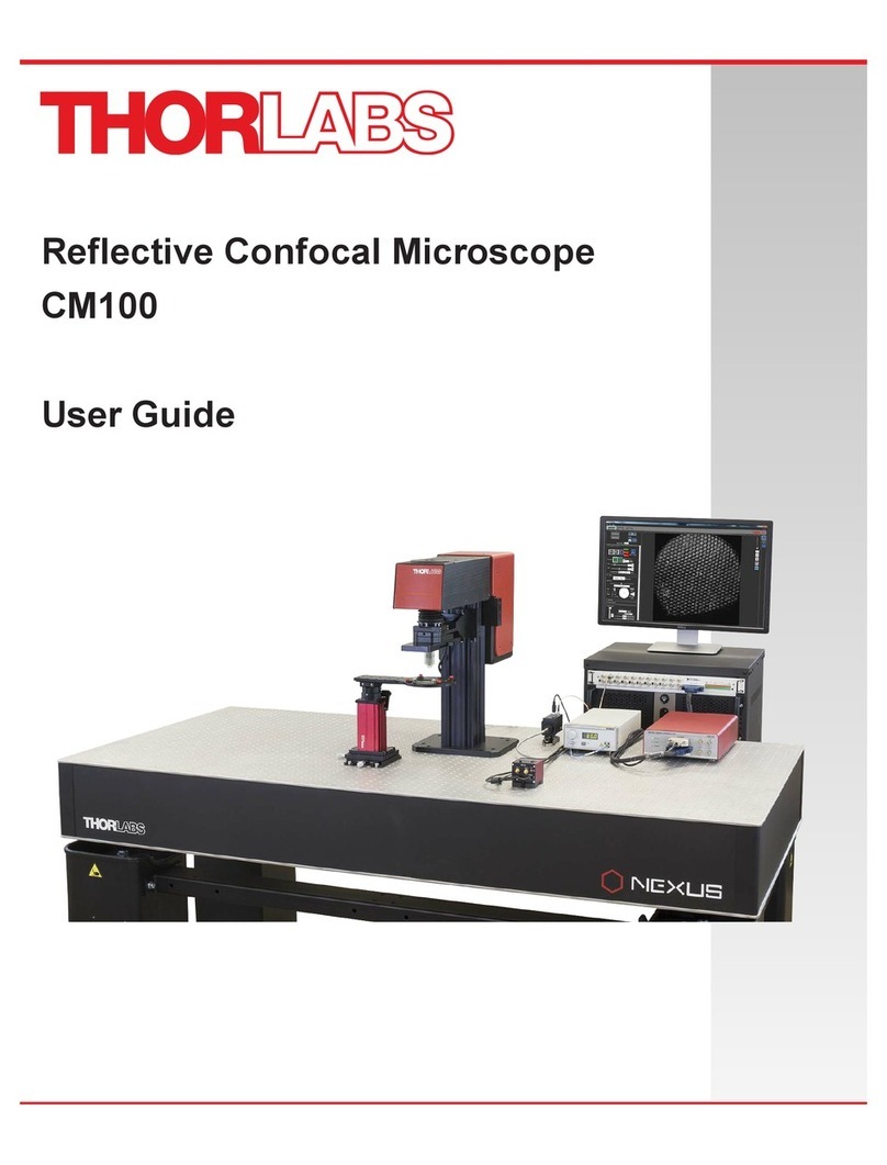
THORLABS CM100 User manual

CM100
Reflective Confocal
Microscope
User Guide


Copyright © January 28, 2022 Thorlabs, Inc. All rights reserved.
Information in this document is subject to change without notice. The software described in this document is furnished under a
license agreement or nondisclosure agreement. The software may be used or copied only in accordance with the terms of
those agreements. No part of this publication may be reproduced, stored in a retrieval system, or transmitted in any form or
any means electronic or mechanical, including photocopying and recording for any purpose other than the purchaser’s
personal use without the written permission of Thorlabs, Inc.
Thorlabs, Inc.
108 Powers Court
Sterling, VA 20166
703-651-1700


CM100 Reflective Confocal Microscope
Table of Contents
Chapter 1 Warning Symbol Definitions.............................................................................................1
Chapter 2 Safety...................................................................................................................................2
Chapter 3 Description .........................................................................................................................3
3.1. Features at a Glance..................................................................................................... 3
3.2. Imaging Capabilities..................................................................................................... 3
Chapter 4 Getting Started...................................................................................................................4
4.1. Unpacking and Inspection ........................................................................................... 4
4.2. Setting up the CM100................................................................................................... 5
4.3. Cable Connection Diagram.......................................................................................... 8
4.3.1. Electronic Control Unit (ECU) Connections..........................................................................8
4.3.2. Galvo-Galvo Scanning Pair.................................................................................................10
Chapter 5 Alignment..........................................................................................................................12
5.1. Widefield Imaging....................................................................................................... 21
Chapter 6 Maintaining the CM100....................................................................................................22
6.1. Cleaning...................................................................................................................... 22
6.2. Connector Cleaning.................................................................................................... 22
6.3. Troubleshooting ......................................................................................................... 22
Chapter 7 Specifications...................................................................................................................23
Chapter 8 Mechanical Drawing........................................................................................................25
Chapter 9 Regulatory ........................................................................................................................26
Chapter 10 Thorlabs Worldwide Contacts........................................................................................27
CM100 Reflective Confocal Microscope Chapter 1: Warning Symbol Definitions
Rev F, January 28, 2022 Page 1
Chapter 1 Warning Symbol Definitions
Below is a list of warning symbols you may encounter in this manual or on your device.
Symbol
Description
Direct Current
Alternating Current
Both Direct and Alternating Current
Earth Ground Terminal
Protective Conductor Terminal
Frame or Chassis Terminal
Equipotentiality
On (Supply)
Off (Supply)
In Position of a Bi-Stable Push Control
Out Position of a Bi-Stable Push Control
Caution: Risk of Electric Shock
Caution: Hot Surface
Caution: Risk of Danger
Warning: Laser Radiation
Caution: Spinning Blades May Cause Harm

CM100 Reflective Confocal Microscope Chapter 2: Safety
Page 2 TTN118785-D02
Chapter 2 Safety
All statements regarding safety of operation and technical data in this user guide will only apply when the unit is
operated correctly. Refer to the relevant User Guide of the individual product for safety instructions. Please read
the following warnings and cautions carefully before operating the device.
WARNING
DO NOT use the device for anything other than its intended use. If the device is used in a manner not
specified by Thorlabs, the protection provided by the equipment may be impaired.
WARRANTY WARNING
DO NOT open the scanner block, electronics enclosure, detector module, or computer. There are no
serviceable parts in these products. DO NOT perform instrumentation maintenance or service except
as specifically stated. Any modification or servicing of this system by unqualified personnel renders
Thorlabs free of any liability. Only personnel authorized by Thorlabs and trained in the maintenance
of this equipment should remove any covers or housings or attempt any repairs or adjustments.
CAUTION
The computer supplied with this system requires configuration for specific AC line voltages of
110 VAC or 230 VAC nominal. Refer to the computer’s User Guide for details.
WARNING
DO NOT operate in a wet, damp, or explosive environment.
WARNING
In case of software failure, turn off the laser source.

CM100 Reflective Confocal Microscope Chapter 3: Description
Rev F, January 28, 2022 Page 3
Chapter 3 Description
Thorlabs’ Entry-Level Upright Reflective Confocal Microscope is a complete single-channel system. By eliminating
signals that originate from outside the focal plane, confocal microscopy provides the ability to acquire high-
resolution, optically sectioned images from within a thick sample. The CM100 supports reflected-light confocal
imaging for viewing the surface structure of biological samples or for inspections of applications.
The CM100 has a 35 mm x 52 mm x 3 mm silver-coated mirror at the front of the scan path that directs light from
the scanners to the objective. In order to use this microscope for widefield as well as confocal imaging, you can
replace the mirror with a beamsplitter. The CM100 is designed to provide a cost-effective entry point to owning a
modular confocal microscope that can be upgraded to an advanced confocal microscope.
3.1. Features at a Glance
•Upright Microscope Based on the Cerna DIY Microscopy Platform
o95 mm Dovetail on Rail Accepts Cerna Accessories
oD1N Dovetail on Top of Scan Path for Cerna Widefield Imaging Modules
•Confocal Scan Path with Galvo-Galvo Scanners
•One Benchtop Excitation Laser (660 nm SM Laser)
•One Multialkali Photomultiplier Tube (PMT)
•Filter Set for Reflected-Light: One Beamsplitter, One Quarter-Wave Plate, and Two Polarizers
•20X Olympus Objective
•PC with DAQ and ThorImage®LS Software
3.2. Imaging Capabilities
•Full Frame 4096 x 4096 Pixel Images (Uni-Directional Scan)
•2 FPS for 512 x 512 Pixel Bi-Directional Scans
•Galvo-Galvo Scan Head with 1.0 to 10 s Pixel Dwell Times
•796 µm x 796 µm Field of View (FN25)

CM100 Reflective Confocal Microscope Chapter 4: Getting Started
Page 4 TTN118785-D02
Chapter 4 Getting Started
This section is provided for those interested in getting the Reflective Confocal Microscope up and running quickly.
4.1. Unpacking and Inspection
Open the package, and carefully remove the CM100 and its accessories. Unpack the laser, Galvo-Galvo Controller,
PMT, computer, and monitor from their respective packages. The table lists the standard accessories shipped with
the device.
Name
Quantity
Reflective Confocal Microscope
1
20X Microscope Objective (RMS20X)
1
NI Breakout Box
1
K-Cube Stepper Driver (KST101)
1
K-Cube Power Supply
1
Laser (S1FC660)
1
Galvo-Galvo Controller (LSKGG4)
1
Photomultiplier Tube (PMT1001/M)
1
Computer with Monitor, Keyboard, and Mouse
1
Clamping Fork (CF175)
1
Post Holder (PH082E)
1
Optical Post (TR20/M)
1
NI SHC68-68-EPM Cable
1
NI SH6868 Cable
1
Polarization-Maintaining Patch Cable (P1-630PM-FC-2)
1
Armored Fiber Patch Cable
1
Beamsplittera(BSW10R)
1
Polarizersa(LPVISE100-A)
2
Quarter-Wave Plate (WPQ10E-670)
1
K-Cube USB Cable
1
SMA to BNC Cable
1
Alignment Tool
1
Grid Slide (R1L3S3P)
1
M6 x 16 mm Socket Head Cap Screw
12
1/4-20 x 5/8" Socket Head Cap Screw
12
M6 Flat Washer
6
2 mm Hex Wrench
1
2.5 mm Hex Wrench
1
5 mm Hex L-Key
1
2 mm Hex L-Key
1
1.5 mm Hex Wrench
1
3/32" Hex L-Key
1
3/16" Hex L-Key
1
a. The filter set comes pre-installed on the microscope.
Inspect the device and its accessories for any missing parts or damage. If there is any problem, please contact our
nearest office (see the Thorlabs Worldwide Contacts Chapter on Page 27 for details).

CM100 Reflective Confocal Microscope Chapter 4: Getting Started
Rev F, January 28, 2022 Page 5
4.2. Setting up the CM100
CAUTION
DO NOT place the SMA to BNC cable or DB-25 Connector cable near any electrical noise sources
such as a power cable. This may cause poor quality images.
A. Microscope
1. Use four screws (M6 for metric, 1/4-20 x 5/8" for imperial) to mount the CM100 onto the optical table.
See the Mechanical Drawing Chapter on Page 25 for mounting holes.
2. Use the 2 mm hex wrench to remove the shipping plate on the objective arm.
3. Use two screws and washers to mount the K-Cube Stepper Motor Controller onto the optical table.
4. Connect the cable from the Motorized Objective Arm to the Motor port on the K-Cube Stepper Motor
Controller.
5. Connect the K-Cube Power Supply to a standard power outlet.
6. Connect one end of the USB cable to the K-Cube Stepper Driver Controller and the other end to the
computer.
B. Computer
1. Setup the computer, monitor, keyboard, and mouse.
2. Connect one end (silver) of the NI SHC68-68-EPM cable to the computer (Connector 0) and the other
end (blue) to the rear panel of the NI Breakout Box.
3. Connect one end of the NI SH6868 cable to the NI Breakout Box and the other end to DAQ port of the
Galvo-Galvo Controller.

CM100 Reflective Confocal Microscope Chapter 4: Getting Started
Page 6 TTN118785-D02
C. Galvo-Galvo Controller
1. Connect the DB-25 Connector cable to the Scanner port of the Galvo-Galvo Controller and the other
end to the Scanner Controller port of the CM100.
2. Connect the power cord to a standard power outlet.
D. Laser
Read the Laser User Guide included along with the unit before setting up the laser.
WARNING
DO NOT switch on the laser while installing the Confocal system. This may cause injury due to laser
radiation. Make sure the laser source is off.
1. Remove the red cap from the CM100 back panel.
2. Connect one end of the PM (Polarization-Maintaining) Patch cable to the laser and the other end to
the CM100 back panel.
Make sure to align the key on the patch cable connector with the key slot on the fiber bulkhead before
connecting the cable.
3. Connect the power cord to a standard power outlet.

CM100 Reflective Confocal Microscope Chapter 4: Getting Started
Rev F, January 28, 2022 Page 7
E. PMT
1. Use the post holder and clamping fork to mount the PMT onto the optical table.
2. Connect the USB port to the computer.
3. Connect the SMA to BNC cable from the OUT port of the PMT to the AI1 port on the NI Breakout Box.
4. Connect one end of the Armored Fiber Patch cable to the PMT and the other end to the Pinhole port
of the CM100.

CM100 Reflective Confocal Microscope Chapter 4: Getting Started
Page 8 TTN118785-D02
4.3. Cable Connnection Diagram
4.3.1. Electronic Control Unit (ECU) Connections
Figure 4-3.1 Electronic Control Unit (ECU), Rear View

CM100 Reflective Confocal Microscope Chapter 4: Getting Started
Rev F, January 28, 2022 Page 9
ECU IO
| X IN: This is the command signal for the x galvanometer. It is not used in Thorlabs’ complete imaging systems
setups. It may be monitored without interrupting the system, so long as the impedance is 1 kΩ.
| Y IN: This is the command signal for the y galvanometer. It may be monitored without interrupting the system, so
long as the impedance is 1 kΩ.
| X OUT: This is a monitor signal that indicates the location of the x Galvo. It may be monitored without
interrupting the system, so long as the impedance is 1 kΩ.
| Y OUT: This is a monitor signal that indicates the location of the y Galvo. It may be monitored without
interrupting the system, so long as the impedance is 1 kΩ.
To access the scanning IO signals, a BNC2090A pass-through box is placed between the Galvo-resonant
controller and the computer. The IO is shown below:
Figure 4-3.2 Input/Output Signals from the Electronic Control Unit

CM100 Reflective Confocal Microscope Chapter 4: Getting Started
Page 10 TTN118785-D02
4.3.2. Galvo-Galvo Scanning Pair
With Galvo-Galvo systems there are two galvos, a fast (X axis) Galvo and a slow (Y axis) Galvo. The fast Galvo
moves across the image linearly, with even velocity. It takes 200 µs to turnaround at the edges of the image. There
is a turnaround at each side of the image. The slow Galvo (Y axis) controls line movement, there is a flyback
between images.
The Line trigger is synchronized to the fast X Galvo, triggering on the acquisition, and going to zero during the
turnarounds. This line trigger synchronization is true for both bi-directional (two-way) and uni-directional (one-way)
acquisition.

CM100 Reflective Confocal Microscope Chapter 4: Getting Started
Rev F, January 28, 2022 Page 11
The slow Y Galvo moves once per image frame. During each sweep of the Y Galvo scanner, the ECU signals a
frame trigger (FRAME TRIGGER OUT or vertical line sync) for acquisition synchronization.

CM100 Reflective Confocal Microscope Chapter 5: Alignment
Page 12 TTN118785-D02
Chapter 5 Alignment
You must align the microscope before imaging. There are two Alignment procedures: Illumination Alignment and
Grid Slide Alignment.
A. Illumination Alignment
Perform the Illumination Alignment procedure prior to Grid Slide Alignment.
1. Use the 2.5 mm hex wrench to remove the red front and back cover of the microscope.
There are six M4 screws on the back cover, and one M4 screw on the front cover of the microscope.
To use the microscope for widefield imaging, see the Widefield Imaging Section on Page 21.
2. Use a 2 mm hex key to remove the dovetail cover on top of the microscope.
3. Use the slider tool on the objective holder to move it to its rear position, and then attach the Alignment
tool to the front port of the objective arm.

CM100 Reflective Confocal Microscope Chapter 5: Alignment
Rev F, January 28, 2022 Page 13
4. Turn on all devices.
For the laser, turn the POWER key switch clockwise. The unit is ON when the display lights up. DO
NOT activate the laser at this step.
5. Use the PWR ADJUST knob on the laser to set it to maximum power.
6. Open the ThorImageLS application, and select the hardware components you have setup in the
Hardware Setup window.
The Hardware Setup window appears when you open the ThorImageLS application. Alternatively,
you can access it from the main screen of the application. Click on the
icon on the Menu panel to open the Hardware Setup window.
Make sure that a green dot appears next to the components that are relevant to your hardware setup.
A red dot appears if the device is not present or unable to communicate.

CM100 Reflective Confocal Microscope Chapter 5: Alignment
Page 14 TTN118785-D02
7. In the Galvo/Galvo Area Control panel, select Advanced and click
8. Press and release the ENABLE switch to activate the laser.
The LASER ON indicator lights up and after a delay of approximately 5 seconds, the source begins to
emit light.
9. Use a 2 mm hex wrench to adjust the tip and tilt of the Mirror Mount to center the beam on the IR Disk
of the Alignment tool.
Use the iris on the Alignment tool to resize the beam on the center of the IR Disk. If the beam on the
IR Disk appears clipped (not circular), please contact Thorlabs for assistance.
WARNING
DO NOT stare into the laser beam. Avoid direct eye contact. Wear protective laser eyewear. Use
proper laser safety procedures. Consult with your organization’s laser safety officer for
recommendations.

CM100 Reflective Confocal Microscope Chapter 5: Alignment
Rev F, January 28, 2022 Page 15
10. Press and release the ENABLE switch to turn off the laser.
11. Remove the Alignment tool.
12. Place a piece of paper at the base of the microscope to visualize the beam.
13. Pree and release the ENABLE switch to activate the laser.
14. Use the 2 mm hex key to adjust the XY Mount inside the microscope (the PM Patch cable is
connected to an XY Mount) in X and Y directions to center the hot spot (maximum beam intensity at
the center of the beam).
Note: A cell phone camera can be used to help visualize the hot spot of the beam on the paper.
Other manuals for CM100
2
Table of contents
Other THORLABS Microscope manuals

THORLABS
THORLABS CM100 User manual

THORLABS
THORLABS CM100 User manual

THORLABS
THORLABS MFC1 User manual

THORLABS
THORLABS TLV-U-FF User manual

THORLABS
THORLABS LEDD1 User manual

THORLABS
THORLABS FS200 User manual

THORLABS
THORLABS Cerna CM501 User manual

THORLABS
THORLABS CM201 User manual

THORLABS
THORLABS LDCCM User manual

THORLABS
THORLABS MLS203 Series User manual