THORLABS LDCCM User manual

LDCCM
Digital Microscope &
Tablet Mount Kit for
LDC401(A) Fiber Cleavers
User Guide

Microscope and Tablet Mount Kit
Table of Contents
Chapter 1Description........................................................................1
1.1.Introduction...................................................................1
1.2.PartsChecklist...............................................................1
Chapter 2Setup.................................................................................. 2
2.1.Hardware......................................................................2
2.2.PositioningtheCamera..................................................6
Chapter 3Specifications ...................................................................8
Chapter 4Regulatory.........................................................................9
Chapter 5Thorlabs Worldwide Contacts.......................................10

Microscope and Tablet Mount Kit Chapter 1: Description
Rev A, November 2, 2018 Page 1
Chapter 1 Description
1.1. Introduction
The LDCCM kit enables users of Thorlabs' LDC401 or LDC401A Large-Diameter
Fiber Cleavers to view a magnified image of the fiber, micrometer backstop, and
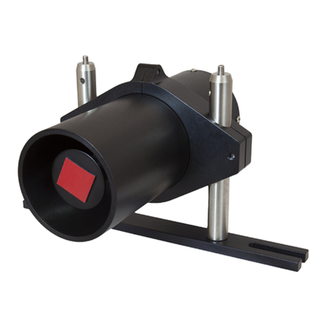
cleave blade on their tablet controller screen. It includes a USB microscope
camera mounted on a swing-arm assembly which makes it easy to position the
camera over the fiber or move it out of the way. It also includes a mast with a USB
hub, which makes it possible to mount the tablet controller above the cleaver and
use the tablet controller as a display for the camera (as well as a controller for the
cleaver).
1.2. Parts Checklist
When unpacking the LDCCM for the first time, check to be sure that you have the
following:
Camera
Swing Arm Assembly
Tablet Mast
Data Cable (Short USB Cable, Type A to Type B)
Power Cable (USB Cable, Type A to Micro-B)
Four 4-40 x 1/4" Screws and Two 4-40 x 5/8" Screws (3/32" Hex)
If you are missing any of the above or need replacements, please contact
System Components

Microscope and Tablet Mount Kit Chapter 2: Setup
Page 2 TTN164003-D02
Chapter 2 Setup
2.1. Hardware
1. Remove the two screws towards the
back of the right side of the cleaver
using a 3/32" hex key. Save the screws
in case you want to use the cleaver
without the swing arm some time in the
future.
2. Attach the swing arm to the cleaver as
shown, using the two 4-40 x 5/8" long
screws. Use the 3/32" hex key to
tighten the screws.
3. Attach the mast to the back of the
cleaver as shown, using the four 4-40 x
1/4" long screws. Again, use the 3/32"
hex key to tighten the screws.
4. Plug the type A end of the short USB
cable into the bottom USB port in the
mast.
5. Plug the type B end of the short USB
cable into the data port of the cleaver as
shown.

Microscope and Tablet Mount Kit Chapter 2: Setup
Rev A, November 2, 2018 Page 3
6. Remove the two screws at the top of
the mast using the 3/32" hex key.
7. Place the tablet on the mast's cradle.
To allow the tablet to fit in the cradle, it
may be necessary to loosen the two
screws holding the cradle in place.
8. Place the top clamp over the top of the
tablet as shown.
9. Replace the two screws removed from
the top of the mast and capture the top
clamp. Tighten the two screws until the
tablet is secure.
10. Pick up the second (longer) USB cable,
and plug the micro B end into the power
port of the tablet.
11. Plug the other end of the cable into the
USB port at the top left corner of the
cleaver.

Microscope and Tablet Mount Kit Chapter 2: Setup
Page 4 TTN164003-D02
12. Capture the cable in the black clamp at
the back of the mast.
13. Locate the pigtail coming from the USB
hub in the mast and plug it into the
tablet USB port.
14. Remove the digital microscope from its
box and pull the plastic guard off of the
front.
15. Slide the camera into its holder on the
swing arm.
16. Secure the camera cable by pressing it
into the T-slot in the swing arm.

Microscope and Tablet Mount Kit Chapter 2: Setup
Rev A, November 2, 2018 Page 5
17. Plug the end of the camera cable into
the middle USB port in the mast.
18. Bundle up the middle part of the camera
cable.
19. Secure the camera cable using the
hook and loop fastener on the back of
the mast.
The back of the cleaver should now look like this:
Rear View of the Cleaver with Camera and Tablet Mount Installed
Turn on the cleaver using the rocker switch on the back.

Microscope and Tablet Mount Kit Chapter 2: Setup
Page 6 TTN164003-D02
2.2. Positioning the Camera
1. Load an insert into the left fiber holding
block and slide it so that its right end
sits right infront of the cleave blade.
Swing the camera over the end of the
insert.
2. Confirm that the tablet has turned on,
and the GUI has initialized. Press
“Tools” in the tool bar at the bottom of
the tablet screen.
3. Select “Camera.” Rotate the camera
so that objects towards the back
appear on the top of the screen, and
objects towards the front appear at the
bottom of the screen.
4. Zoom in using the silver wheel on the
camera. Focus the camera by
adjusting its position within its holder.
5. If necessary, loosen the two screws in
the middle of the swing arm and adjust
the centering of the camera. Then
readjust the camera position to make
the insert appear horizontal and in
focus. Put the insert in its working
position and make sure there is a right
insert as well.

Microscope and Tablet Mount Kit Chapter 2: Setup
Rev A, November 2, 2018 Page 7
6. Load a fiber into the fiber holding
blocks. Swing the camera over the
fiber. Incrementally lower the camera
and adjust the magnification to get a
good image of the fiber.
7. Advance the micrometer stop so it
comes close to the fiber. Loosen the
two screws in the top of the arm and
adjust the position of the end piece
until the micrometer stop is centered
on the screen. The fiber must be
visible. Rotate the camera within the
holder until the fiber is perfectly
horizontal on the screen. Tighten the
two screws.
8. Advance the micrometer stop to
ensure that there is even contact
across the micrometer stop. That is to
say, the micrometer stop should not be
at an angle with respect to the fiber,
and should touch it on the left at the
same time as the right. If it does not,
use shims to adjust the micrometer
stop.
1. When the camera is not needed, the
swing arm can be rotated
counterclockwise into the storage
position. Use the black post to move it
to avoid altering the camera position
with respect to the bracket.
Microscope and Tablet Mount Kit Chapter 3: Specifications
Page 8 TTN164003-D02
Chapter 3 Specifications
Camera Specifications
Magnification 20X / 220X
Resolution Native: 1600 x 1200 Pixels (2 MP)
With Interpolation: 2560 x 2048 Pixels (5 MP)
Color 24 bit RGB
Focus Range 10 mm to Infinite
Flicker Frequency 50 Hz / 60 Hz
Frame Rate 30 fps Max @ 600 lumens
Shutter Speed 1 ms to 1 s
Video Format AVI
Still Image Format JPG and BMP
White Balance Auto
Exposure Auto
Light Source 8 White Light LEDs, 40 lux
Interface USB 2.0 High Speed
Power Supply 5 VDC from USB Port
Operating System Mac®, Windows®98SE / ME / 2000 / XP / Vista / 7 / 8 / 10
Dimensions Ø33 mm x 112 mm

Microscope and Tablet Mount Kit Chapter 4: Regulatory
Rev A, November 2, 2018 Page 9
Chapter 4 Regulatory
As required by the WEEE (Waste Electrical and Electronic Equipment Directive)
of the European Community and the corresponding national laws, Thorlabs offers
all end users in the EC the possibility to return “end of life” units without incurring
disposal charges.
This offer is valid for Thorlabs electrical and electronic equipment:
Sold after August 13, 2005
Marked correspondingly with the crossed out
“wheelie bin” logo (see right)
Sold to a company or institute within the EC
Currently owned by a company or institute
within the EC
Still complete, not disassembled and not
contaminated
As the WEEE directive applies to self-contained
operational electrical and electronic products, this end of
life take back service does not refer to other Thorlabs products, such as:
Pure OEM products, that means assemblies to be built into a unit by the
user (e.g. OEM laser driver cards)
Components
Mechanics and optics
Left over parts of units disassembled by the user (PCB’s, housings etc.).
If you wish to return a Thorlabs unit for waste recovery, please contact Thorlabs or
your nearest dealer for further information.
Waste Treatment is Your Own Responsibility
If you do not return an “end of life” unit to Thorlabs, you must hand it to a company
specialized in waste recovery. Do not dispose of the unit in a litter bin or at a public
waste disposal site.
Ecological Background
It is well known that WEEE pollutes the environment by releasing toxic products
during decomposition. The aim of the European RoHS directive is to reduce the
content of toxic substances in electronic products in the future.
The intent of the WEEE directive is to enforce the recycling of WEEE. A controlled
recycling of end of life products will thereby avoid negative impacts on the
environment.
Wheelie Bin Logo

Microscope and Tablet Mount Kit Chapter 5: Thorlabs Worldwide Contacts
Page 10 TTN164003-D02
Chapter 5 Thorlabs Worldwide Contacts
USA, Canada, and South America
Thorlabs, Inc.
56 Sparta Avenue
Newton, NJ 07860
USA
Tel: 973-300-3000
Fax: 973-300-3600
www.thorlabs.com
www.thorlabs.us (West Coast)
UK and Ireland
Thorlabs Ltd.
1 Saint Thomas Place
Ely CB7 4EX
Great Britain
Tel: +44 (0) 1353-654440
Fax: +44 (0) 1353-654444
www.thorlabs.com
Europe
Thorlabs GmbH
Hans-Böckler-Str. 6
85221 Dachau / Munich
Germany
Tel: +49-(0) 8131-5956-0
Fax: +49-(0) 8131-5956-99
www.thorlabs.de
Scandinavia
Thorlabs Sweden AB
Bergfotsgatan 7
431 35 Mölndal
Sweden
Tel: +46-31-733-30-00
Fax: +46-31-703-40-45
www.thorlabs.com
France
Thorlabs SAS
109, rue des Côtes
78600 Maisons-Laffitte
France
Tel: +33 (0) 970 444 844
Fax: +33 (0) 825 744 800
www.thorlabs.com
Brazil
Thorlabs Vendas de Fotônicos Ltda.
Rua Riachuelo, 171
São Carlos, SP 13560-110
Brazil
Tel: +55-16-3413 7062
Fax: +55-16-3413 7064
www.thorlabs.com
Japan
Thorlabs Japan, Inc.
3-6-3, Kitamachi,
Nerima-ku, Tokyo 179-0081
Japan
Tel: +81-3-6915-7701
Fax: +81-3-6915-7716
www.thorlabs.co.jp
China
Thorlabs China
Room A101, No. 100, Lane 2891,
South Qilianshan Road
Putuo District
Shanghai 200331
China
Tel: +86 (0) 21-60561122
Fax: +86 (0) 21-32513480
www.thorlabschina.cn

www.thorlabs.com
Table of contents
Other THORLABS Microscope manuals

THORLABS
THORLABS MFC1 User manual

THORLABS
THORLABS Cerna Series User manual

THORLABS
THORLABS CM100 User manual

THORLABS
THORLABS TLV-U-FF User manual

THORLABS
THORLABS LEDD1 User manual

THORLABS
THORLABS CM201 User manual

THORLABS
THORLABS Cerna CM501 User manual

THORLABS
THORLABS MLS203 Series User manual

THORLABS
THORLABS CM100 User manual

THORLABS
THORLABS FS200 User manual