Thursday Pools Waterway Lucky 7 Skimmer 540-8610TP Troubleshooting guide

LUCKY 7 SKIMMER™ FOR FIBERGLASS POOLS
INSTALLATION & OPERATING GUIDE
SKIMMER PART NO.
540-8610TP (White)
540-8617TP (Grey)
TABLE OF CONTENTS
Section
Page
Mounting Skimmer to The Pool Wall………………………
2-3
Operation of Skimmer………………………………………
4
Installation of Optional Equipment…………………………
5
Winterizing Skimmer………………………………………...
5
Trouble Shooting…………………………………………….
6
Dimensions…………………………………………………..
6
Replacement Parts & Accessories…………………………
7

Lucky 7 Fiberglass Inground Pool Skimmer
Installation and Operating Instructions
2 |Page Lucky 7 Skimmer: Installation And Operation Guide
Section 1: Mounting Skimmer to Pool Wall
1) Locate the best position for optimum skimmer performance relative to water flow and wind direction.
Whenever possible avoid placing the skimmer where there are thicker portions of the fiberglass pool
wall like cored portions, lift points, etc…by visually inspecting the backside of the pool prior to
determining final location.
2) Place the flat surface of the faceplate (Part No. TP5193540) on the pool wall. Ensure the top of the
faceplate is level and a maximum 1 inch of the top of the fiberglass pool wall. Once in place, mark and
outline the center opening with a black marker.
3) Cut out pool wall center opening. Cut along the outside of the marked line of the center opening. Refer
to the table below for guidance.
LUCKY 7 SKIMMER OPENING
HEIGHT
WIDTH
MAX
MIN
MAX
MIN
7 11/16”
7 9/16”
9 7/8”
9 ¾”
4) Place the faceplate in the opening. Ensure proper fit and level. Adjust if necessary.
5) With the faceplate fitting securely inside the opening, mark the skimmer mounting holes.
6) Using a ¼” diameter drill bit, drill out the holes you marked in Step 5.
NOTE: Distance from top of pool
wall to top of faceplate should be
no more than 1”.

Lucky 7 Fiberglass Inground Pool Skimmer
Installation and Operating Instructions
3 |Page Lucky 7 Skimmer: Installation And Operation Guide
7) Grind down the backside of the pool wall until smooth and even thickness. Wipe both front and
backside area of the pool wall with acetone.
8) Place the skimmer body up to the opening and note how much of the pool flange you will need to cut
out in order for the skimmer to sit flush. Cut out the necessary portion of the pool flange.
9) Using only 100% Silicone, generously apply it to the backside of the faceplate and the front skimmer.
Cover all the holes.
10) Secure the skimmer to the pool wall by using the 1¼ ” or 1½” phillips flat head screws provided. Final
tightening of screws should be by hand. Wipe away any excess silicon that appears around the
faceplate.
11) Generously apply multiple layers of silicone around the backside of the skimmer where it meets the pool
wall.
11: Generously apply silicone to the backside of the
skimmer as shown.
8: Cut out necessary portion of the flange.
Lucky 7 Fiberglass Inground Pool Skimmer
Installation and Operating Instructions
4 |Page Lucky 7 Skimmer: Installation And Operation Guide
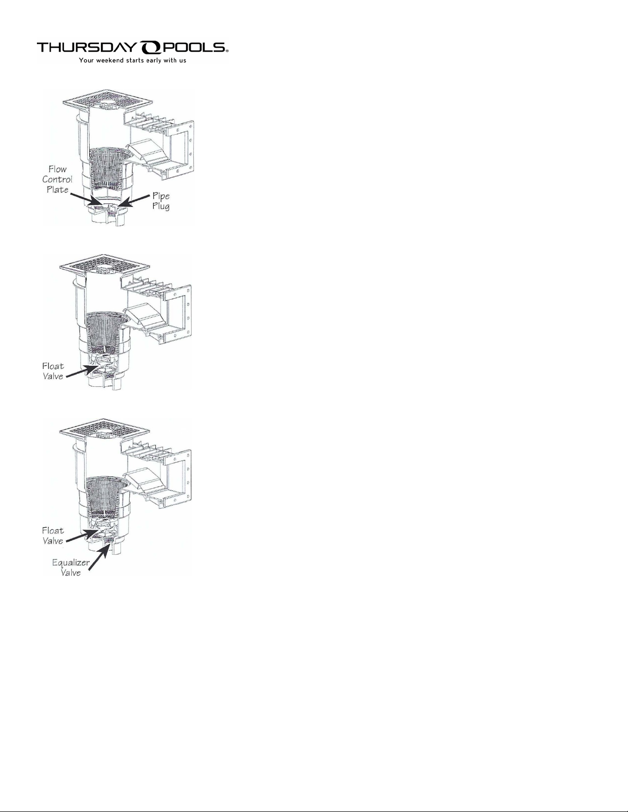
Section 2: Operation of Skimmer
BASIC UNIT
FLOW ADJUSTMENT -To adjust the flow through the skimmer, move the
flow control plate to close the port to the pump to decrease flow, or
move the plate to open the port to the pump to increase flow through
skimmer.
SKIMMER WITH FLOAT VALVE ONLY
FLOAT VALVE OPERATION -The float valve assembly is designed to prevent
any air from entering the pump line when the water level gets too low. If
the water level drops below the skimmer opening, or if water flow is
obstructed, the float inside the valve will automatically close off the
skimmer which will cause the skimmer to draw its water supply of the
main drain line only, thus preventing air lock in the pump. When the
pump is shut off, and the water level is corrected, the flow valve will open
back up automatically, allowing normal skimming operation. To adjust the
flow with the float valve, slide the flow control plate, on the bottom of the
float valve, back and forth until desired flow is achieved.
SKIMMER WITH FLOAT AND EQUALIZER VALVES
EQUALIZER LINER-An equalizer line is used when you have two or more
skimmers plumbed into a common suction line. The operation of the float
valve is the same, but since you have more than one skimmer connected
to the suction line, the equalizer line will help prevent air lock in the
pump.

Lucky 7 Fiberglass Inground Pool Skimmer
Installation and Operating Instructions
5 |Page Lucky 7 Skimmer: Installation And Operation Guide
Section 3: Installation of Optional Equipment
A. Float Valve
1. Press the float valve gasket (Item #6), flat side up, into the groove at the bottom of the skimmer.
2. Place the float valve (Item #5) onto the gasket and press to seal the gasket.
3. To adjust the flow through the simmer, slide the flow control plate, on the bottom of the float valve,
over the hole to reduce the flow, or away from hole to increase flow.
B. Equalizer Valve (for part numbers 540-8400 and 40-8500 only)
1. Place o-ring (Item #13) into the o-ring groove on the bottom side of the equalizer valve.
2. Thread the equalizer valve (Item #12) into the front port of the skimmer.
3. Using the equalizer valve wrench (Item #11), tighten the equalizer valve until valve is seated. The
o-ring is seated.
C. Face Plate Cover
1. Center the face plate cover (Item #7) over the face plate and press into place.
D. Vacuum Plate
1. Remove the lid from the skimmer by unscrewing the two (2) screws and lifting the lid off the
skimmer.
2. If you installed a float valve (Item #5), remove it by removing the basket then removing the float
valve. Also, if you installed an equalizer line or main drain, you must block off that port by turning
the flow control plate (Item #4) over that port. Replace the basket.
3. Place the vacuum plate (Item #16) over the skimmer basket.
4. Fill your vacuum hose with water and slide it onto the vacuum plate.
5. Be sure to replace the lid and secure it with the two (2) screws when possible. Failure to do so could
result in a serious personal injury.
Section 3: Winterizing Skimmer
1. Lower the water level to the base of the skimmer faceplate.
2. Winterize the skimmer lines.
3. Plug both ports of the skimmer line. Waterway plastic NPT Plugs can be used.
4. Water inside the skimmer well can freeze and put pressure on the skimmer walls. Use a Skimmer Plug™,
Gizzmo, or drop a gallon jug 1/3 full of antifreeze into the skimmer to protect it from freeze damage.
NOTE:
Automatic Pool Covers are meant to rest on top of the pool water. The pool water level should be
returned to normal water level.

Lucky 7 Fiberglass Inground Pool Skimmer
Installation and Operating Instructions
6 |Page Lucky 7 Skimmer: Installation And Operation Guide
Section 4: Trouble Shooting
Problem
Cause
Remedy
Pool surface not clean, inadequate
skimming effect.
Skimmer basket full of debris,
improper water flow through the
skimmer, water level incorrect in
pool, poor water circulation
Clean skimmer basket, open flow
control plate, raise or lower water
level, increase surface water
circulation.
Pool surface clean, but bottom is
dirty.
Main drain obstructed, pool water
circulation.
Clear main drain of debris,
increase circulation at bottom of
pool.
Skimmer with Venturi Pump not
getting water.
Valve in off position.
Open valve to ¼ position.
Section 5: Dimensions
Lucky 7 Fiberglass Inground Pool Skimmer
Installation and Operating Instructions
7 |Page Lucky 7 Skimmer: Installation And Operation Guide
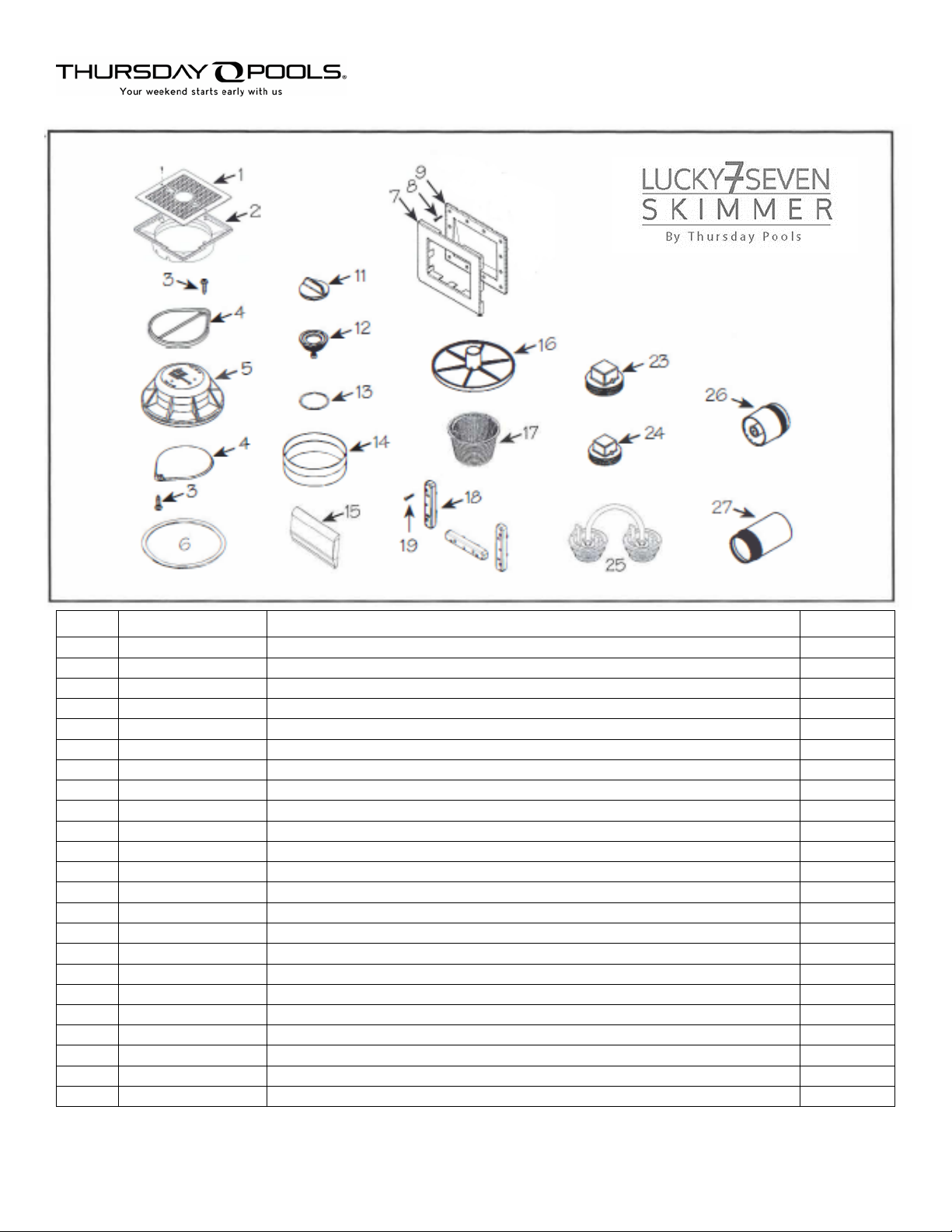
Section 6: Replacement Parts and Accessories
ITEM
PART NUMBER
DESCRIPTION
QUANTITY
1
540-6490TP
Square Lid with Thursday Pools Insert
1
2
519-9510
Square Collar
1
3
819-4350
#8 x 5/8” Phillips Pan Head Screw
1
4
519-6470
Flow Control Plate
1
5
542-6200
Float Valve Assembly (Optional)
1
6
711-6400
Float Valve Gasket (Optional)
1
7
519-9520
Faceplate Cover
1
8
819-6945
#12 x 1 ¼” Phillips Flat Head Screw
12
9
519-9530TP
Face Plate for Fiberglass Pools
1
11
611-4600
Wrench for Equalizer Valve (Optional)
1
12
540-6010
Equalizer Valve Assembly (Optional)
1
13
805-0224
Equalizer Valve O-ring
1
14
519-6560
Collar Extension Ring (Optional)
1
15
550-9550
Weir Door Assembly
1
16
519-6480
Vacuum Plate (Optional)
1
17
542-3240
Basket with Handle
1
18
713-9520
Mounting Flange Spacer
3
19
819-0030
#12 x 1 ¼” Phillips Pan Head Screws
4
23
715-9910
2” NPT Plug
1
24
715-1230
1 ½” NPT Plug
1
25
540-6500
Pressure Test Kit (Optional)
1
26
542-9610
Venturi Skimmer Nozzle Fitting
1
27
519-9650
Sleeve Outlet Port Fitting
1
This manual suits for next models
2
Table of contents
Popular Lighting Equipment manuals by other brands


Feniex
Feniex FUSIONGPL FN-4420 instruction manual

Quoizel
Quoizel DEV8408MBK installation guide

RAB Lighting
RAB Lighting SR2 installation instructions

ADJ
ADJ UB 12H user manual

gamma scientific
gamma scientific SpectralLED RS-7 User's operation manual

Soundoff Signal
Soundoff Signal SINGLE GHOST EGHST2 manual


