TI Navigator User manual

TI-Navigator™
Installation Guide
_____________________________________________
Write the System ID number here.
The number is printed inside the case for the CD.
InstallationGuide.book Page i Wednesday, May 3, 2006 10:19 AM

ii
Important Information
Texas Instruments makes no warranty, either express or implied,
including but not limited to any implied warranties of merchantability
and fitness for a particular purpose, regarding any programs or book
materials and makes such materials available solely on an "as-is" basis. In
no event shall Texas Instruments be liable to anyone for special,
collateral, incidental, or consequential damages in connection with or
arising out of the purchase or use of these materials, and the sole and
exclusive liability of Texas Instruments, regardless of the form of action,
shall not exceed the purchase price of this product. Moreover, Texas
Instruments shall not be liable for any claim of any kind whatsoever
against the use of these materials by any other party.
Copyright © 2006 Texas Instruments Incorporated.
Microsoft®, Windows®, Apple®, Macintosh®, Belkin®, and ZoneAlarm®
are trademarks of their owners.
Regulatory Information
USA FCC Information Concerning Radio Frequency
Interference
Federal Communication Commission Interference
Statement
This equipment has been tested and found to comply with the limits for a
Class B digital device, pursuant to Part 15 of the FCC Rules. These limits
are designed to provide reasonable protection against harmful
interference in a residential installation. This equipment generates, uses
and can radiate radio frequency energy and, if not installed and used in
Product Name: TI-Navigator™
Model Number/Name: Wireless Hub
FCC ID: POTCX6601B
Product Name: AP-201
Model Number/Name: Access Point
FCC ID: POTAP-201
Product Name: AP-201A
Model Number/Name: Access Point
FCC ID: POTAP-201A
InstallationGuide.book Page ii Wednesday, May 3, 2006 10:19 AM

iii
accordance with the instructions, may cause harmful interference to
radio communications. However, there is no guarantee that interference
will not occur in a particular installation. If this equipment does cause
harmful interference to radio or television reception, which can be
determined by turning the equipment off and on, the user is encouraged
to try to correct the interference by one of the following measures:
• Reorient or relocate the receiving antenna.
• Increase the separation between the equipment and receiver.
• Connect the equipment into an outlet on a circuit different from
that to which the receiver is connected.
• Consult the dealer or an experienced radio/TV technician for help.
This device complies with Part 15 of the FCC Rules. Operation is subject to
the following two conditions:
1. This device may not cause harmful interference, and
2. This device must accept any interference received, including
interference that may cause undesired operation.
FCC Caution: Any changes or modifications not expressly approved by
Texas Instruments could void the user's authority to operate this
equipment.
IMPORTANT NOTE:
FCC Radiation Exposure Statement:
This equipment complies with FCC radiation exposure limits set forth for
an uncontrolled environment. This equipment should be installed and
operated with minimum distance 20cm between the radiator and your
body.
This transmitter must not be co-located or operating in conjunction with
any other antenna or transmitter.
IMPORTANT NOTE:
To comply with FCC RF exposure compliance requirements, the antenna
used for this transmitter must be installed to provide a separation
distance of at least 20 cm from all persons and must not be co-located or
operating in conjunction with any other antenna or transmitter.
We declare that CX6601B (FCC ID: POT CX6601B) is limited in CH1~CH11
by specified firmware controlled in U.S.A.
InstallationGuide.book Page iii Wednesday, May 3, 2006 10:19 AM

iv
Europe — EU Declaration of Conformity
Complies with the provisions of the EMC Directive 89/336/EEC according
the following standards as applicable to the particular component:
• EN 55022 Class B, “Limits and methods of measurement of radio
interference characteristics of information technology equipment”
• EN 61000-6-1, “Generic standards — Immunity for residential,
commercial, and light-industrial environments”
• EN 60590 "Safety of Information Technology Equipment”
This device complies with the essential requirements of the R&TTE
Directive 1999/5/EC with essential test suites as per standards:
• ETS EN 300 328-2 Technical requirements for radio equipment.
• ETS EN 301 489-1/-17 General EMC requirements for radio
equipment.
Restrictions
France
Outdoor use limited to 10 mW e.i.r.p. within the band 2454 - 2483.5 MHz.
Italy
If used outside of own premises, general authorization is required.
Canada — Industry Canada (IC)
To prevent radio interference to the licensed service, this device is
intended to be operated indoors and away from windows to provide
maximum shielding. Equipment (or its transmit antenna) that is installed
outdoors is subject to licensing.
Exposure to Radio Frequency Radiation
The radiated output power of the wireless LAN radio cards provided are
certified by the radio card manufacturers to be below the FCC radio
frequency exposure limits. Nevertheless, the equipment should be used
in such a manner that the potential for human contact during normal
operation is minimized.
InstallationGuide.book Page iv Wednesday, May 3, 2006 10:19 AM

Contents
v
Overview ......................................................................................... 1
Hardware type......................................................................... 2
System requirements...................................................................... 2
Minimum system requirements.............................................. 2
Other requirements ................................................................ 3
Recommended items............................................................... 3
Unpacking the boxes...................................................................... 3
Classroom kit ........................................................................... 4
Student kit (up to 16 students) .............................................. 5
Individual kit............................................................................ 5
Assembling and charging the network hubs................................ 6
Removing the network connectors........................................ 7
Checking the LEDs................................................................... 8
Before you begin............................................................................ 8
Installing .................................................................................. 9
Setting up your TI-Navigator™ network the first time ............. 12
Before you begin................................................................... 12
Hardware type and Ethernet adapter type ......................... 13
Connecting the cables to the access point .......................... 13
Starting the wizard ............................................................... 14
Identifying your hardware and selecting a channel ........... 15
Identifying the network connection.................................... 17
Configuring an Ethernet port .............................................. 18
Configuring a USB port......................................................... 20
Setting up your classroom network ..................................... 25
Activating the access point................................................... 26
Activating Type 2 network hubs .......................................... 27
Activating Type 1 network hubs .......................................... 31
Registering your TI-Navigator™ system .............................. 36
Installing the calculator operating system.................................. 39
Connecting the calculators to the hubs ...................................... 41
Installing software Apps on the calculators ............................... 43
Required ................................................................................ 43
Optional................................................................................. 44
Technical information .................................................................. 45
Wireless access point............................................................. 45
Wireless network information ............................................. 45
Access point LEDs .................................................................. 46
Battery information for wireless network hubs.................. 46
Storing the hubs.................................................................... 46
Removing the battery pack .................................................. 46
Hub LEDs................................................................................ 47
Network adapter settings..................................................... 48
InstallationGuide.book Page v Wednesday, May 3, 2006 10:19 AM

vi
Troubleshooting............................................................................ 49
Lost connections .................................................................... 49
Calculator device not responding.........................................49
Messages ................................................................................ 50
Resetting the Type 2 access point ................................................56
Resetting the Type 1 access point ................................................56
Texas Instruments Support and Service ....................................... 55
For general information ....................................................... 55
For TI-Navigator™ technical questions ................................55
For product (hardware) service............................................. 55
Battery Precautions for Calculators ............................................. 56
Battery Precautions for Rechargeable Battery Packs..................57
Storage ................................................................................... 57
Texas Instruments (TI) Warranty Information ............................. 58
Customers in the U.S. and Canada Only............................... 58
Australia & New Zealand Customers only............................58
All Other Customers .............................................................. 59
TI LearningCheck 3.x License Agreement.................................... 72
InstallationGuide.book Page vi Wednesday, May 3, 2006 10:19 AM

1
Overview
The TI-Navigator™ classroom learning system from Texas Instruments can
help you:
• Assess student understanding.
• Verify that students are on task.
• Use classroom results to engage students.
• Get immediate feedback from your students to promote student
achievement.
The system is composed of two parts, hardware and software. The
hardware creates a wireless communications network so that your
computer can communicate with your students’ TI graphing calculators.
The software contains a number of tools to enhance your classroom,
including:
•Activity Center. Lets you run interactive activities with your classes
involving lists, graphs, points, and equations.
•Quick Poll. Lets you send polls to your students, receive the
students’ responses to the polls, and review the poll results with your
students.
•Screen Capture. Lets you capture your students’ calculator screens.
•Class Analysis. Lets you create, distribute, and analyze educational
content.
•LearningCheck™ Creator. Lets you create quizzes and self-
assessment opportunities.
•App and OS Transfer. Lets you transfer TI Graphing Calculator
Operating System (OS) and Applications (Apps) to students’
calculators.
•Transfer tools. Multiple tools that let you send, collect, and delete
data files on your students’ calculators.
You can obtain educational content on the Web at TI’s Activities
Exchange (education.ti.com/activities.) Or, using the tools on the product
CD, you can create your own:
• StudyCard™ stacks
• CellSheet™ application variables
• TI NoteFolio™ Creator text files that you transfer to TI calculators
• TImeSpan™ Creator timelines of chronological events that can be
viewed on a TI calculator
InstallationGuide.book Page 1 Wednesday, May 3, 2006 10:19 AM

2
• Data sets (lists, matrices, and so on)
There are several ways to learn to set up and use the TI-Navigator™
system:
•TheGetting Started poster—a short version of the setup process with
fewer details.
•TheInstallation Guide (this book, provided in both printed and PDF
formats)—complete setup details, troubleshooting, and technical
information.
• Online Help—After you install the TI-Navigator™ software on your
computer, you can access Online Help from the Help menu.
•TheTI-Navigator™ Guidebook, a printed version of the help.
The process of unpacking the equipment, setting up the hardware, and
installing the software will probably require about two hours of your
time.
Hardware type
This Installation Guide is provided primarily for customers who have
purchased the entire TI-Navigator™ system, including the TI-Navigator™
software and the Type 2 hardware.
However, if you already own a TI-Navigator™ 1.0 or 1.1 system, you can
use your current Type 1 hardware with the TI-Navigator™ 2.0 or later
software. Some of the setup procedures are different if you are using
Type 1 hardware; these differences are included in the section “Setting
up your TI-Navigator™ network the first time.”
Note: You cannot mix Type 1 and Type 2 hardware on the same
TI-Navigator™ network.
System requirements
Minimum system requirements
• Windows® XP Professional with Service Pack 1 or Service Pack 2
installed or Windows 2000 with Service Pack 4 installed
• 900 MHz Pentium-compatible CPU (1.2 GHz recommended)
• Video adapter set at 1024 x 768 screen resolution
• 256 MB RAM (512 MB recommended)
• Approximately 350 MB of available hard-disk space (to install
TI Connect™, TI-Navigator™, Network Manager, Class Analysis, and
LearningCheck™ Creator)
• CD-ROM drive
InstallationGuide.book Page 2 Wednesday, May 3, 2006 10:19 AM

3
• Available Ethernet or USB port on the computer
• Internet Explorer version 5.5 or higher (installed and operational)
Other requirements
• The TI-Navigator™ system communicates with specific TI graphing
calculators (TI-73 Explorer, TI-83 Plus, TI-83 Plus Silver Edition, TI-84
Plus, or TI-84 Plus Silver Edition). Your school or your students may
already own these. Calculators are not included with the
TI-Navigator™ system.
• The latest operating system (included on the CD and available at
education.ti.com/latest) must be installed on each graphing
calculator used with the TI-Navigator™ system. For TI-73 Explorer,
use version 1.90 or higher, TI-83 Plus calculators, use OS version 1.19
or higher. For TI-84 Plus calculators, use OS version 2.41 or higher.
Recommended items
• Cradles for the TI-73 Explorer, TI-83 Plus and TI-83 Plus Silver Edition
calculators (sold separately)
• TI ViewScreen™ panel to project the image of your calculator’s
screen using your overhead projector (requires a ViewScreen™
calculator)
• TI Presenter™ video adapter to connect your ViewScreen™
calculator to a TV or projector
• A digital multimedia projector to project the image of your
computer’s screen onto a large screen for classroom viewing
Unpacking the boxes
The TI-Navigator™ product consists of one classroom kit and a
combination of student kits and individual kits, depending on your
specific order. Each kit is packaged separately. If necessary, you can
purchase additional kits to accommodate as many as 40 students.
1. Determine which kits you have received.
2. Unpack the items from the packing materials.
3. Identify each item, and check the items against the following lists to
make sure your order is complete.
InstallationGuide.book Page 3 Wednesday, May 3, 2006 10:19 AM
4
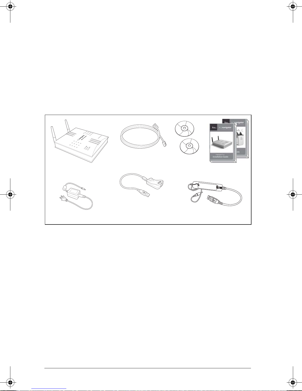
Classroom kit
• 1 access point with AC9926 power adapter
• 1 black Ethernet crossover cable (RJ-45 Category 5)
• 1 Belkin®network adapter (also known as USB-to-Ethernet adapter)
• 2 CDs, one containing system and application software, and one
containing educational activities
• 1 USB Silver Edition cable
•ThisInstallation Guide, the TI-Navigator™ Reference Guide, and
other printed materials
The Standard-A to Mini-B USB cable and the black and gray
TI-GRAPH LINK™ cables and do not work with the TI-Navigator™ system.
The USB-to-Ethernet adapter and USB Silver Edition cable each require a
USB port.
• The USB-to-Ethernet adapter is not needed if the teacher’s computer
already has an available Ethernet port.
• The USB Silver Edition cable is used to connect a calculator to the
teacher’s computer.
Note: Connecting a calculator to the teacher’s computer with the
USB Silver Edition cable adds the calculator to the network without the
need for a network hub. When a teacher uses the calculator to login
using her teacher account, she can send and receive Quick Polls, send files
to the class, or use the Activity Center, all without using the computer.
See the TI-Navigator™ Reference Guide or Help for more information.
Access point
Crossover cable
Network adapter
(USB-to-Ethernet)
AC9926 power adapter USB Silver Edition cable
Two CDs
Classroom kit
Two user guides
InstallationGuide.book Page 4 Wednesday, May 3, 2006 10:19 AM

5
Student kit (up to 16 students)
• 1 charging bay with AC9940 power adapter
• 4 network hubs
• 4 network connectors
• 4 clamps (to attach hubs to student work surfaces)
• 16 data cables (to connect the calculators to the network connectors)
Individual kit
• 1 network hub with AC9926 power adapter
• 1 network connector
•1clamp
• 4 data cables (to connect the calculators to the network connectors)
Student kit
Hub-charging bay
4 network hub
clamps
4 network hubs and
4 network connectors
AC9940 power adapter
(for the charging bay)
16 data cables AC9926 power
adapter (for
individual hub
or access point)
Network hub with
network connector
Network hub
clamp
Individual kit
AC9926 power
adapter
4 data cables
InstallationGuide.book Page 5 Wednesday, May 3, 2006 10:19 AM
6
Assembling and charging the network hubs
The network hubs contain rechargable batteries. Hub batteries are
already charged when shipped, but you should charge them overnight
before using them in your class. When the hubs are fully charged, they
will function all day under continuous use. You should recharge them
each night.
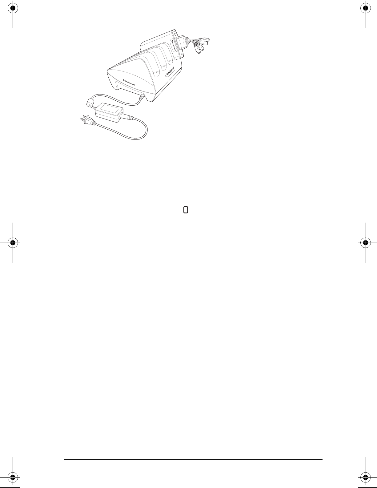
The network charging bay can hold from one to four hubs. After you
place the hubs in the charging bay, they are charged simultaneously until
all are fully charged. If the batteries are fully discharged, it may take up
to 12 hours to fully charge the batteries.
With four network hubs in the charging bay, you should charge them for
12 hours. Typically this is done overnight or over a weekend. When the
hubs are fully charged in the bay, the LED shows solid green.
Note: You cannot damage the batteries by leaving them in the charging
bay beyond the time needed to fully charge them. Also, it is not
necessary to fully discharge the batteries before recharging them.
1. Make sure you have enough (3–4) power outlets for the equipment
you received. If necessary, obtain a plug strip so that you have plenty
of grounded outlets.
2. Insert the small end of the AC9940 power adapter cord into the
charging bay’s power jack.
3. Plug the other end of the adapter into a power outlet.
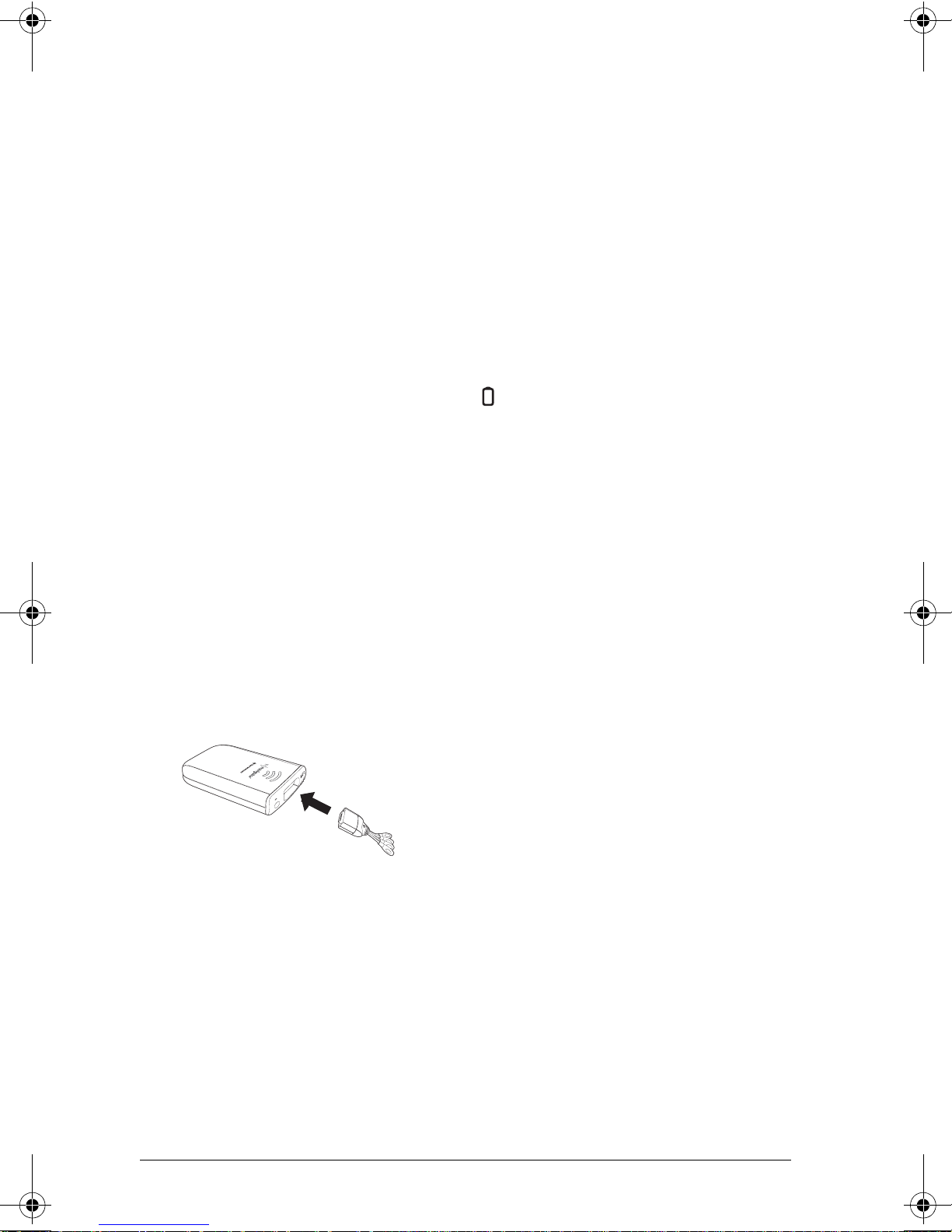
4. Attach a network connector to each hub. Press firmly to make a
good connection.
5. Insert each hub into the charging bay. You can insert them only one
way.
InstallationGuide.book Page 6 Wednesday, May 3, 2006 10:19 AM
7
Note: If you purchased the individual kit and do not have a charging bay,
you can charge a single hub using the AC9926 power adapter instead.
The network connector acts as an on-off switch for the network hub. It
must be connected for the hub to function on the network, but you can
charge a hub with or without a network connector attached. If you
remove a hub from the charging bay with no network connector
attached, the hub’s power-status LED goes off until you attach a
connector.
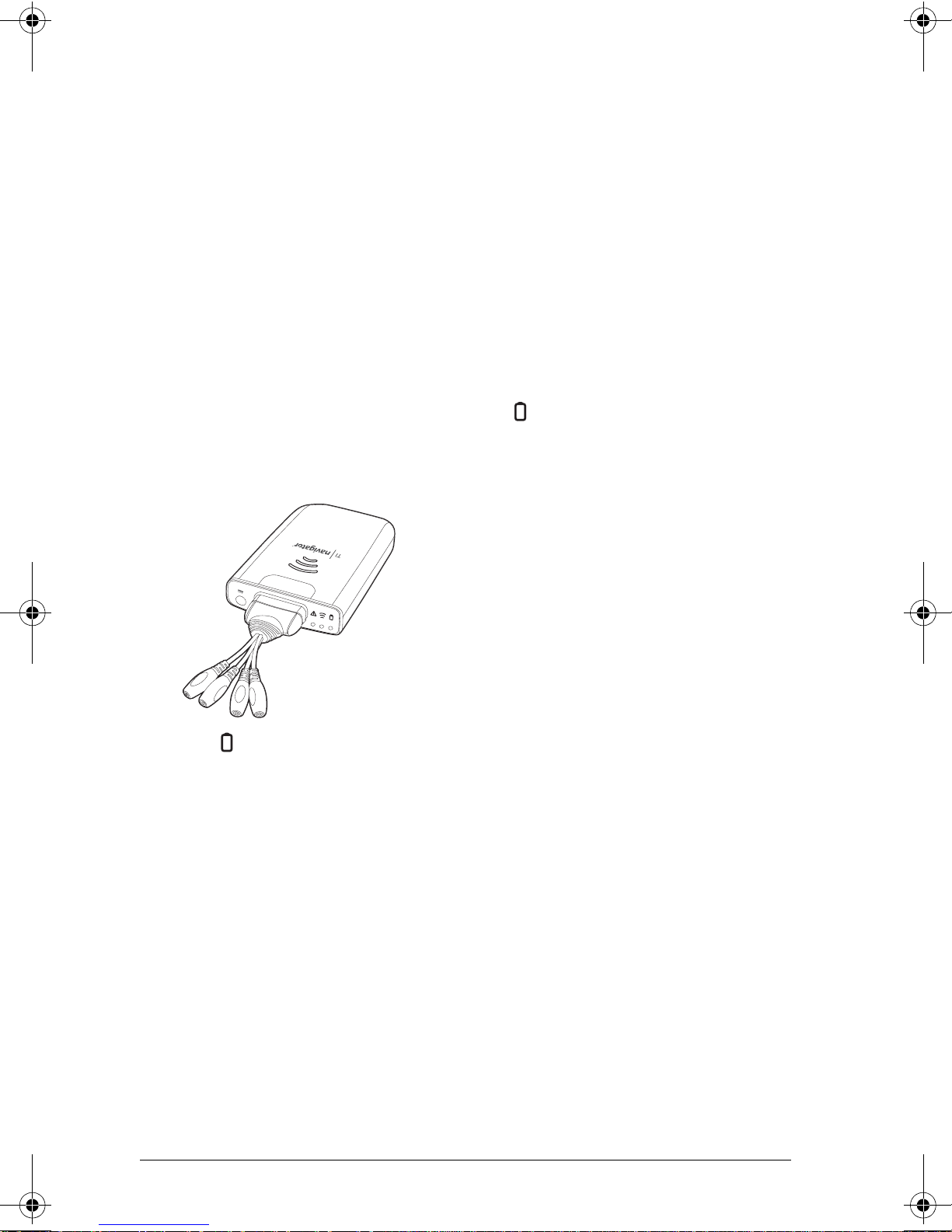
Removing the network connectors
When the hubs are out of the charging bay using battery power but are
not in use, we recommend removing the network connectors from the
hubs to extend battery life.
fTo remove a network connector from a hub, use your thumb
and forefinger to squeeze the two buttons on the sides of the
connector, and then pull it away from the hub.
InstallationGuide.book Page 7 Wednesday, May 3, 2006 10:19 AM
8
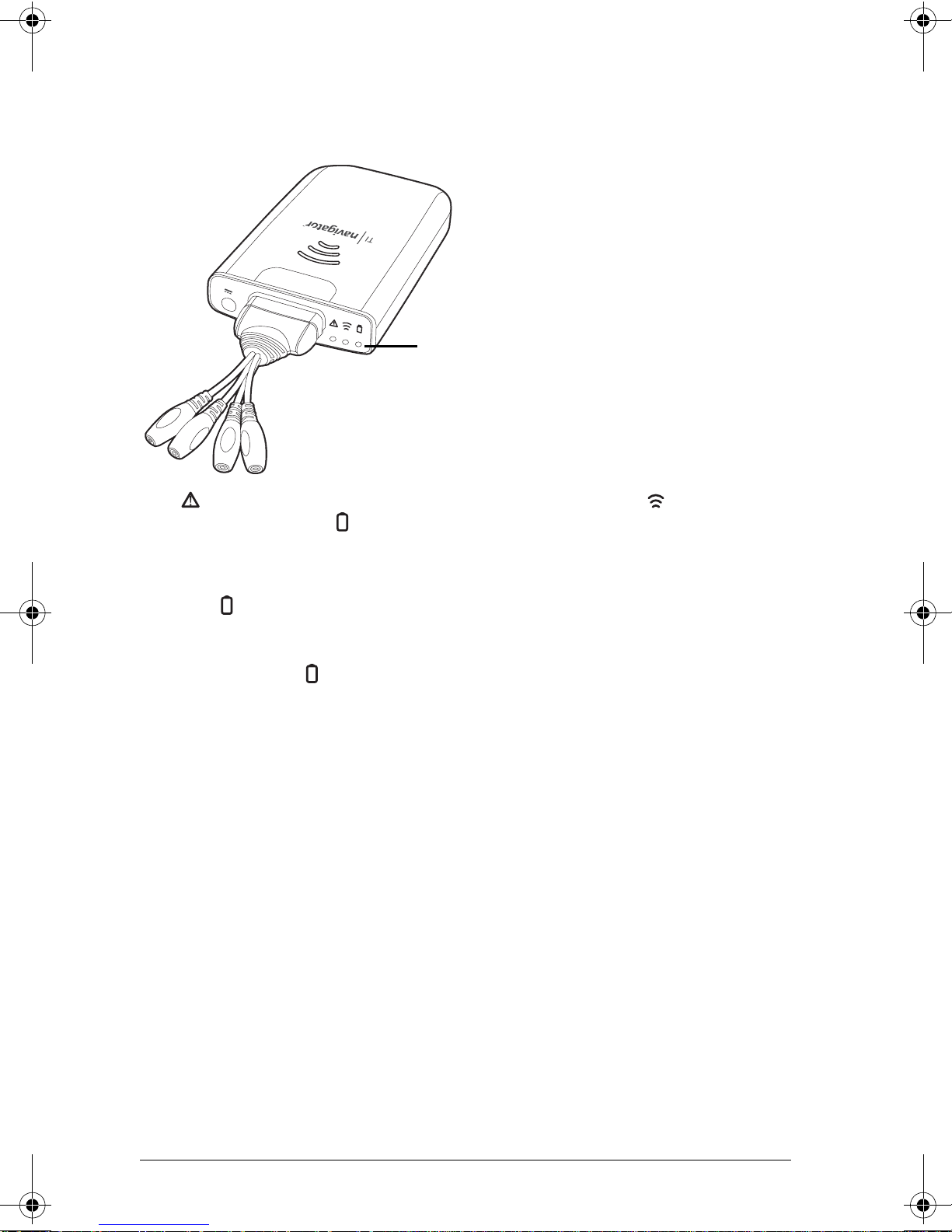
Checking the LEDs
Three LEDs (small lights) at the top of each hub blink or change colors to
indicate various operations or status.
The LED indicates whether the hub is configured. The LED indicates
network activity. The LED indicates battery-charging status.
When the network hubs are still in the charging bay:
• The LED blinking in a green-amber-red sequence means the hubs
are currently recharging.
• A solid green LED means the hub is fully charged.
A complete list of LED operations and status modes is available, along
with complete information about the network hubs’ rechargable
batteries and how to store the hubs. (See “Technical information” on
page 45.)
Before you begin
To install software on your computer, you must have administrator
privileges when you log in to Windows®. If you don’t know whether or
not you have administrator privileges, check with your school’s help desk
or system administrator.
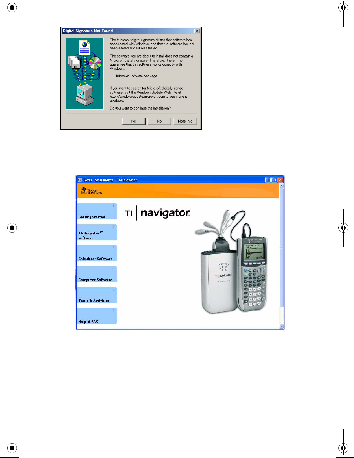
If you see a Digital Signature Not Found message (or a similar message)
while installing, click Yes to continue. The message does not mean there
is a problem.
LEDs
InstallationGuide.book Page 8 Wednesday, May 3, 2006 10:19 AM
9
Installing
1. Insert the TI-Navigator™ CD in your computer’s CD-ROM drive. The
window to the CD should open automatically.
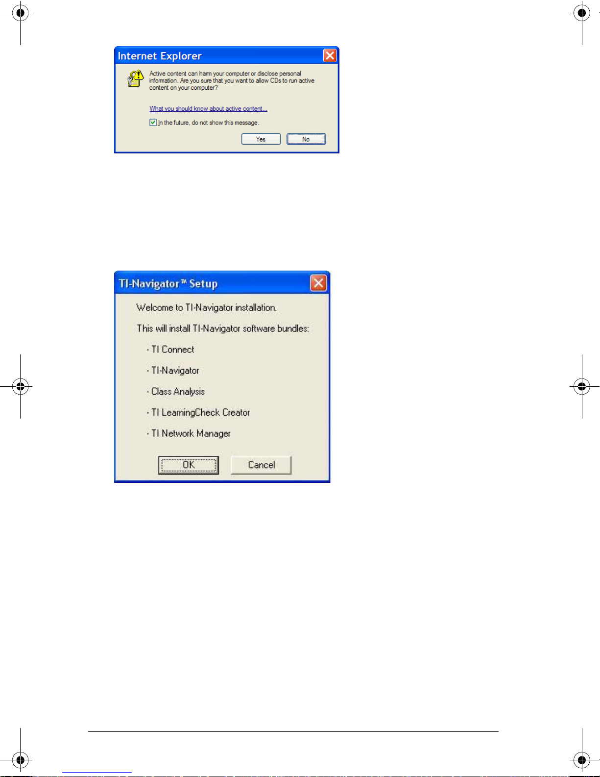
Note: If your computer is running Windows XP Service Pack 2, you
may see the following message. If so, click Yes to continue.
InstallationGuide.book Page 9 Wednesday, May 3, 2006 10:19 AM
10
Note: If the setup program does not run, click Start > Run, and then
type D:\Autorun.exe, where D is your CD-ROM drive, and click OK.
2. Click TI-Navigator Software, and then click Install TI-Navigator™.
The TI-Navigator™ Setup dialog displays.
3. Click OK to continue.
4. Five separate installations will occur:
– TI Connect
– TI-Navigator™ software
– Class Analysis
– LearningCheck™ Creator
– Network Manager software
Note: If version 1.3 or earlier of TI Connect is already installed on
your computer, the installation program will uninstall it, and install
TI Connect 1.6. If earlier versions of other TI-Navigator™ components
are already installed, the installation program will uninstall it and
install the current version.
InstallationGuide.book Page 10 Wednesday, May 3, 2006 10:19 AM

11
When the TI Connect install is complete, you will be prompted to
enter the system ID to install the remaining TI-Navigator™
components.
5. Find the system ID in the case with the CD.
6. When asked, enter the system ID so you can proceed with the
installation.
Note: Enter the system ID exactly as shown. Be careful not to enter a
zero for the letter O or a letter O for a zero.
7. When the installation is complete, the TI-Navigator™ Setup dialog
displays the status of installed components.
You are now ready to set up your network.
Note: If you are using Windows® XP Service Pack 2 and have the built-in
firewall activated, you may have to specify TI-Navigator™ and other
other TI applications as exceptions that you want to allow to
communicate with the TI-Navigator™ network. For more information on
how to allow exceptions for specific applications using the built-in
firewall, see your Windows Help.
(sample)
TI-Navigator™ System ID
48z6-co2j-cyms-qol2x
InstallationGuide.book Page 11 Wednesday, May 3, 2006 10:19 AM
12
Setting up your TI-Navigator™ network the first
time
A Network Setup wizard helps you connect the TI-Navigator™ parts in
the correct order, activate the access point and hubs for wireless
communication, and register the TI-Navigator™ product.
Before you begin
1. Make sure you have installed the TI-Navigator™ software on your
computer.
2. Make sure the access point is not yet plugged in to a power outlet. If
you are using the USB-to-Ethernet adapter, make sure it is not yet
connected to the computer’s USB port.
3. Make sure each hub is fully charged ( LED is solid green).
4. Remove the hubs from the charging bay. Each hub must have a
network connector attached.
The LED changes from solid green to blinking green when you
remove a hub from the charging bay.
5. Have a ball-point pen or paper clip handy; you’ll need it to reset the
hubs.
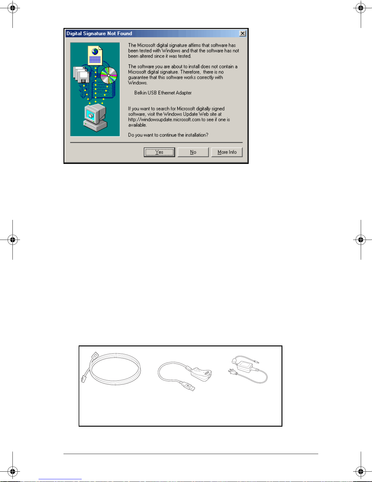
Note: If you see a Digital Signature Not Found message while setting up
your network, click Yes to continue. The message does not mean there is
a problem.
InstallationGuide.book Page 12 Wednesday, May 3, 2006 10:19 AM
13
Hardware type and Ethernet adapter type
If you already own a TI-Navigator™ 1.0 or 1.1 system, you can use your
current Type 1 hardware with the TI-Navigator™ 2.0 or later software. If
you purchased the complete TI-Navigator™ 2.0 or later system, you will
set up the Type 2 hardware with the TI-Navigator™ 2.0 or later
software. Some of the setup procedures are different depending on
which hardware you are using.
Another consideration is the network port on your computer.
• If you have an available Ethernet port on your computer, you should
use it to connect to the TI-Navigator™ access point.
• If you do not have an available Ethernet port on your computer, you
must use the USB-to-Ethernet adapter to connect to the
TI-Navigator™ access point.
Connecting the cables to the access point
1. Identify the cables.
2. Remove the side plate from the access point.
AC9926 Power
adapter
Network adapter
(USB-to-Ethernet; not
needed if an Ethernet
port is available)
Ethernet crossover
cable
InstallationGuide.book Page 13 Wednesday, May 3, 2006 10:19 AM

14
3. Connect the AC9926 power adapter to the power jack on the access
point, but don’t plug the power adapter into a power outlet
yet.
4. Connect the Ethernet crossover cable to the access point.
If your classroom computer has an available Ethernet port, you will use it
to connect to the access point. If not, you will use the network adapter
(USB-to-Ethernet).
Starting the wizard
A First Time Setup screen opens automatically when you complete the
installation of the TI-Navigator™ software. You are immediately
prompted to run the network setup wizard.
Note: If you want to run the Setup Wizard later, you will click Start >
Programs > TI Tools > TI Network Manager. When Network Manager
opens, or click Actions > Setup Wizard from the TI-Navigator™ menu.
Ethernet
crossover cable
plugs in here
AC9926 power
adapter plugs in
here
InstallationGuide.book Page 14 Wednesday, May 3, 2006 10:19 AM
Other manuals for Navigator
2
Table of contents
Other TI GPS manuals


