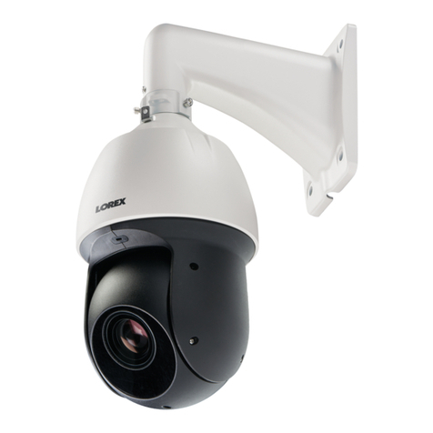
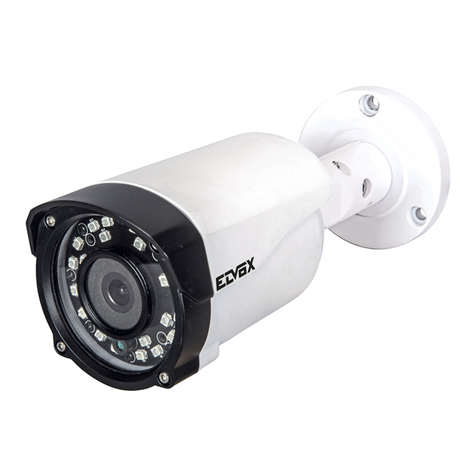
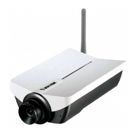
Tiandy S3E 1.3M Series User manual

1
Network Camera
User Manual

2
Contents
Chapter 1 Warning ..........................................................................................................................3
Chapter 2 Product Overview ..........................................................................................................5
Chapter 3 Function Overview.........................................................................................................8
3.1 Parameter of IP Camera ....................................................................................................8
3.2 Hardware Interface .........................................................................................................10
Charpter 4 Common function.......................................................................................................12
4.1 Product upgrade..............................................................................................................12
Charpter 5 Installation Instruction ..............................................................................................13
5.1 Installation Preparation..................................................................................................13
5.2:Installation Instruction:..................................................................................................14
Chapter 6 WEB Instruction...........................................................................................................17
6.1 System Requirement .......................................................................................................17
6.2 Built-in Web Instruction .................................................................................................17
6.3 Log in................................................................................................................................18
6.4 Preview.............................................................................................................................18
6.5 Playback ...........................................................................................................................20
Chapter 7 Configuration................................................................................................................22
7.1 Audio Video Set................................................................................................................22
7.2 Camera Set .......................................................................................................................24
7.3 VCA ...................................................................................................................................26
7.4 OSD ...................................................................................................................................28
7.5 Storage Management.......................................................................................................29
7.6 Network Management.....................................................................................................31
7.7 User management ...........................................................................................................33
7.8 Alarm Management.........................................................................................................34
7.9 PTZ Management and Control........................................................................................36
7.10 Advance..........................................................................................................................36
Charpter 8 Simple Fault Maintenance..........................................................................................38
8.1 System Failure..................................................................................................................38
8.2 Network Failure...............................................................................................................38
8.3 Operation Failure.............................................................................................................40
8.4 Control Failure.................................................................................................................41
8.5 Video Failure....................................................................................................................41
8.6 Audio Failure....................................................................................................................41
8.7 Alarm Failure ...................................................................................................................42
Charpter 9 After-sales Service......................................................................................................43
Charpter 10 Harmful Elements ....................................................................................................44

3
Chapter 1 Warning
TO REDUCE THE RISK OF FIRE OR ELECTRIC SHOCK, DO NOT EXPOSE
THIS PRODUCT TO RAIN OR MOISTURE. DO NOT INSERT ANY METALLIC
OBJECT THROUGH THE VENTILATION GRILLS OR OTHER OPENNINGS
ON THE EQUIPMENT.
Apparatus shall not be exposed to dripping or splashing and that no objects
filled with liquids, such as vases, shall be placed on the apparatus.
CAUTION
EXPLANATION OF GRAPHICAL SYMBOLS
The lightning flash with arrowhead symbol, within an equilateral triangle, is intended to alert the
user to the presence of “dangerous voltage” within the product’s enclosure that may be of
sufficient magnitude to constitute a risk of electric shock to persons.
The exclamation point within an equilateral triangle is intended to alert the user to the presence
of important operating and maintenance (servicing) instructions in the literature
accompanying the product.
Battery
Batteries(battery pack or batteries installed) shall not be exposed to excessive
heat such as sunshine, fire or the like.
Disconnection Device
Disconnect the main plug from the apparatus, if it’s defected. And please call a repair man in your
location.
When used outside of the U.S., it may be used HAR code with fittings of
an approved agency is employed.
CAUTION
These servicing instructions are for use by qualified service personnel only.
To reduce the risk of electric shock do not perform any servicing other than
that contained in the operating instructions unless you are qualified to do so.
The BNC Out terminal of the product is provided for easier installation, and is not recommended

4
for monitoring purposes.
If you keep the BNC cable connected, a risk of lightening may cause damage or malfunction to the
product.
Please use the input power with just one camera and other devices must not be connected.
Please read the following recommend safety precautions carefully.
Do not place this apparatus on an uneven surface.
Do not install on a surface where it is exposed to direct sunlight, near
heating equipment or heavy cold area.
Do not place this apparatus near conductive material.
Do not attempt to service this apparatus yourself.
Do not place a glass of water on the product.
Do not install near any magnetic sources.
Do not block any ventilation openings.
Do not place heavy items on the product.
User’s Manual is a guidance book for how to use the products.
The meaning of the symbols are shown below.
Reference : In case of providing information for helping of product’s usages
Notice : If there’s any possibility to occur any damages for the goods and human caused by
not following the instruction
Please read this manual for the safety before using of goods and keep it in the safe place.

5
Chapter 2 Product Overview
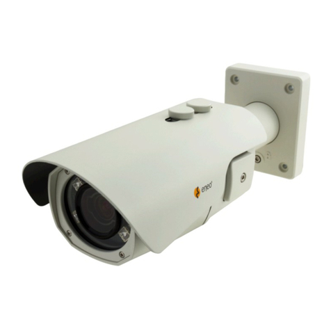
IP Box Camera
Size of IP box camera
IP IR Bullet Camera ( fixed lens)
Size of IP IR bullet camera (fixed lens)
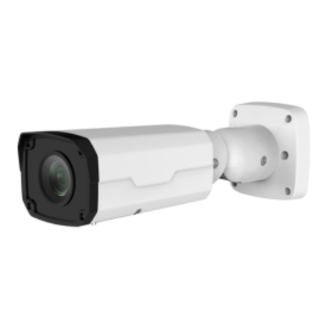
IP IR Bullet Camera ( varifocal lens)

6
Size of IP IR bullet camera (varifocal lens)
IP IR Dome Camera (fixed lens)
Size of IP IR Dome Camera (fixed lens)
IP IR Dome Camera (varifocal lens)

7
Size of IP IR Dome Camera ( varifocal lens)

8
Chapter 3 Function Overview
3.1 Parameter of IP Camera
3.1.1 IP Box Camera
S3E Series 1.3M
S3E Series 2M
core
processor
ARM9 Architecture processor
operating
system
Embedded LINUX
Video
Compression
Support H.264 baseline,main profile, M-JPEG
Audio
Compression
G.711/G.726/ADPCM/AAC
Image sensor
1/3 Inch CMOS
1/2.8 Inch CMOS
Image
resolution
1280x960
1920x1080
Framerate
960P@30 F/S
1080P@30 F/S
Lens interface
type
C/CS,DC
WDR
100dB
Image
processing
Support NIR,3D noise reduction,de-interlace,image enhancement, edge enhancement,
backlight compensation, gamma adjustment
Electronic
Shutter
Support auto/manual,1s~1/10000s
Day/Night
ICR
code rate
Video Compression code rate:32K~16M bps,Audio Compression code rate:8k,32k,48K
interface
Two-way audio,alarm input,TF card,analog video
option
POE,analog video output,alarm output,RS485
Network Port
10M/100M Ethernet interface
Network
protocol
TCP/UDP/HTTP/MULTICAST/UPnP/NTP/RTSP/Onvif
IVA
support tripwire, Perimeter
Ingress
Protection
TVS 4000V lightning protection
power
Not include,suggest DC12V ±10%
3.1.2 IP IR Bullet Camera:
S3E Series 1 M
S3E Series 1.3 M
S3E Series 2M

9
core
processor
ARM9 Architecture processor
operating
system
Embedded LINUX
Video
Compression
Support H.264 baseline,main profile, M-JPEG
Audio
Compression
G.711/G.726/ADPCM/AAC
Image sensor
1/4 Inch CMOS
1/3 Inch CMOS
1/2.8 Inch CMOS
Image
resolution
1280x720
1280x960
1920x1080
Framerate
720P@30 F/S
960P@30 F/S
1080P@30 F/S
Lens
interface type
fixed lens/varifocal lens for option
WDR
100dB
100dB
100dB
Image
processing
Support NIR,3D noise reduction,de-interlace,image enhancement, edge enhancement,
backlight compensation, gamma adjustment
Electronic
Shutter
Support auto/manual,1s~1/10000s
IR Distance
30-50m
Day/Night
ICR
code rate
Video Compression code rate:32K~16M bps,Audio Compression code rate:8k,32k,48K
interface
Two-way audio,alarm input,USB
option
POE,analog video output,alarm output,RS485
Network Port
10M/100M Ethernet interface
Network
protocol
TCP/UDP/HTTP/MULTICAST/UPnP/NTP/RTSP/Onvif
IVA
support tripwire, Perimeter
Ingress
Protection
IP66, TVS 4000V lightning protection
power
Not include,suggest DC12V ±10%
3.1.3 IP IR Dome Camera:
S3E Series 1 M
S3E Series 1.3 M
S3E Series 2 M
core
processor
ARM9 Architecture processor
operating
system
Embedded LINUX
Video
Compression
Support H.264 baseline,main profile, M-JPEG
Audio
Compression
G.711/G.726/ADPCM/AAC

10
Image sensor
1/4 Inch CMOS
1/3 Inch CMOS
1/2.8 Inch CMOS
Image
resolution
1280x720
1280x960
1920x1080
Framerate
720P@30 F/S
960P@30 F/S
1080P@30 F/S
Lens interface
type
fixed lens/varifocal lens for option
WDR
100dB
100dB
100dB
Image
processing
Support NIR,3D noise reduction,de-interlace,image enhancement, edge enhancement,
backlight compensation, gamma adjustment
Electronic
Shutter
Support auto/manual,1s~1/10000s
IR Distance
20-30m
Day/Night
ICR
code rate
Video Compression code rate:32K~16M bps,Audio Compression code rate:8k,32k,48K
interface
Two-way audio, alarm input, alarm output, camera recording for option
option
POE,analog video output,alarm output,RS485
Network Port
10M/100M Ethernet interface
Network
protocol
TCP/UDP/HTTP/MULTICAST/UPnP/NTP/RTSP/Onvif
Ingress
Protection
All aluminum, TVS 4000V lightning protection
IVA
support tripwire, Perimeter
power
Not include,suggest DC12V ±10%
Please take the actual device as the standard
3.2 Hardware Interface

11
3.2.1 Interface Introduction
type
function
name
description
System
interface
power
DC12V
DC12V±10%
Ethernet
interface
ETHERNE
T
10M/100M,RJ45
Audio/video
interface
Video output
VIDEO
OUT
BNC(Q9)interface, 75Ωp-p analog video signal output
(only box camera)
Audio input
IN
linear signal input,G is common port,input voltage ≤1V;
(for option)
Audio output
OUT
linear signal output,G is common port, should with active
speaker(for option)
extend interface
(option)
Alarm
interface
ALARM
1-ch input&1-ch output,
IN&G alarm input interface,G is common port
OUT,COM are alarm output interface ;COM is ground
terminal(for option)
Control
interface
RS-485
A:485(+), B:485(-);(only box camera)
Recording
interface
support
TF CARD
Micro SD max support 32G
USB
Support 32G(for option)
Notes: Only Vari-focal Camera owns all these ports; Fixed len camera only has ports for Ethernet
and power supply.

12
Charpter 4 Common function
4.1 Product upgrade
How to upgrade the version of product
step
description
1
Connect computer and network video to the same network, and modify the ip
address to the same network segment.
2
Input device address and login
3
Select kernel file(*.bin) and start upgrade, program will restart automatically
4
Select web file(*.box) and start upgrade, program will restart automatically
5
Login web-advanced option and check if upgrade is successfully

13
Charpter 5 Installation Instruction
5.1 Installation Preparation
1. Preparation
All electrical work must comply with the latest electrical codes, fire regulations and relevant
laws and regulations;According to the packing list check if all accessories are in the package and
determine the location of the high speed dome camera and installation applications are consistent
with the requirements; if not match, please contact your dealer. Please follow the work
environment requires the use of the product. Depending on the circumstances actually required to
prepare your own tools.
2. Necessary Tools:
Fig 4.1.1Tools
3. Check the installation location space and intensity
Please make sure the location has sufficient space and intensity to install. The ceiling, wall
or bracket must be able to bear 4 times the weight of the IP camera itself.
4. Please save all packaging material
Please well keep the original packing materials, in order to send back if any problem.
★Note: Non-original packing material may result in accidental damage in transit.

14
5.2:Installation Instruction:
5.2.1 HD IP Box Camera:
Taking wall mount as example
HD IP Box Camera Installation
Steps:
1, Mark the installation holes in the wall by ink pen
2, Drill holes in marked points.
3, Plug the expansion bolts into the holes.
4 Screw the bracket fastened to the wall.
5, Fix two nut screws aligned camera position and rotate tight. Adjust bracket gimbals to
appropriate location.
5.2.2 HD IP IR Bullet Camera (Fixed&Varifocal):
Taking wall mount as example

15
HD IP IR Bullet Camera Installation
Steps:
1, Mark the installation holes in the wall by ink pen
2, Drill holes in marked points.
3, Plug the expansion bolts into the holes.
4 Screw the bracket fastened to the wall.
5, Fix two nut screws aligned camera position and rotate tight. Adjust bracket gimbals to
appropriate location.
5.2.3 HD IR Dome Camera (Fixed):
Taking ceiling mount as example
HD IP IR Dome Camera(Fixed) Installation
Steps:

16
1, Take out camera and unscrew the three screws on the housing, remove the bottom chassis
2, Mark the installation holes in the wall by ink pen
3, Drill holes in marked points.
4, Plug the expansion bolts into the holes.
5, Fix the three φ5 screws on dome camera and fasten on the wall. Assemble the components
removed from the first step. Adjust the lens direction to the proper position and tighten the three
screws.
5.2.4 HD IR Dome Camera (Varifocal):
Taking ceiling mount as example
HD IP IR Dome Camera(Varifocal) Installation
Steps:
1, Paste positioning on the wall
2, Punch holes on marked points and plug in expansion bolts.
3, Loose the three screws and remove dome cover, fasten the dome base on ceiling.
4, Adjust camera lens to the proper angle, and tighten the screws
5, Aligned cover with mount position, adjust black hood position and tighten the screws.

17
Chapter 6 WEB Instruction
6.1 System Requirement
IP camera web settings support WindowsXP,Win7 and Win8 system, please make sure right
installation and setup of following items:
(1)Display resolution: 1400 * 900 or higher, color: High Color (32-bit).
(2)Please make sure the Windows system install the necessary character style.
6.2 Built-in Web Instruction
When using the network video products for the first time, an ActiveX control is needed.
(1)Login IP address and enter to ActiveX download interface
(2)Download ActiveX and click 【Run】to install;
(3)Shot down the WEB before installation and click【Next】.
(4)Input IP address of camera and allow to add plug-in after installation success.
(5)When you success to load plug-in, it shows page as below. Then please enter ID, password.

18
Note: Please ensure IE version above 6.0. And do not use any other browser except Firefox and
Chrome.
6.3 Log in
(1)Default user name is “Admin”
(2)Default password “1111”
(3)If you want to change port number, please enter right port number after IE shows port
number after you success to log in.
6.4 Preview

19
6.4.1 Preview page
Descriptions of live view parameters and toolbar
Icon
Description
Icon
Description
Major stream
Manual recording on / off,
and default storage path is
D\NetVideoBrowser\
Minor stream
Manually capture, and
default storage path is
D\NetVideoBrowser\
Third stream
Intercom on/off
Screen lock
Full screen
Screen adapt to current
resolution
Audio on, volume adjustment
and mute
Note: When stream type is【Pure Video】,audio preview is invalid.
6.4.2Video parameter
(1)<Default> to resume the default settings.
(2)According to network situation you can choose preview
mode from <Low bandwidth>, <Low latency> to <High
quality>, <High fluency>

20
6.4.3 PTZ control
(1)Select rotation direction of speed dome,
enable auto scan.
(2)<Zoom>Zoom in /Zoom out
(3)<Focus> Manual Focus.
(4)<Iris>Manually adjust iris.
(5) set PTZ speed
(6) Wipper
(7) Preserved for future functions
6.4.4 Preset position
Search the target preset number
<Set> Setup preset position
<Call>Call the preset position
6.5 Playback
This manual suits for next models
3
Table of contents
Other Tiandy Security Camera manuals
