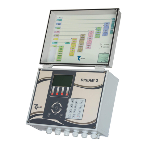
Tidomat smartONE 2 Guide


TIDOMAT smartONE 2 – Start Guide
2 © 2008 Tidomat AB Version 1.0
© 2008 Tidomat AB. All rights reserved.
No part of this publication may be reproduced, stored in
a retrieval system, or transmitted, in any form by any
means, electronic, mechanical, recording or otherwise,
without the prior written permission of Tidomat AB.
The content of this publication is furnished for
informational use only. Data subject to change without
notice and should not be construed as a commitment by
Tidomat AB.
TIDOMAT, the TIDOMAT logo, smartONE and the
smartONE logo are registered trademarks of Tidomat AB.
All other trademarks are the property of their respective
owners.
www.tidomat.se
info@tidomat.se
dok.no. 01080011-0848
© 2008 Tidomat AB
CONTENT
General information....................................................................................... 3
Overview of smartONE .................................................................................. 3
Commissioning .............................................................................................. 4
Login to the System ........................................................................................ 4
Changing the Password.................................................................................. 4
Configuring the Access Points......................................................................... 4
Creating a new Cardholder............................................................................ 5
Connect new Card/tag................................................................................... 5
Instructions for connecting the Central Unit..................................................... 6
Overview of the connections for the Central Unit............................................. 8

TIDOMAT smartONE 2 – Start Guide
Version 1.0 © 2008 Tidomat AB 3
General information
TIDOMAT smartONE is commissioned when all
units are situated at the correct location. The
contact between the computer and the Central Unit
is to be established. These Access Points are to be
configured in the system
.
To see the Instructions for connecting the Central
Unit, please go to page 6.
Overview of smartONE
Requirements for new installation of smartONE:
•A computer with a
TCP/IP
connection.
A Local Area Network,
LAN
connected to at least
one computer.
•One network output,
RJ45
for each Central Unit.
•One
IP-address
for each Central Unit.
•One
DHCP-server
or information regarding the
Subnet mask
,
Broadcast
and
Standard-gateway
of
the network.

TIDOMAT smartONE 2 – Start Guide
4 © 2008 Tidomat AB Version 1.0
Commissioning
One or several Door Controllers are connected
to the Central Unit, and thereafter configured in
the user interface. The Central Unit is to be
connected to the network .The current
consumption should be 24 VDC or 12 VDC
regulated voltage. In the following example, the
Door Controller is connected to Connector P1.
Further Door Controllers can be commissioned
once the system is up and running.
The label underneath the chassis of the Central
Unit displays an Internet address:
Connect to the Central Unit by opening the web
browser and state the Internet address in the
field:
Login to the System
On the initiating page, the following window
appears:
1. Type User:
system
.
2. Login with the Password:
smart
.
Changing the Password
Change the default password to a personal one. It is
recommended to have a password of at least six
characters of which at least two are numbers.
1. Click on User>Password.
2. Type the Password you used to login.
3. Type your New Password.
4. Confirm you New Password and click on Save.
Configuring the Access Points
In order to configure the Access Points, please go to
Access Points>New. The following window appears:
State the connector for P1-P8 or P1-P16, depending on
the model of the Central Unit.
1. Give the Access Point a name.
2. Select the Type of Card Reader.
3. Click on Save.
Further settings and functions can be selected later.
Instructions and explanations are enclosed in the help
files of the system as well as in
Access Points,
Appendix I
in the
TIDOMAT smartONE User Manual
.

TIDOMAT smartONE 2 – Start Guide
Version 1.0 © 2008 Tidomat AB 5
Creating a new Cardholder
The Cardholders are administrated in the
Admin-layer. Open smartONE via the web
browser, or if the user is logged in to the
System-layer, click on Logout in the right hand
corner. Enter admin for the user and admin for
the password to login.
In the menu, go to Cardholder>New. The
following window appears:
1. State the Cardholder’s First name.
2. State the Cardholder’s Surname.
Connect new Card/tag
Via the USB Reader:
1. By the header New Card/tag, place the
curso r in the field on the right.
2. Hold the Card/tag in proximity to the USB-
reader. The Card data will appear in the
field.
3. The field to the left is for your personal
choice of the Card identification.
4. Click on Save.
Via the Card Reader:
1. Hold the Card/tag in proximity to the Card Reader.
2. When the Card Reader has registered the
Card/tag, a red light will flash. Return to the user
interface.
3. Click on the button List new Card/tag .
The list displays the ten latest unknown Cards/tags registered,
the Access Point to which the Card Reader is connected as well
as at what time the cards/tags where registered.
4. Click on the orange button, Update card/tag .
5. Wait for the data of the Card/tag to be displayed in
the field.
6. Select the Card/tag.
7. The field to the right behind the header New
Card/tag displays the Card/tag data. The field to
the left of the Card/tag data is for your personal
choice of the Card identification. You can use
letters and/or digits. If you do not wish to use the
Card identification, please leave the field blank.
8. Click on Save.
The security system smartONE is ready to be used.
Information on how to use functions such as Schedules,
Time Channels and Triggers is enclosed in the
TIDOMAT smartONE User Manual
and the help files.
In order to close the system, please click on
Logout
in
the right hand corner, or close the web browser.

TIDOMAT smartONE 2 – Start Guide
6 © 2008 Tidomat AB Version 1.0
Instructions for connecting the Central Unit
The Exit button should be closed circuit (NO).
The current consumption should be 24 VDC or 12
VDC regulated voltage. The Electric Door Strike is
supplied with the same voltage as the Central
Unit, 24 VDC or 12 VDC. The current consumption of
the Electric Door Strike must not exceed 500 mA.
To see the Overview of the Connections for the Central
Unit, please go to page 8.
The Central Unit SO-3008
Terminal
Pin
Description
P1 - P8
1 0 VDC Connects to the Door Controller
(1PWR)
2 +12/+24 VDC Connects to the Door Controller
(2PWR)
3 +COM Connects to the Door Controller
(+COM)
4 -COM Connects to the Door Controller
(-COM)
0V
Regulated voltage IN 0 VDC
+12V
+24V
Regulated voltage IN +12 VDC alt. 24 VDC
10/100
BaseT
Network Connection, Ethernet 10/100 Mbit/s (Autonegotiation)
COM GSM-modem, special cable for smartONE
The Expansion Card
Terminal
Pin
Description
P9 – P16
1 0 VDC Connects to the Door Controller
(1PWR)
2 +12/+24 VDC Connects to the Door Controller
(2PWR)
3 +COM Connects to the Door Controller
(+COM)
4 -COM Connects to the Door Controller
(-COM)
0V
Regulated voltage IN 0 VDC
+12V
+24V
Regulated voltage IN +12 VDC alt. 24 VDC

TIDOMAT smartONE 2 – Start Guide
Version 1.0 © 2008 Tidomat AB 7
The Door Controller SO-3301
Pin
Description
EXT IN1 External Input
EXT IN1
EXIT1 Exit Button (NO)
EXIT2
DOOR+ Electric Door Strike +
DOOR- Electric Door Strike -
AUX1 Relay (NO eller NC)
AUX2
DATA Communication Connects to the Card Reader
(DATA)
CLK Communication Connects to the Card Reader
(CLK)
+5V Voltage UT Connects to the Card Reader
(+5V)
0V Voltage UT Connects to the Card Reader
(0V)
-COM Communication Connects to the Central Unit
(4)
+COM Communication Connects to the Central Unit
(3)
2PWR Voltage IN Connects to the Central Unit
(2)
1PWR Voltage IN Connects to the Central Unit
(1)
The Card Reader
Pin
Description
0 VDC Voltage IN Connects to the Door Controller
(0V)
+5 VDC Voltage IN Connects to the Door Controller
(+5V)
Clk Communication Connects to the Door Controller
(CLK)
Data Communication Connects to the Door Controller
(DATA)

Overview of the connections for the Central Unit
© 2008 Tidomat AB
All rights reserved. Data subject to change
without notice. 01080011-0848
www.smartone.info
Table of contents

