Bame DELMA SIRIO 4-24V User manual

SIRIO 4 - 24V
C O N T R O L
BO A R D FO R
BA R R IER S
U SER
M A N U A L

SIRIO 4 - 24V
SUMMARY
1. ELECTRIC CONNECTIONS
2. BASIC SETTINGS
3. WORKING TIME ( AUTOMATIC )
4. WORKING TIME ( PROFESSIONAL )
5. REMOTE CONTROLS
6. TRIMMERS AN A JUSTMENTS
7. IP-SWITCHES
8. EXTERNAL BOAR S
9. LE S
When installing the device, insert a switch with a contact opening of at least 3mm
which ensures the equipment omni-polar disconnection from the power supply.
!!!Please read carefully this manual before proceeding with the installation of the
device!!!
1
TRANSFORMER
230V
230V
\
\
SWITCH
T

• ouble limit switch input open close
• Motor force (speed) adjustable from 50-100%.using a trimmer.
• Softstart (slow motor start)
• 1 to 60” stand-by time adjustment via trimmer.
• 0.1 to 3.0” obstacle detection triggering time adjustment via trimmer.
• Initial settings using dip-switches
• Signalling LE s
• Expansion for arm light and traffic light
• Built in battery charger with solar panel management
• Box predisposed for optional 12V 1.2Ah battery for emergency manoeuvres
(max connectable battery 7Ah)
• Built-in 433MHz rolling-code receiver with 200 memorisable codes
• Built to European reference irective Standards (R&TTE 99/05/CE)
Transformer power supply: 230VAC
Control unit power: 20VAC
Motor output: 24V C
Max current peak of motor: 10 Amperes
Accessories power: 24 V C - 250 mA protected by fuse
Environmental operating temperature : -20°C / + 55°C
Programming parameters: memorised in EEPROM
TECHNICAL SPECIFICATIONS
2

1 2 3 4 5 6 7 8 9 10 11 12 13 14 15 16 17 18 19 20 21 22 23 24 25 26 27
MOTOR
BLU - RE
1 2 3 4
1 2 3 4
1 2 3 4
1 2 3 4
LIMIT SWITCH
POWER
SUPPLY
24VCC
1. ELECTRIC CONNECTIONS
28
29
3

!!!ATTENZIONE!!!
IF NOT USE INSERT A JUMPER BEETWEEN:
. STOP : 21 – 22
. SAFETY E GE : 19 – 22
. PHOTOCELLS : 20 - 22
28-29 POWER SUPPLY POWER SUPPLY 24VCC
1-2 MOTOR 1. BLUE
2. RE
5-13-14-15 LIMIT SWITCH 5. + LIMIT SWITCH ( RE )
13. COMMON LIMIT SWITCH ( BLACK )
14. OPEN LIMIT SWITCH ( PINK )
15. CLOSE LIMIT SWITCH ( BROWN )
ELECTRIC CONTACTS
LEFT
BARRIER
28-29 POWER SUPPLY POWER SUPPLY 24VCC
1-2 MOTOR 1. RE
2. BLUE
5-13-14-15 LIMIT SWITCH 5. + LIMIT SWITCH ( RE )
13. COMMON LIMIT SWITCH ( BLACK )
14. OPEN LIMIT SWITCH ( BROWN )
15. CLOSE LIMIT SWITCH ( PINK )
RIGHT
BARRIER
4

1 2 3 4 5 6 7 8 9 10 11 12 13 14 15 16 17 18 19 20 21 22 23 24 25 26 27
FLASHING LIGHT
OPEN
BUTTON
CLOSE
BUTTON
CLOSE
OPEN
COMMON
COMMON
NC
NC
COMMON
+24V
0V
+24V
0V
OPEN BARRIER
IN ICATOR
24Vdc 3W max
TRANSMITTER RECEIVER
POWER
SUPPLY
24VCC
1. ELECTRIC CONNECTIONS
28
29
ALARM
25
26
ANTENNA
5

9-10 FLASHING LIGHT 24Vcc 9. +24 Vdc FLASHING LIGHT
10. -24 Vdc FLASHING LIGHT
16-17 OPEN BUTTON 16. OPEN
17. COMMON
18-17 CLOSE BUTTON 18. CLOSE
17. COMMON
19-22 EMERGENCY STOP
( INSERT A JUMPER IF NOT USE )
19. STOP ( NC )
22. COMMON
20-22 PHOTOCELLS
( INSERT A JUMPER IF NOT USE )
20. PHOTOCELLS ( NC )
22. COMMON
21-22 PRESSURE SAFETY EVICE
( INSERT A JUMPER IF NOT USE )
21. ( NC )
22. COMMON
23-24 PHOTOCELLS POWER SUPPLY 24VCC 23. + 24Vcc
24. - 24Vcc
12-13 FIRE ALARM 12. ALARM
13. COMMON
25-26 OPEN BARRIER IN ICATOR 25. +
26. -
27 ANTENNA 27. ANTENNA
ELECTRIC CONTACTS
AT THE EN OF ALL CONNECTION OPERATIONS
CHECK THE LE
STOP – FTC – FTA
THEY MUST BE ACTIVETE
OPEN BARRIER IN ICATOR
24Vdc 3W max
6

PAUSE
TIME
SPEE OBSTACLE
ETENCTION
START
P2
P1
LE FOR
TRANSMITTERS
LE FOR
ERRORS
LE FOR
PROGRAMMATION
BUTTON LE
2. BASIC SETTINGS
FO2 = FIRE ALARM (NO)
F01 = OPENING LIMIT SWITCH (NO)
FC1 = CLOSING LIMIT SWITCH (NO)
APR = OPEN (NO)
CHI = CLOSE (NO)
STP = EMERGENCY STOP (NC)
FTC = PHOTOCELLS (NC)
FTA = SAFETY E GE (NC)
7

3. WORKING TIME
1 RELEASE THE BARRIER AN MOVE THE ARM IN 45°
2 PRESS AN KEEP PRESSE P1\SET BUTTON FOR 5 SECON S
3 THE YELLOW LE START BLINKING
RELEASE THE BUTTON
4 IN 3 SECON S PRESS AGAIN THE BUTTON P1\SET
5 THE BARRIER PERFORM A BRIEF RE UCE SPEE OPENING
(If motor turns in reverse invert wires and start procedure again from the begnning.)
6 THE BARRIER PERFORM A RE UCE SPEE CLOSING UNTIL THE LIMIT SWITCH
7 THE BARRIER PERFORM A NORMAL SPEE OPENING MOVEMENT UNTIL THE LIMIT SWITCH
8 THE BARRIER PERFORM A NORMAL SPEE CLOSING MOVEMENT UNTIL THE LIMIT SWITCH
9 AUTOMATIC LEARNING PROCE URE FINISHE
AUTOMATIC learning
Slow down is setted by the board
!!! ATTENTION !!!
A JUST TRIMMERS IF NECESSARY
!!! ATTENTION !!!
A trimmer variation “FOR” (speed) requires the repetition of the learning procedure from
The beginning (vary the manoeuvre time).
8

4.WORKING TIME
1 RELEASE THE BARRIER AN MOVE THE ARM IN 45°
2 PRESS AN KEEP PRESSE P1\SET BUTTON FOR 5 SECON S
3 THE YELLOW LE START BLINKING
RELEASE THE BUTTON
4 IN 3 SECON S PRESS AGAIN THE BUTTON P2\RA
5 THE BARRIER PERFORM A BRIEF RE UCE SPEE OPENING
(If motor turns in reverse invert wires and start procedure again from the begnning.)
6 THE BARRIER PERFORM A RE UCE SPEE CLOSING UNTIL THE LIMIT SWITCH
7 PRESS P1 OR REMOTE CONTROL AN THE BARRIER PERFORM A NORMAL SPEE OPENING
MOVEMENT
WHEN THE ARM REACH THE POINT FOR THE ESIRE SLOW OWN PRESS P1 OR THE
REMOTE CONTROL
THE ARM REACH THE LIMIT SWITCH
8 PRESS P1 OR REMOTE CONTROL AN THE BARRIER PERFORM A NORMAL SPEE CLOSING
MOVEMENT
WHEN THE ARM REACH THE POINT FOR THE ESIRE SLOW OWN PRESS P1 OR THE
REMOTE CONTROL
THE ARM REACH THE LIMIT SWITCH
9 PROFESSIONAL LEARNING PROCE URE FINISHE
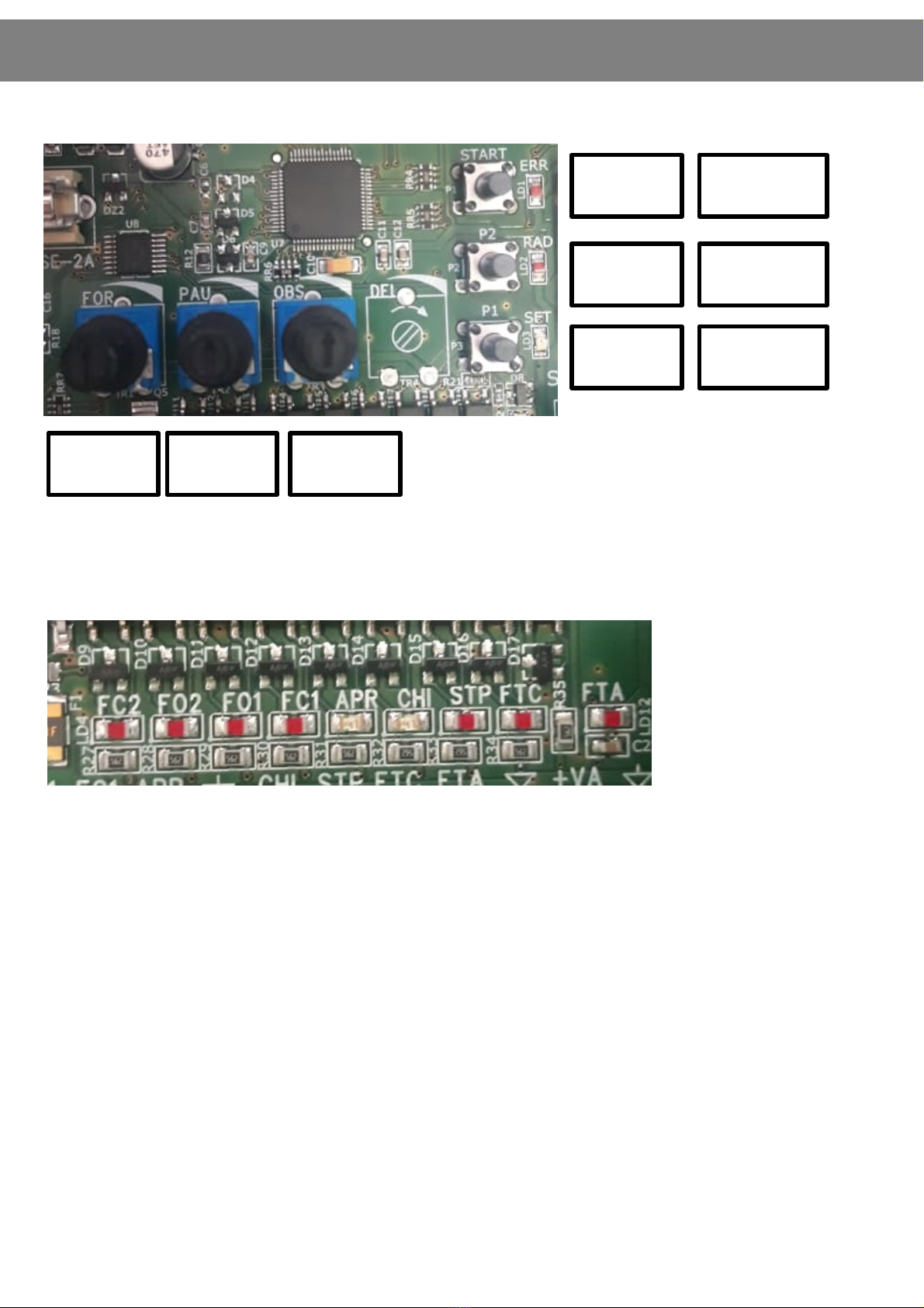
PROFESSIONAL learning
Slow down is setted by the operator
!!! ATTENTION !!!
A JUST TRIMMERS IF NECESSARY
!!! ATTENTION !!!
A trimmer variation “FOR” (speed) requires the repetition of the learning procedure from
The beginning (vary the manoeuvre time).
9

5. REMOTE CONTROLS
1 PRESS THE BUTTON P2 ON THE BOAR
2 THE RE LE LIGHTS UP
3 PRESS THE ESIRE BUTTON ON THE REMOTE CONTROL
4 RE LE PERFORMS 4 FLASHES TO IN ICATE THAT THE REMOTE IS MEMORISE
4.B RE LE BECOME RE
MEMORISE ALL THE REMOTE CONTROLS BY FOLLOWING ISTRUCTIONS FROM THE POINT 3
5 PRESS P2 FOR 2 SECON S
5. B WAIT UNTIL THE RE LE SWITCH OFF
6 REMOTE CONTROLS PROGRAMMATION FINISHE
MEMORISE ONE REMOTE CONTROL
ELETE REMOTE CONTROLS MEMORY
1 PRESS THE BUTTON P2 ON THE BOAR
2 RE LE FLASHES
3 PRESS AN KEEP PRESSE P2 FOR 5 SECON S
4 RE LE START FLASHING FASTLY
5 RE LE SWITCHES OFF
6 MEMORY ELETE
10

TRIMMER “FOR” - MOTOR SPEE
Trimmer “FOR” adjusts the voltage applied to the motors during operations, which means adjusting
the speed of the motors. With the trimmer turned fully counter-clockwise the speed of the motor if
50% of the maximum speed.
With the trimmer at half travel the speed of the motor if 50% of the maximum speed.
ATTENZION: Changing the setting of trimmer “FOR” requires repeating the learning procedure, since
the travel times and the slow-down start times change.
6. TRIMMERS AN A JUSTMENTS
TRIMMER “PAU” - PAUSE TIME
Switch the dip-switch 6 to OFF and the dip-switch 7 to ON.
Set the “PAU” trimmer in an intermediate position according to the pause time desired. The pause
time can be set between 3 and 60 seconds and is increased by rotating the trimmer clockwise.
TRIMMER “OBS” - OBSTACLE SENSITIVITY ETECTION
The “OBS” TRIMMER is used to adjust at the same time the delay time of intervention after an
obstacle has been detected and the threshold of the counter-force against the operator necessary to
trigger the intervention. Both the counter-force and the delay time increase when the trimmer is
turned clockwise. The delay time can be adjusted between 0.1 and 3 seconds. This function is useful
to overcome any critical points of the operator which cause a higher power absorption by the motor
for a short time..
11

1
2
3
4
5
6
7
8
ON FIRE ALARM ON THE CLAMP 12-13
OFF FIRE ALARM ISABLE
ON O NOT TOUCH – MANUFACTURER SETTINGS
OFF O NOT TOUCH – MANUFACTURER SETTINGS
ON PRESSURE SAFETY EVICE TYPE 8K2 ETENCTION
OFF PRESSURE SAFETY EVICE NC ETENCTION
ON OPEN BUTTON – CLOSE BUTTON
OFF START ON CLAMP 16/17 - STOP ON CLAMP 17/18
ON MOTOR ENCO ER ACTIVATE ( IF PRESENT )
OFF MOTOR ENCO ER ISABLE
ON STEP BY STEP MO E
OFF OPEN MO E
ON AUTOMATIC CLOSURE ENABLE
OFF AUTOMATIC CLOSURE ISABLE
ON BARRIER ALERT ISABLE
OFF OPEN BARRIER ALERT ENABLE
7. IP-SWITCHES
1. FIRE ALARM : if enabled, the barrier perform 1 open movement and remain in open position until
the contact will be NO again.
4. : If enabled, on the clamp 16-17connect one NO button for OPEN, on clamp 17-18 one NO
button for close
5. The board will check and detect if encoder is present on the motor. If not, the barrier will not
perform any movements
6. The logic is OPEN\STOP\CLOSE\STOP
For the open mode, the barrier will accept only an Open command.
8. if enabled, the board offer 1 dry contact for the OPEN BARRIER ALERT ( 24Vdc 3W max)
MAN PRESENT MO E
IP 6 = OFF
IP 7 = OFF
The buttons OPEN\CLOSE must be pressed until reaching the open\close limit switch
12

8. EXTERNAL BOAR S
BACKUP MEMORY
Inside there are all remote controls code and working
time.
Everytime one new remote control is memorized,
automatically it is trasnfered to the backup memory
TRANSFER ALL ATA FROM THE BACKUP MEMORY
. Remove power supply
. Insert backup memory
. Give power to the board
. When all the leds are off, press and keep pressed the
button P1 for 5 sec. Automatically the board check the
memory and trasnfers the contents
BATTERY CHARGER
The SIRIO 4 – 24 V control unit is fitted with an
automatic 13.7V C battery charger, for which a 12V
battery must be used, even for 24V C motors. In this
case, when there is no mains power the gate will travel
at half normal speed and the accessories will be
powered at 12V C. The 12V 1.2Ah buffer battery
allows a maximum of 5 reduced-speed manoeuvres
should the mains power supply be cutoff (as long as
the interruption occurred less than 24 hours earlier).
The control unit can manage batteries up to 7Ah (20-
30 complete
manoeuvres). The flashing light, when present, only
functions for the first 4 seconds of the manoeuvre. A
solar panel can be directly connected to the control
unit with a current regulator. The solar panel input is
already
protected by a diode.
+
-
!! RESPECT THE POLARITY !!
13

GREEN\RE LIGHTS ARE FOR
TRAFFIC LIGHT.
THESE CONTACTS ARE NOT
POWERE
MAX 5A 12V
MAX 5A 12V
- 24 V C LE FOR ARM
+ 24 V C LE FOR ARM
RY CONTACT FOR GREEN LIGHT
RY CONTACT FOR RE LIGHT
LIGHTS BOAR
8. EXTERNAL BOAR S
14

Yellow led SET:
- flashes for 5 seconds when turned on to indicate that it is possible to enter the Professional or
Simplified
Learning modes.
- lights up with a fixed light while Professional or Simplified Learning are carried out.
- is turned off when the control unit functions normally.
Red led ER:
- is turned off during normal control unit operations
- is alight (fixed light) when the control unit is blocked because it has failed the safety test or a motor is
disconnected
Red led RA :
- flashes briefly when a 433 MHz Multipass radio code is received
- is alight (fixed light) when radio codes are being memorised
- flashes rapidly when the control unit is switched on and the radio code memory is defective
- flashes rapidly during the cancellation of radio codes
- flashes slowly when there is an attempt to memorise new radio codes and the memory is full
- is switched off when the control unit is functioning normally and waiting to receive a command via
radio.
SCHE E ACCESSORI - COLLEGAMENTI9. LE S
15

1. LOOP ETECTORS CONNECTIONS
FUSE 2A FOR PAU OBS
1 2 3 4 5 6 7 8 9 10 11 12 13 14 15 16 17 18 19 20 21 22 23 24 25 26 27
28
29
SIRIO 4–24 V
SIRIO 4–24 V
START
P2\RAD
P1\SET
OPENING
LOOP ETECTOR
CLOSING
LOOP ETECTOR
SAFETY
LOOP ETECTOR
COMMON
NO CONTACT
NO CONTACT
COMMON
NC CONTACT
COMMON
NORMALLY
OPEN
NORMALLY
OPEN
NORMALLY
CLOSE

16-17 OPENING LOOP ETETCTOR 16. OPEN ( NO )
17. COMMON
18-17 CLOSING LOOP ETECTOR 18. CLOSE ( NO )
17. COMMON
19-22 EMERGENCY STOP
( INSERT A JUMPER IF NOT USE )
19, STOP ( NC )
22. COMMON
20-22 SAFETY LOOP ETECTOR 20. SAFETY LOOP CONTACT ( NC )
22. COMMON
21-22 PRESSURE SAFETY EVICE
( INSERT A JUMPER IF NOT USE )
21. ( NC )
22. COMMON
23-24 POWER SUPPLY 24VCC 23. + 24Vcc
24. - 24Vcc
ELECTRIC CONTACTS
AT THE EN OF ALL OPERATIONS
CHECK THE LE
STOP – FTC – FTA
THEY MUST BE ACTIVETE
IN OR ER TO HAVE A GOO LOOP ETECTOR,
WITHOUT ANY WRONG ETECTION
THE FEE ER PORTION OF THE CABLE HAS TO
BE HIGHLY TWISTE
LOOP CABLES

WARNINGS!!!
OUR COMPANY, AS MANUFACTURER, CAN NOT BE HELD RESPONSIBLE FOR DAMAGES DUE TO WRONG OR MISSING
CONNECTIONS OR DUE TO AN IMPROPER SETTING.
THE SAFETY DEVICES SHOULD BE ALWAYS INSTALLED AND KEPT IN FULL WORKING ORDER.
ONCE TERMINATED THE SYSTEM SETTING, YOU SHOULD PLACE BACK THE CONTAINER ON ITS POSITION,
FASTENING TIGHT ITS SCREWS.
OUR COMPANY, AS MANUFACTURER, CAN NOT BE HELD RESPONSIBLE FOR DAMAGES DUE TO IMPROPER USE OF
THE DOOR/GATE.
IT IS FORBIDDEN TO REPLACE ANY ELECTRIC, ELECTRONIC OR MECHANIC PART WITH NOT ORIGINAL OUR
COMPANY SPARE PARTS.
OUR COMPANY, HAS THE RIGHT TO MODIFY OR CHANGE THE ELECTRONIC BOARDS AND MANUALS, WITHOUT PRIOR
NOTICE.
ALWAYS REGULATE ACCURATELY THE TORQUE OF THE MOTORS. AN INCORRECT SETTING OF THE TORQUE, MAY
CAUSE DAMAGE TO PEOPLE, ANIMALS OR OBJECTS.
WARRANTY:
Devices and accessories are guaranteed for a period of 24 months after production, whose date
is printed on each item. The compan will replace or repair its devices, provided that the are
returned to our factor with the warrant label in good conditions. In case of replacement of the
returned items, these will remain propert of the compan .
The warrant does not include damages due to an incorrect use, such as: non fulflment of the
instruction detailed for each device, maintenance and servicing carried out without the previous
written consent of our compan . Moreover, warrant does not cover an damage due to wrong
tension suppl and an other reason for which the manufacturer cannot be made responsible. An
device returned must be delivered to our compan with carriage paid and will be sent back with freight
collect.
Warrant validit ceases if customer’s pa ments are not fulflled. Each device manufactured b
our compan meets the european safet standards.
Our compan declines all responsibilit for the non-observance of the safet rules b the
installers.
In order to red ce the time spent for servicing the ret rned items, all fa lty materials which
have been sent back to s m st be accompanied by the installer description of the item
fa lt.
BAME s.r.l. - Via L. da Vinci, 23 - 46020 SAN GIACOMO SEGNATE (MN) - ITALY
Tel. +39 0376 616 638 - Fax +39 0376 629 456 - http://www.bame.it - http://www.delma.it
Unità locale: Via Enrico Berlinguer, 6 - 63844 GROTTAZZOLINA (FM) - ITALY
Tel. +39 0734 633 533 - Fax +39 0734 636 895 - e-mail: delma@bame.it - venditedelma@bame.it

BAME s.r.l. - Via L. da Vinci, 23 - 46020 SAN GIACOMO SEGNATE (MN - ITALY
Tel. +39 0376 616 638 - Fax +39 0376 629 456 - http://www.bame.it - http://www.delma.it
Unità locale: Via Enrico Berlinguer, 6 - 63844 GROTTAZZOLINA (FM - ITALY
Tel. +39 0734 633 533 - Fax +39 0734 636 895 - e-mail: delma@bame.it - venditedelma@bame.it
Table of contents
Other Bame Control System manuals
Popular Control System manuals by other brands

heat-timer
heat-timer 928051-50-VM Installation and operation manual

Siemens
Siemens SINUMERIK ONE MCP 2400.4c Equipment manual

Gossen MetraWatt
Gossen MetraWatt U1601 operating instructions

Kemper
Kemper KHS MASTER 2.1 Installation and operating instructions

Frico
Frico FC Series Original instructions

Penn
Penn System 450 Series installation guide