Tiger Optics HALO M7000 Series User manual

HALO!Trace Gas Analyzer
Instruction Manual
M7000 Series
Rev G

HALO Users Manual Revision G
ii
Thank You
Dear Customer,
We commend you on your selection of the Tiger Optics HALO™ Trace Gas Analyzer. We
appreciate the time, effort, and money you devoted to selecting the equipment best suited to
your needs. We respect the fact that, by purchasing our equipment, you show your faith in our
technology and our organization. Therefore, we pledge to repay you with exceptional quality,
service, and support.
Tiger Optics provides instrumentation of the highest quality and finest precision for some of
industry's toughest analytical and measurement tasks. As the field of moisture analysis grew
and changed over the past few decades, our experienced design team led in product
innovation. Thus, our second pledge to our customers is to continue to keep pace with market
needs now and long into the future.
Finally, thank you for choosing a Tiger Optics HALO™ Trace Gas Analyzer. Please remember
that we value your opinion as much as your patronage. We welcome your comments,
questions, and suggestions about our equipment.
Sincerely,
The Tiger Optics Staff
" 2006 Tiger Optics, LLC All rights reserved. No part of this publication may be reproduced, transmitted,
transcribed, stored in a retrieval system, or translated into any language in any form by any means
without the written permission of Tiger Optics.
HALO! is a trademark of Tiger Optics LLC.
Teflon® is a registered trademark of E.I. DuPont de Nemours and Company
Snoop® is a registered trademark of the Swagelok Company
VCR® is a registered trademark of the Swagelok Company
Tiger Optics LLC, 250 Titus Avenue, Warrington, PA 18976, U.S.A.
(215) 343-6600, FAX (215) 343-4194 http:// www.tigeroptics.com

HALO Users Manual Revision G
iii
TIGER OPTICS WARRANTY
Tiger Optics, LLC warrants all equipment manufactured and repaired to be free from defects in material
and workmanship, given proper use and service. Tiger Optics’ obligation under this warranty is limited to
repairing or, if necessary, replacing any article of equipment within one (1) year from date of shipment,
without charge, F.O.B. Tiger Optics’ factory. Such equipment or parts must be returned to Tiger Optics
(transportation prepaid). Parts and service repairs are warranted against manufacturer’s defects for 90
days. Please contact Tiger Optics’ Service Department for a Return Authorization (RA) number prior to
returning the unit. All units and/or cells returned without an RA number may be sent back at customer
expense. Units manufactured seven (7) years prior or older, may not be repairable based on available
components. Please contact the Tiger Optics Service Department prior to returning the unit.
Items considered expendable, such as fuses are not under warranty. This warranty shall not apply to
equipment and parts repaired or altered outside of Tiger Optics’ factory or its authorized service centers.
It also does not apply to equipment and parts subjected to negligence, accidental damage or improper
installation, or use not in accordance with the instructions provided in the instruction manual. Tiger Optics
LLC, neither assumes, nor authorizes any other persons to assume for it, any liability in connection with
the sales of its products.
Tiger Optics Service
Phone: (215) 343-6600
250 Titus Avenue
FAX: (215) 343-4194
Warrington, PA 18976
Toll Free: (800) 641-6478
HALO Users Manual Revision G
iv
IMPORTANT CAUTION SYMBOLS
Warning! Labels
NOTE: Before operating the HALO please be sure to read all the warning or caution
notes, which are shown throughout the manual. We have listed all of the warning
notes on this page for your convenience. You must read this instruction manual
completely before operating your HALO. Failure to do so may cause damage to
your unit.
Use of this analyzer with gases that are toxic, explosive, or those which may create explosive
mixtures (like hydrogen and oxygen), requires complete purging with an inert gas. Failure to
remove all gas residue by not purging with an inert gas will expose you to risk of injury or
explosion.
Use only an approved detachable power cord. (1 meter, 120V or 220V, 2 pole, 3 wire, ground,
15 amp power cord)
Disconnect the analyzer from AC power source before performing any maintenance or repair
function inside the case.
This CAUTION symbol alerts the user to information regarding personal safety.
This HIGH VOLTAGE symbol indicates the presence of a high voltage danger.
This CAUTION symbol alerts the user to the presence of laser radiation.

HALO Users Manual Revision G
v
Table of Contents
List of Tables vii
1Theory of Operation 1
1.1 Cavity Ringdown Spectroscopy 1
1.2 How it Works 1
2Specifications and Drawings 4
2.1 Specifications 4
2.2 Dimension Drawing 8
2.3 Dimension Drawing of a Single HALO Unit 9
2.4 Front Panel of HALO Unit 10
2.5 Rear Panel of HALO Unit 11
3Installing Your HALO 12
3.1 Overview 12
3.2 Unpacking Your HALO 12
3.3 Serial Number Identification 14
3.4 Preparing the Sample Line 15
3.5 Assembling the Sample Line 16
3.6 Leak-Testing the Sample Line 17
3.7 HALO Location 18
3.8 Pressure and Venting Considerations 19
3.9 Connection Considerations 20
3.10 Connecting to the Sample Inlet and Outlet 21

HALO Users Manual Revision G
vi
3.11 Powering On and Configuration 22
3.12 Capping the Sample Inlet and Outlet to Avoid Contamination 23
4Basic Operation 24
4.1 Introduction 24
4.2 User Interface 24
4.3 Modes of Operation 30
4.4 Other Toolbar Functions 31
4.5 Ringdown Alarm 32
5Data Capture Guide 33
5.1 Setting up the Connection 33
5.2 Saving Data to a Text File 35
5.3 Deleting Data from HALO Memory 35
6Remote Operations 36
6.1 Overview 36
6.2 Interfacing 36
6.3 Commands 37
7Troubleshooting and Maintenance 43
7.1 General Information 43
7.2 Preventive Maintenance 43
7.3 Troubleshooting Guide 44
7.4 Return a Unit for Repair 45
8Special Considerations for H2O Measurement 47

HALO Users Manual Revision G
vii
List of Tables
Table 2-1 HALO-H2O Trace Gas Analyzer Specifications ....................................... 4
Table 2-2 HALO-CH4Trace Gas Analyzer Specifications........................................ 6
Table 3-1 Unpacking Your HALO ............................................................................ 12
Table 3-2 Procedure for Preparing the Sample Line ............................................. 16
Table 3-3 Procedure for Leak-Testing the Sample Line........................................ 17
Table 3-4 HALO Location......................................................................................... 18
Table 3-5 Connecting to the Sample Inlet and Outlet............................................ 21
Table 3-6 Capping the Sample Inlet and Outlet ..................................................... 23
Table 6-1 RS-232 DB-9F Pin Designation ............................................................... 36
Table 6-2 Host to HALO Connections..................................................................... 36
Table 7-1 Troubleshooting ...................................................................................... 44
List of Figures
Figure 1-2 Ringdown Time ....................................................................................... 2
Figure 1-3 Absorption Spectrum.............................................................................. 2
Figure 1-4 Concentration (N) Calculation................................................................ 3
Figure 2-1 HALO Two Unit Dimension Drawing ..................................................... 8
Figure 2-2 HALO Single Unit Dimension Drawing.................................................. 9
Figure 2-3 HALO Two Unit Front Panel ................................................................. 10
Figure 2-4 HALO Two Unit Rear Panel .................................................................. 11
Figure 3-1 Serial Number Identification................................................................. 14

HALO Users Manual Revision G
viii
Figure 3-2 Alarm Relay and mA Output Connector.............................................. 18
Figure 3-3 Flow Diagram......................................................................................... 20
Figure 4-1 Virtual Keypad ....................................................................................... 24
Figure 4-2 Main Display .......................................................................................... 25
Figure 4-3 Gas Type Setup Tab of the Settings Window ..................................... 26
Figure 4-4 Output and Communications Tab of the Settings Window ............... 27
Figure 4-7 Operating Mode Select Window........................................................... 30
Figure 4-8 Trend Graph........................................................................................... 31
Figure 4-9 Ringdown Signal ................................................................................... 32
Figure 5-1 Connection Setup Windows................................................................. 33
Figure 5-2 Port Settings, HALO Properties, and ASCII Setup ............................. 34
Figure 5-3 Connection Test .................................................................................... 34
Figure 5-4 Capture Text .......................................................................................... 35

HALO Users Manual Revision G
1
1 Theory of Operation
1.1 Cavity Ringdown Spectroscopy
Based on absorption spectroscopy, Cavity Ringdown Spectroscopy (CRDS) works by
attuning light rays from a Continuous Wave (CW) laser to a wavelength within the IR
spectrum where a contaminant absorption peak occurs (Figure 1-3). By measuring the time
it takes for the light to fade, or “ringdown” an accurate molecular count is calculated that is
not pressure sensitive. The time of light decay, in essence, provides an exact, non-invasive,
and rapid means to detect contaminants in gases.
1.2 How it Works
# A Continuous Wave (CW) diode laser emits a directed beam of light energy through an
ultra-high reflective mirror into the absorption cell (cavity).
Figure 1-1 Cavity Ringdown Spectroscopy
# The light reflects back and forth between two ultra-high reflective mirrors multiple times
# On each successive pass, a small amount of light or ringdown signal emits through the
second mirror and is sensed by the light detector
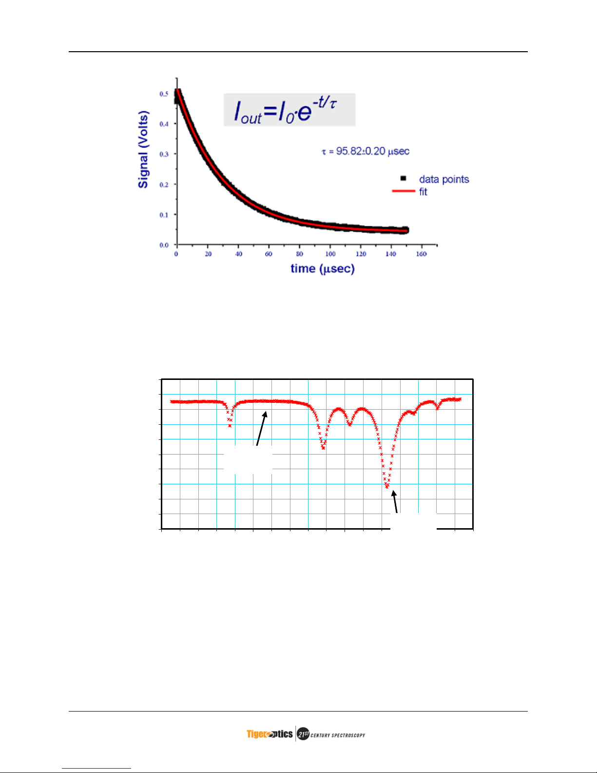
# Once the photodiode detector “sees” a preset level of light energy, the light source is
shuttered, or diverted from the cavity (time ~ 0 Figure 1-2)
# Once the light decays, or “rings down”, the detector achieves a point of zero light energy
in microseconds, and the measurement is complete (time ~ 150 Figure 1-2). This decay
is exponential, and described by the equation listed in Figure 1-2.
Light
Source
Light
Detector
Highly
Reflective
Mirrors
HALO Users Manual Revision G
2
Figure 1-2 Ringdown Time
# The computer-controlled system tunes the laser off the absorption peak for the sample
species to determine the “tau zero” value, equivalent to a zero baseline (Figure 1-3).
Figure 1-3 Absorption Spectrum
# The concentration of the sample species is calculated (Figure 1-4) by comparing this “tau
zero” value to the ”tau measured” ringdown time.
# These calculations are based on first principles and follow the Beer-Lambert Law.
0
10
20
30
40
50
60
70
80
90
100
1391.3 1391.8 1392.3 1392.8
Wavelength (nm)
$(%sec)
&'(&$zero
&'(&$peak

HALO Users Manual Revision G
3
)1( Rc
d
zero )
*
$
))()1((
)( NdRc
d
+,
+
$
-)
*
)
1
)(
1
(
)(
1
z
ero
c
N
$+$+,
)*
c = Speed of Light != Absorption Cross Section
d = Cell Length $(+)="Ringdown Time
R = Reflectivity of the Mirror += Laser Frequency
N = Molecular Density
(concentration)
Figure 1-4 Concentration (N) Calculation

HALO Users Manual Revision G
4
2 Specifications and Drawings
2.1 Specifications
Table 2-1 HALO-H2O Trace Gas Analyzer Specifications
Performance
Lowest Detection Limit 2 ppb
Sensitivity 1 ppb
Accuracy 4% of reading or +/- 1 ppb if greater
Speed of Response
(typical)
Dry down response from 1ppm intrusion to 90% of final value in
<3min
Wet up response to 1ppm intrusion – 90% of final value in <2min
Operating Range 0 – 20000 ppb
Environmental Conditions 10º - 40ºC - - - 30% to 80% R.H. Non-condensing
Storage Temperature -10°C to 50°C
Technology
Method Cavity Ring-Down Spectroscopy (CRDS)
Laser Light Source Continuous Wave (CW) Near-IR diode laser
Approvals CE Marked – LVD and EMC approved
Patents U.S. Patent # 5,528,040
U.S. Patents Pending
Gas Sample Conditions
Sample Inlet Pressure 10 – 125 psig (1.7 – 9.6 bara)
Sample Outlet Pressure < 2.0 psig back pressure (or vacuum)
Flow Rate 0.5 to 1.8 slpm depending on gas type
Sample Gases
Ar, H2, HBr, HCl, He, N2, O2, SF6, CF4, Cl2, CO2, CDA, and CO
(contact Tiger Optics for additions to the list of sample gases).
Sample line temperature Up to 60ºC

HALO Users Manual Revision G
5
Gas Flow System
Wetted Components 316L stainless steel (optional: Hastelloy ®), Elgiloy, PCTFE, 304
stainless steel, fused silica, nickel plated stainless steel, and
nickel plated copper.
Surface Finish of Wetted
Components
10 Ra
Fittings and Connections ¼” VCR-type
Leak tested to: < 2 x 10⁻⁸ mbar · liter /sec
Electrical
Power Requirements 90-250 VAC 50/60 Hz
Power Consumption 40 Watts max
Alarm Indicators User programmable alarm set points
Output Signals
Recorder
Alarm
Isolated 4-20 mA output
2-Form-C relay (user configurable)
1-Form-C relay for system fault monitoring (Laser status &
ringdown status)
802.11g Wireless (optional)
User Interface 5.6” Color LCD display with touch screen
10BaseT Ethernet, RS-232 (can be changed to RS-422)
Mounting and Hook-up Considerations
Configuration 2 Units per 19” relay rack or mobile cart mount
Dimensions Individual Module –
8.73”h x 8.57”w x 23.58”d (22.2cm x 21.7cm x 59.9cm)
Two Modules in rack housing –
8.73”h x 17.5”w x 23.58”d (22.2cm x 44.5cm x 59.9cm )
Weight Individual Module –
28 lbs. (12.7 kg)

HALO Users Manual Revision G
6
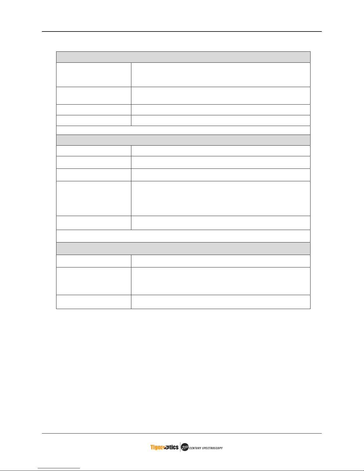
Table 2-2 HALO-CH4Trace Gas Analyzer Specifications
Performance
Lowest Detection Limit 4 ppb
Sensitivity 2 ppb
Accuracy 4% of reading or +/- 2 ppb if greater
Speed of Response
(typical)
Dry Down Response to 50ppb intrusion - 90% of final value in
<1min
Operating Range 0 – 8000 ppb
Environmental Conditions 10º - 40ºC - - - 30% to 80% R.H. Non-condensing
Storage Temperature -10°C to 50°C
Technology
Method Cavity Ring-Down Spectroscopy (CRDS)
Laser Light Source Continuous Wave (CW) Near-IR diode laser
Approvals CE Marked – LVD and EMC approved
Patents U.S. Patent # 5,528,040
U.S. Patents Pending
Gas Sample Conditions
Sample Inlet Pressure 30 – 125 psig (3.1 – 9.6 bara)
Sample Outlet Pressure < 2.0 psig back pressure (or vacuum)
Flow Rate 0.5 to 1.8 slpm depending on gas type
Sample Gases
N2, He, Ar, H2, and O2 (contact Tiger Optics for additions to the
list of sample gases).
Sample line temperature Up to 60ºC
HALO Users Manual Revision G
7
Gas Flow System
Wetted Components 316L stainless steel (optional: Hastelloy ®), Elgiloy, PCTFE, 304
stainless steel, fused silica, nickel plated stainless steel, and
nickel plated copper.
Surface Finish of Wetted
Components
10 Ra
Fittings and Connections ¼” VCR-type
Leak tested to: < 2 x 10⁻⁸ mbar · liter /sec
Electrical
Power Requirements 90-250 VAC 50/60 Hz
Power Consumption 40 Watts max
Alarm Indicators User programmable alarm set points
Output Signals
Recorder
Alarm
Isolated 4-20 mA output
2-Form-C relay (user configurable)
1-Form-C relay for system fault monitoring (Laser status &
ringdown status)
802.11g Wireless (optional)
User Interface 5.6” Color LCD display with touch screen
10BaseT Ethernet, RS-232 (can be changed to RS-422)
Mounting and Hook-up Considerations
Configuration 2 Units per 19” relay rack or mobile cart mount
Dimensions Individual Module –
8.73”h x 8.57”w x 23.58”d (22.2cm x 21.7cm x 59.9cm)
Two Modules in rack housing –
8.73”h x 17.5”w x 23.58”d (22.2cm x 44.5cm x 59.9cm )
Weight Individual Module –
28 lbs. (12.7 kg)

HALO Users Manual Revision G
8
2.2 Dimension Drawing
The HALO dimensions of the front, rear and side views are shown in Figure 2-1. Two analyzers
will fit into a 19” relay rack.
Figure 2-1 HALO Two Unit Dimension Drawing

HALO Users Manual Revision G
9
2.3 Dimension Drawing of a Single HALO Unit
Figure 2-2 HALO Single Unit Dimension Drawing
HALO Users Manual Revision G
10
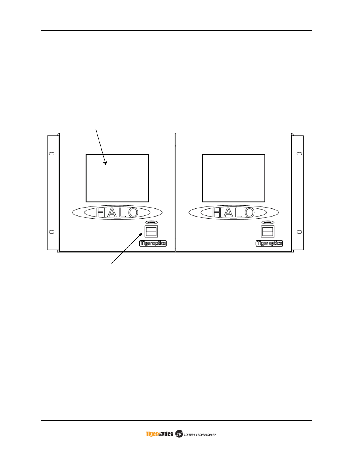
2.4 Front Panel of HALO Unit
Figure 2-3 HALO Two Unit Front Panel
Color LCD Display and
Touch Screen
Power Switch

HALO Users Manual Revision G
11
2.5 Rear Panel of HALO Unit
Figure 2-4 HALO Two Unit Rear Panel
Sample Inlet Sample Outlet
RS-232 Connection I/O Connection
Power Connection Ethernet Connection

HALO Users Manual Revision G
12
3 Installing Your HALO
3.1 Overview
Once you receive the HALO analyzer, the basic steps to install it are:
# Unpack and inspect the unit
# Identify serial number
# Prepare the sample line
# Make electrical connections
# Connect the sample inlet and outlet
3.2 Unpacking Your HALO
Table 3-1 Unpacking Your HALO
Step Action
1 Inspect the shipping carton prior to opening. If any damage is
apparent, immediately notify the shipping company and Tiger
Optics. Do not proceed with installation.
2 Remove the analyzer from its carton and again, examine the unit
for damage. If damage is apparent, immediately notify the
shipping company and Tiger Optics. Do not proceed with
installation.
3 Check the carton contents against the packing slip to ensure the
shipment is complete. Each HALO will include separately at least
the following items:
- Power cord
- Certificate of calibration
- Quick Start Guide
- RS-232/USB converter cable
Any missing items should be reported to Tiger Optics
immediately.
4 The HALO is shipped ready for use. To keep the Ring-Down
Cavity dry and clean during shipping the gas inlet and outlet
connections are capped. To avoid contamination these caps
must stay in place until the unit is connected to the gas supply.
5 Record the model number and serial number in your permanent
record file. You will need these numbers for any future communication
with Tiger Optics. A description of the serial number follows this
section.
ATTENTION: Save Caps!
Save the gas inlet and outlet caps. Whenever the unit is not connected to gas, put
these caps back on the inlet and outlet fittings to keep the Ring-Down Cavity and
internal tubing clean and free of contamination.
Table of contents
Popular Measuring Instrument manuals by other brands

Endress+Hauser
Endress+Hauser COM 381 operating instructions

MAGEE Scientific
MAGEE Scientific Aethalometer AE33 user manual

Solinst
Solinst 9700 SolSat 5 quick start guide

Omega
Omega LVCN-40 Series user guide

Fema Electronica
Fema Electronica BDF Series user manual

Seikom Electronic
Seikom Electronic RLSW 8 LCD user manual


Hy-Gain
Hy-Gain 421A Installation and operation instruction

Emerson
Emerson World Class 3000 instruction manual

Keysight Technologies
Keysight Technologies N9320A RF Configuration guide

oxford diffraction
oxford diffraction Xcalibur A user manual

Sonic Meter
Sonic Meter Sonic AO operating manual

HBM
HBM KMR Mounting instructions