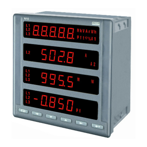
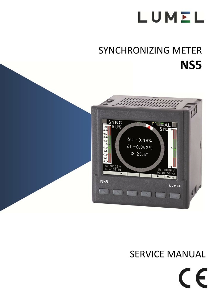
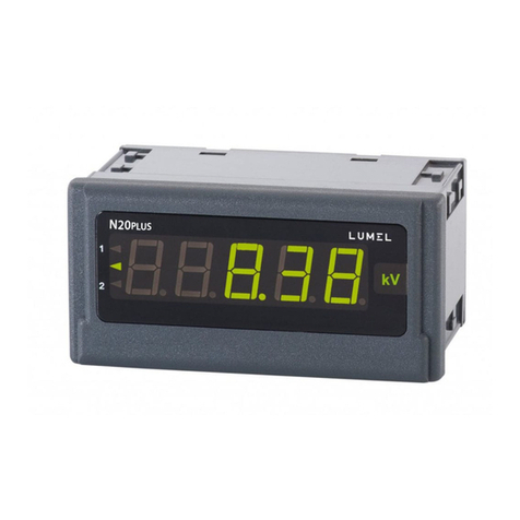
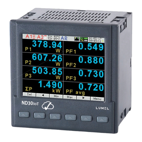
Lumel ND40 User manual

POWER NETWORK ANALYZER
ND40
USER’S MANUAL - QUICK START
Full version of user’s manual available at
www.lumel.com.pl
Scan the code

ND40-09-2D - User's manual
2
Table of contents
1. General Specification.......................................................................................................................3
1.1. Features of the Device...............................................................................................................3
1.1.1. Operational safety ..............................................................................................................4
1.2.1. Connection diagrams..........................................................................................................4
1.2.1.1. Measurement signals.......................................................................................................5
1.2.1.2. Communication interfaces ..............................................................................................9
1.2.1.3. Card of 8 Relay outputs ..............................................................................................9
1.2.1.4. Card of 6 Binary inputs 4 relay outputs .......................................................................10
1.2.1.5. Card for 6 binary inputs and 3 Analog outputs ............................................................ 11
1.2.1.6. Card for 4 binary inputs and 6 Analog outputs ............................................................12
1.2.2. Installation........................................................................................................................13
2. Operation........................................................................................................................................15
2.1. Description of Control Panel functions...................................................................................17
2.2. Web server...............................................................................................................................18
2.3. SD memory card .....................................................................................................................19
2.4. Update .....................................................................................................................................19
3. Technical data.................................................................................................................................20
3.1. Measurements .........................................................................................................................20
3.2. Expansion cards ......................................................................................................................25
3.2.1 3 galvanically isolated analog outputs .........................................................................25
3.2.2 6 galvanically isolated analog outputs .........................................................................25
3.2.3 Binary inputs .....................................................................................................................26
3.2.4. Alarm outputs...................................................................................................................26
3.3. Reference conditions and rated operating conditions .............................................................26
3.4. Operating safety acc. to EN 61010-1, basic isolation ............................................................26
3.5. Electromagnetic compatibility ................................................................................................ 27
3.6. Assembly.................................................................................................................................27
3.7. Conformity with standards......................................................................................................27
4. Ordering codes ...............................................................................................................................28

ND40-09-2D - User's manual
3
1. General Specification
The ND40 Meter is designed for the measurement and analysis of three-phase, 3- or 4-wire power
network parameters in balanced or unbalanced systems.
Complete set of the Analyzer includes:
ND40 Meter 1 pc
abbreviated User’s Manual 1 pc
mounting brackets to fix the device in the panel 4 pcs
key 1 pc
warranty card 1 pc
ferrite filter STAR-TEC 74271132 1 pc
SD card 1 pc
Caution! On the SD card is located ND40 Setup software and user manual.
1.1. Features of the Device
measurement and calculation of energy quality parameters according to EN 50160 standard.
intuitive operation of the device by means of the touch screen and graphical user interface
based on Linux.
color touch screen LCD TFT 5,6'', 640x480 pixels
communication interfaces : Ethernet 10/100 Base-T, Modbus TCP/IP Slave, RS-485 Modbus
Slave
all phases are separated
IP65 enclosure protection of the user
selection of the time zone, automatic adjustment for Daylight Saving Time, synchronization
with the time serv
data archiving on an SD card
WWW server, FTP server
logs of interrupts, dips, swells, alarms and audits
Firmware update option
language choice Polish/English
dedicated visualization in the form of, among others: digital, analog displays, harmonics,
vector diagrams, trends, waveforms records

ND40-09-2D - User's manual
4
1.1.1. Operational safety
Caution! Removal of the meter housing during the warranty period voids the warranty.
The assembly and the installation of the electrical connections may be carried out only by a
duly qualified electrician.
Always check the connections before turning the meter on.
Prior to removing the analyzer housing, always turn the supply off and disconnect the
measurement circuits.
The device is intended for installation and use in industrial electromagnetic environments.
A switch or a circuit-breaker should be installed in the building or facility. It should be
located near the device, easily accessible to the operator, and suitably marked.
1.2.1. Connection diagrams
Caution! PE conductor must be connected.
Model
No.
Description
Fig.1. Terminal plate.1
1
Measurement output of electrical
parameters.
2
Additional inputs/outputs - optional
equipment depending on ND40 execution
code. There are relay outputs, binary inputs
and analog outputs.
3
Measurement inputs of temperature and
resistance.
4
Ethernet communication interface.
5
RS 485 Modbus Slave communication
interface.
6
ND40 analyzer power supply.
7
Earth terminals for screens connection.

ND40-09-2D - User's manual
5
1.2.1.1. Measurement signals
3-wire network. Direct measurement.
Fig.2. Diagram - 3-wire network.
3-wire network. Semi-indirect measurement.
Fig.3. Diagram - 3-wire network.

ND40-09-2D - User's manual
6
3-wire network. Indirect measurement using two current transformers and two or three voltage
transformers.
Fig.4. Diagram - 3-wire network.
4-wire network. Direct measurement.
Fig.5. Diagram - 4-wire network.

ND40-09-2D - User's manual
7
4-wire network. Semi-indirect measurement.
Fig.6. Diagram - 4-wire network.
4-wire network. Semi-indirect measurement using four current transformers.
Fig.7. Diagram - 4-wire network.

ND40-09-2D - User's manual
8
4-wire network. Indirect measurement using three current transformers and two or three voltage
transformers.
Fig.8. Diagram - 4-wire network.
4-wire network. Indirect measurement using 4 current transformers and two or three voltage
transformers.
Fig.9. Diagram - 4-wire network.

ND40-09-2D - User's manual
9
1.2.1.2. Communication interfaces
Ethernet (RJ45) socket.
To connect the meter to the hub (concentrator) or the
switch, it is necessary to use a cable with 1:1 leads.
RS485 interface(Slave) is assigned jto terminal pairs 33-
34 and 36-37.
Fig.10. Com. Interfaces.
1.2.1.3. Card of 8 Relay outputs
Relay outputs configured as normally open (NO).
Where:
terminals 13-14: output 1, terminals 21-22: output 5,
terminals 15-16: output 2, terminals 23-24: output 6,
terminals 17-18: output 3, terminals 25-26: output 7,
terminals 19-20: output 4, terminals 27-28: output 8.
Version with 8 relays uses the upper and lower part
of the expansion card terminal, terminals from 13 to 28.
‘
Fig.11. Relay outputs

ND40-09-2D - User's manual
10
1.2.1.4. Card of 6 Binary inputs 4 relay outputs
Connection of relay outputs
Relay outputs configured as normally open (NO).
where:
terminals 13-14: output 1,
terminals 15-16: output 2,
terminals 17-18: output 3,
terminals 19-20: output 4,
Version with 4 relays uses the upper part of the expansion card
terminal, terminals from 13 to 20.
Fig.12. Relay inputs.
Connection of binary outputs
Fig.13. Binary inputs.

ND40-09-2D - User's manual
11
Binary inputs BI 1...BI 6 are controlled by signals:
0 V dc –inactive binary input
+5...24 V dc –active binary input
+8...24 V dc –input as counting input (high level)
Where:
terminal 21 : binary input BI 1, terminal 25 : binary input BI 4,
terminal 22 : binary input BI 2, terminal 26 : binary input BI 5,
terminal 23 : binary input BI 3, terminal 27 : binary input BI 6.
terminal 24: common terminal for inputs BI 1-3
terminal 28: common terminal for inputs BI 4-6
1.2.1.5. Card for 6 binary inputs and 3 Analog outputs
Connection of analog outputs
Version with analog inputs uses the upper part of the expansion
card terminal and includes 3 pairs of terminals:
13 - 14 analog output 1 (AO1)
16 - 17 analog output 2 (AO2)
19 - 20 analog output 3 (AO3)
Fig.14. Analog outputs

ND40-09-2D - User's manual
12
Connection of binary outputs
Fig.15. Binary outputs
Binary inputs BI 1...BI 6 are controlled by signals:
0 V dc –inactive binary input
+5...24 V dc –active binary input
+8...24 V dc –input as counting input (high level)
Where:
terminal 21 : binary input BI 1, terminal 25 : binary input BI 4,
terminal 22 : binary input BI 2, terminal 26 : binary input BI 5,
terminal 23 : binary input BI 3, terminal 27 : binary input BI 6.
terminal 24: common terminal for inputs BI 1-3
terminal 28: common terminal for inputs BI 4-6
1.2.1.6. Card for 4 binary inputs and 6 Analog outputs
Connection of analog outputs
Version with analog inputs uses both part of the expansion card terminal and includes 6 pairs
of terminals:
13 –14 : analog output 1 (AO1)
16 –17 : analog output 2 (AO2)
19 –20 : analog output 3 (AO3)
21 –22 : analog output 4 (AO4)
24 –25 : analog output 5 (AO5)
27 –28 : analog output 6 (AO6)
Fig.16. Analog outputs

ND40-09-2D - User's manual
13
Connection of binary outputs
Fig.17. Binary outputs
Binary inputs BI 1...BI 4 are controlled by signals:
0 V dc –inactive binary input
+5...24 V dc –active binary input
+8...24 V dc –input as counting input (high level)
Where:
terminal 41 : binary input BI 1, terminal 44 : binary input BI 4,
terminal 42 : binary input BI 2, terminal45 : common terminal for inputs BI 1-4
terminal 43 : binary input BI 3,
1.2.2. Installation
ND40 analyzer is adapted to be fixed to the panel by means of mounting brackets. Housing
dimensions 144 x 144 x 104 mm, mounting hole dimensions 138 x 138 mm.

ND40-09-2D - User's manual
14
Fig.14. Dimensions - bottom.
Fig.15. Dimensions - front.
Fig.16. Dimensions - side.
Fig.17. Dimensions - mounting hole.

ND40-09-2D - User's manual
15
2. Operation
After touching any area of the screen, the set of the analyzer’s management and navigation tools is
displayed.
Description of individual elements to operate the analyzer available to the user.
Example
No.
Description
Fig.22. Main screen.
1
Change of view (selection list)
2
Change of the current view screen (selection
list)
3
SD card status
4
Alarms status (the symbol and the change of
the upper bar to red color)
5
Current time and date
6
Change of the current view screen
7
Change of the view
8
Switching to the Control Panel.
9
System information
10
Options available for the selected view
List of sample screen available in ND40.
Screen
Example
Screen
Example
Large digital
view
Fig.23. Screen 1.
Vector diagram
Fig.24. Screen 6.

ND40-09-2D - User's manual
16
Analog
indicators
Fig.25. Screen 2.
Waveform
Fig.26. Screen 7.
Trends
Fig.27. Screen 3.
Temperature
/ Resistance
Fig.28. Screen 8.
Harmonics
Fig.29. Screen 4.
Binary inputs
Fig.30. Screen 9.
Energy
Fig.31. Screen 5.
Logs
Fig.32. Screen 10.

ND40-09-2D - User's manual
17
2.1. Description of Control Panel functions
Fig.33. Control panel - main screen.
No.
Description
1
General settings of the analyzer, e.g. date, time, display settings.
2
Configuration of measurement inputs, e.g. transformers, ranges, frequencies,
temperature/resistance sensors.
3
Alarms settings, e.g. setting the source, activate/deactivate conditions, relays, handling e-mails
informing about events.
4
Settings of screens and views. Management of defined date sets and creation of user’s data sets.
5
Setting the analyzer’s identification in Ethernet network, configuration of FTP, WWW, SMTP
servers and e-mail.
6
Settings of Modbus RTU and TCP/IP transmission and other communication protocols.
7
Configuration of archiving parameters and conditions.
8
Management of users rights, setting passwords and access rights.
9
Setting parameters for dips, interrupts and swells.
10
Configuration of parameters for analog outputs and relays (depending on the version)
11
Information about the analyzer, updating module.
12
Completion of work in the Control Panel, saving configuration changes and export of settings to a
file.

ND40-09-2D - User's manual
18
2.2. Web server
Depending on the settings, access to the Web server may be preceded by verification of users,
available anonymously (without the login window) or turned off.
Fig.30. Web server - general view.
No.
Description
1
IP address assigned to the device. Address check or change in Ethernet tab in the Control
Panel.
2
Password and login. Standard login: Admin, no password. Possible edition of the access in
Ethernet tab (users and rights) in the Control Panel.
3
Switching to the main page is preceded by user verification.
4
Web server main page window.
5
Data presentation module with selectable refresh time and default or user generated sets of data
presentation.
6
Additional options, depending on user rights.
7
Alarm module with possibility to preview and confirm events.
8
Managing files on the SD card
9
Information module.

ND40-09-2D - User's manual
19
2.3. SD memory card
Sample files are stored on SD card.
Function
Sample file
Description
Archive
2016-01-19 08_16_46.ND40Arch
Archive file with the option of preview and
export to csv. Format compatible with SQLite.
Configuration
Config_20160112_1727.ND40
The configuration file allows the User to set
the configuration from the file on the device.
Alarm logs
alarm.log.csv
Information about alarms occurrence.
System logs
audit.log.csv
Information about system events.
Dips and swells
dipswell.log.csv
Information about the event occurrence.
Dips and swells
measurements
dipswellsamples.log.csv
Information with additional measurements
preceding and occurring immediately after the
event.
Update
ND40_firmware_0.2.5.img
Update file
2.4. Update
To update the software of the ND40 analyzer the update file should be downloaded from the
manufacturer’s website. The downloaded file must be copied to the SD card of the analyzer.
In the Control Panel, in System Information tab, select the Update group and then select the update
file.
Fig.31. Selection of update file.
The User confirms the selection from the list of detected files. Information about the update file will
be displayed in the next window. The update process of the selected version will be completed after
selecting Update.

ND40-09-2D - User's manual
20
Fig.32. Update.
3. Technical data
3.1. Measurements
Basic error with respect to the nominal value.
Measured value
Measurement range
Basic error
(EN-61000-4-4)1
Remarks
Symbol
Agreg.
Class A/S
Class S
Class A/S
Class S
Voltage
RMS
Urms L1,
Urms L2,
Urms L3,
Uavg L123.
200 ms
Un = Udin = 230 V :
23.0...345.0 V (Ku = 1)
...1.38 MV (Ku ≠ 1)2
Un = Udin = 57.7 V :
5.7...70 V (Ku = 1)
...280 kV (Ku ≠ 1)2
±0.2% Udin1)
Class B
1 s
±0.2% Udin1)
Class B
3 s
±0.,1%
Udin
±0.2%
Udin
Class A
Class S
10 min
±0.1%
Udin
±0.2%
Udin
Class A1)
Class S
2 hours
±0.1%
Udin
±0.2%
Udin
Class A1)
Class S
Basic RMS
Ufund L1,
Ufund L2,
Ufund L3,
Ufavg L123.
200 ms
Un = Udin = 230 V :
23.0...345.0 V (Ku = 1)
...1.38 MV (Ku ≠ 1)2
Un = Udin = 57.7 V :
5.7...70 V (Ku = 1)
...280 kV (Ku ≠ 1)2
±0.2% Udin1)
1 s
3 s
10 min
2 hours
Phase-to-phase
Umf L1-2,
Umf L2-3,
Umf L3-1,
Umf avg L123.
200 ms
Unmf = 400 V :
40.0...600.0 V (Ku = 1)
...2.4 MV (Ku ≠ 1)2
Un = 100 V :
10.0...120.0 V (Ku = 1)
...480 kV (Ku ≠ 1)2
±0.5% Unmf
1 s
3 s
10 min
2 hours
Table of contents
Other Lumel Measuring Instrument manuals
Popular Measuring Instrument manuals by other brands

Elma Instruments
Elma Instruments Elma 9200BT manual

Hioki
Hioki CT9691 installation manual

Exotek Instruments
Exotek Instruments MC-60CPA user manual

PCE Americas
PCE Americas PCE-WM 1 manual

Dwyer Instruments
Dwyer Instruments RVM Specifications-installation and operating instructions

ELMETRON
ELMETRON CX-461 user manual

Airmar
Airmar WeatherStation 200WXRS Owner's guide & installation instructions

Qu-Bit Electronix
Qu-Bit Electronix EON manual

Velleman
Velleman DVM8080 user manual

KROHNE
KROHNE OPTIMASS 1000 Series Guidelines for use

Simpson
Simpson S664 Operation manual

Cleveland Controls
Cleveland Controls 6650 instruction manual