Tigo EI Inverter User manual

Energy Intelligence (EI)
Residential Solar Solution
EU Installation Manual

Disclaimer of Warranties and Limitation of Liability
The information, recommendations, descriptions, and safety disclosures in this document are
based on Tigo Energy, Inc.’s (“Tigo”) experience and judgment and may not cover all
contingencies. If further information is required, consult a Tigo representative. Sale of the
product shown in this document is subject to the terms and conditions outlined in the Tigo
warranty or other contractual agreement between Tigo and the purchaser.
THERE ARE NO UNDERSTANDINGS, AGREEMENTS, WARRANTIES, EXPRESSED OR
IMPLIED, INCLUDING WARRANTIES OF FITNESS FOR A PARTICULAR PURPOSE OR
MERCHANTABILITY, OTHER THAN THOSE SPECIFICALLY SET OUT IN ANY
EXISTING CONTRACT BETWEEN THE PARTIES. ANY SUCH CONTRACT STATES THE
ENTIRE OBLIGATION OF TIGO. THE CONTENTS OF THIS DOCUMENT SHALL NOT
BECOME PART OF, OR MODIFY ANY CONTRACT BETWEEN, THE PARTIES.
In no event will Tigo be responsible to the purchaser or user in contract, in tort (including
negligence), strict liability, or otherwise for any special, indirect, incidental or consequential
damage or loss whatsoever including but not limited to injury to persons, damage or loss of use
of property, equipment or power systems, cost of capital, loss of power, additional expenses in
the use of existing power facilities, or claims against the purchaser or user by its customers
resulting from the use of the information, recommendations, and descriptions contained herein.
The information contained in this document is subject to change without notice.

Contents
Overview.........................................................................................................................................1
Safety..........................................................................................................................................2
Pre-Installation ................................................................................................................................3
Location.......................................................................................................................................3
Wiring Overview...........................................................................................................................4
Single-Phase AC Connections.....................................................................................................4
Single-Phase DC Connections.....................................................................................................5
Three-Phase AC Connections .....................................................................................................6
Three-Phase DC Connections.....................................................................................................7
Earthing ...................................................................................................................................8
Installation ......................................................................................................................................9
Place Batteries .............................................................................................................................9
Assemble and Mount the System Bracket.....................................................................................12
Install the Inverter .....................................................................................................................14
Install the Link ...........................................................................................................................15
Install TS4 MLPE ........................................................................................................................21
Install the Tigo Access Point (TAP) ..............................................................................................23
Install the BMS...........................................................................................................................25
Connect Batteries .......................................................................................................................27
Commissioning ..............................................................................................................................30
Check Connections ......................................................................................................................30
Power On the System .................................................................................................................30
Run the Tigo Energy Intelligence App..........................................................................................31
Set System Info ......................................................................................................................31
Select Equipment ....................................................................................................................32
Configure Layout ....................................................................................................................36
Configure Communication........................................................................................................39
Set Up System Access .............................................................................................................40
Complete Commissioning.........................................................................................................41
Reference .....................................................................................................................................42
Torque Table..............................................................................................................................42
Status LCD.................................................................................................................................42

Power Off the System .................................................................................................................43
Decommissioning .......................................................................................................................43
Maintenance ..............................................................................................................................43
Error Codes................................................................................................................................44
Inverter Codes........................................................................................................................44
Battery Codes .........................................................................................................................46
Specifications .............................................................................................................................47
Warranty ...................................................................................................................................47
Customer Support..........................................................................................................................48

Overview
Overview
The Tigo EI Residential Solar Solution optimizes energy consumption based on rate plans and
today’s home energy needs. It uses the following hardware components:
•EI Inverter – A single- or three-phase Tigo EI Inverter may be installed as grid tied
only or as part of an energy storage system when paired with a Tigo EI Battery.
•EI Link – The inverter’s link component provides a single connection location for
communications and AC/DC wiring.
•TS4 MLPE – Tigo’s module-level power electronic (MLPE) components optimize solar
module performance and provide module-level monitoring and rapid safety shutdown. A
Tigo Access Point (TAP) enables wireless communication with TS4 components with a wired
connection to the inverter.
•Battery management system (BMS) – The BMS component provides protection,
internal monitoring, and management electronics.
•EI Battery – Up to four lithium-iron-phosphate (LFP) EI batteries are designed for use
specifically with the EI Inverter.
The Tigo Energy Intelligence Android/iOS mobile app enables easy system commissioning
and provides comprehensive ongoing visibility into system and module performance.

Overview – Safety
Safety
The EI system must be installed and maintained by qualified personnel in accordance with local
electrical codes. In addition:
•Components must operate within the technical specifications listed in their datasheets.
•Failure to follow instructions herein may cause equipment damage not covered by the
warranty.
•Use only copper conductors rated 75°C or higher. Do not use fine-stranded conductors.
•Unused conduit openings must be properly sealed. Connected conduit must use
appropriate fittings. Tigo EI product enclosures are rated IP65.
•Always wear appropriate PPE and use insulated tools.
These safety symbols appear in the manual:
A
hazardous situation which could result in serious injury or loss of life.
A
hazardous situation which could result in minor or moderate injury and
damage to the product.
An important operational note.
These symbols appear on Tigo enclosures:
Risk
of electrical shock.
Risk
of burns.
Check
the operating instructions.
Caution,
the inverter may retain high voltage for up to five minutes after
disconnection.
Avoid tampering.
Observe c
aution.

Pre-Installation – Location
Pre-Installation
Location
The default enclosure layout for an EI system is, from the top down:
•Inverter
•Link
•Battery management system (BMS)
•Battery (one or two). Additional batteries may be placed to the right of the main
cabinet.
Locate EI components:
•In a well-ventilated, easily accessible location.
•On a flat surface against a solid wall without tilt.
•Sheltered from direct sunlight and precipitation. The ambient temperature should be
below 50°C.
•Away from antennas or other sources of strong electromechanical interference.
•Above potential flooding.
•With a minimum 300mm clearance around the top and sides.
When installing multiple batteries, consider that expansion connections are on
the right side of the main cabinet.


Installation – Place Batteries
Installation
To install the system, you will:
•Place Batteries
•Assemble and Mount the System Bracket
•Install the Inverter
•Install the Link
•Install TS4 MLPE
•Install the Tigo Access Point (TAP)
•Install the BMS
•Connect Batteries
Place Batteries
The EI Battery package includes BMS components, battery components, and accessories.
BMS
•BMS module
•BMS to inverter charging cable (+) (2.0 m)
•BMS to inverter charging cable (-) (2.0 m)
•BNS to battery module power cable (120 mm)
•BMS communication cable (2.2 m)
•COMM communication cable (200 mm)
•Tightening wrench
•Wall mounting bracket
•M5 screws (4)
•Flat washers (2)
•Grounding wire (150 mm)
•Lag bolts (2)
•Wall anchors (2)
•Wire protectors (2)
•Mounting base
•Safety manual
Battery
•Battery
•Battery module power cable (690 mm)
•COMM communication cable (600 mm)
•M4 screws (2)
•Earthing wire (450 mm)
•Quick Start Guide
Accessories
•Battery module power cable (1200 mm)
•Battery module COMM communication cable (1200 mm)
Installation – Place Batteries
•Earthing wire (1200 mm)
•Battery base
•Cover brackets (2)
•Wire protector rings (4)
•M4 screws (8)
•Wall bracket accessories
•Battery module to BMS power cable (2500 mm, optional)
An EI system includes up to four batteries. The default configuration is to stack one or two
batteries directly below the inverter, link, and BMS components. Because connections are on
the right side of battery enclosures, additional batteries are most conveniently stacked to the
right of the main cabinet.
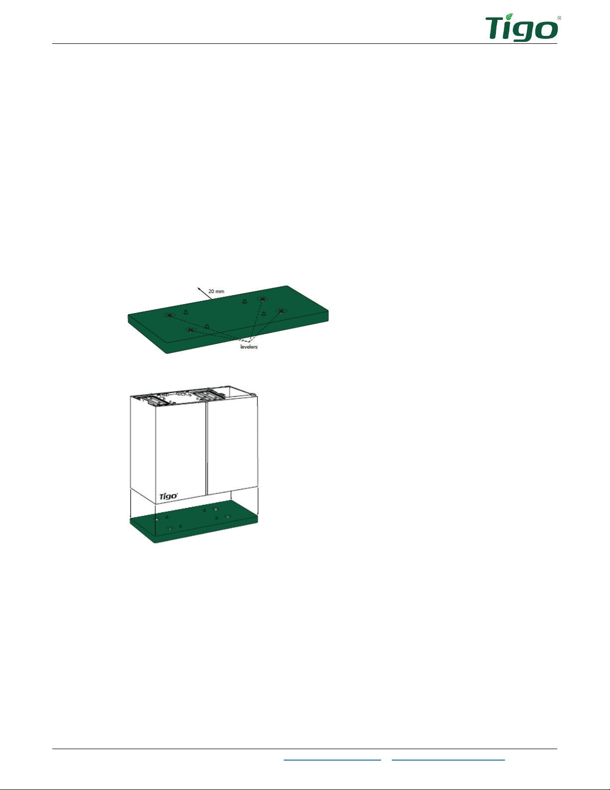
To position one or more batteries:
1. Place the battery base 20mm from the wall and adjust levelers if necessary.
2. Place a battery on the base.

Installation – Place Batteries
3. If installing a single battery, attach the battery bracket to the top of the battery and the
wall. Ensure 20mm clearance between the wall and the battery enclosure.
4. If installing an additional battery, use two M4 screws to secure it on the left and right
sides of the bottom battery.
5. If installing one or more batteries to the right of the main rack, install a base.
6. Install two cover brackets on the top-most battery, place the top cover on the battery,
and press down.

Installation – Assemble and Mount the System Bracket
Assemble and Mount the System Bracket
The single-phase system bracket includes two vertical wall-mounting plates and two horizontal
component-mounting plates found in the inverter and link packages:
•EI Inverter package: horizontal inverter plate
•EI Link package: vertical link plate, horizontal link plate, and vertical BMS plate (single-
phase only)
To assemble the system bracket, use M5 screws found in the inverter accessory box:
1. Attach the horizontal inverter plate onto the vertical link plate. The vertical plate will rest
against the wall.
2. Attach the link horizontal plate onto the vertical link plate.
3. Single phase: Attach the link horizontal plate onto the vertical BMS plate.

Installation – Assemble and Mount the System Bracket
To mount the system bracket:
1. Single phase: Attach the system bracket to the already-installed battery bracket.
2. Mount the system bracket to the wall using appropriate mounting hardware at the
locations shown in the diagram. Ensure the vertical plates are plumb and the brackets
are level.
Three phase: Mount the system bracket so that the bottom of the horizontal link plate
has at least 455mm clearance above the floor or top of the battery.

Installation – Install the Inverter
Install the Inverter
The EI Inverter package includes:
•Inverter (single or three phase)
•Inverter horizontal mounting plate
•Wall anchor, washer, and lag bolt (3)
•M5 inner hex screw
•Waterproof RJ45 connectors (2 spares)
•RJ45 terminals (3, three phase only)
•Battery power cable connectors (2)
•Safety manual
•Quick Start Guide
To install the inverter, slide it onto the horizontal inverter plate and secure it using an M5
screw.

Installation – Install the Link
Install the Link
The single-phase EI Link package includes:
•Link module
•6mm ferrules (5)
•16mm ferrules (5)
•16mm ring terminal
•Flange nuts (4)
•Wall anchor, washer, and lag bolt (2)
•Earthing wire
•Quick Start Guide
•Horizontal link mounting plate
•Vertical link mounting plate
•Vertical BMS plate
•Waterproof RJ45 connector (spare) 3
•CCA antenna
•Tigo Access Point (TAP)
The three-phase EI Link package includes:
•Link module
•Vertical link mounting plate
•Horizontal link mounting plate
•6mm ferrules (8)
•Flange nuts (2)
•Wall anchor, washer, and lag bolt (2)
•16mm earthing terminal
•16mm ferrules (10)
•Rubber plugs (2)
•Tigo Access Point (TAP)
•Waterproof RJ45 connector (3)
•CCA antenna
•Quick Start Guide

Installation – Install the Link
To install the link and connect it to the inverter:
1. Crimp ends of all unterminated conductors with ferrules and earthing terminals and
torque to 1.5Nm.
2. Slide the link onto the horizontal link plate and secure it using an M5 screw.
3. Connect the preinstalled inverter earthing cable to the link.
4. Connect the COM and CT cables to their respective connections on the bottom of the
inverter and the link.
This manual suits for next models
4
Table of contents
Other Tigo Inverter manuals

Tigo
Tigo EI User manual

Tigo
Tigo TSS-3PS User manual

Tigo
Tigo EI User manual

Tigo
Tigo TS4-A-O User manual

Tigo
Tigo TSI-3K1D User manual

Tigo
Tigo TS4-A-2F User manual

Tigo
Tigo TS4-F User manual

Tigo
Tigo TSI-6K3DTSI-10K3D User manual

Tigo
Tigo ENERGY MODULE MAXIMIZER ES Series User guide

Tigo
Tigo EI ATS 200A User manual


