4. Pre-commissioning checklist
Check Item Acceptance Criteria
Inverter installation The Inverter, EI Link, BMS, and Batteries (if applicable) are correctly installed and securely mounted.
Cable layout Conduit/Cables and conductors are routed properly.
Cable connections The AC output conductors, DC input conductors, and communications cables are labeled and connected correctly and securely.
Cable ties Cable ties are secured evenly with no sharp protrusions.
Grounding Ground conductors are connected correctly fastened.
Disconnect switches The inverter’s DC disconnect switch and all external disconnect switches connecting to the EI Inverter are in the OFF position.
Wirebox cleanliness The wirebox is left clean and tidy.
Installation environment Ensure surrounding area meets spacing requirements.
5. Commissioning
CAUTION - For personal safety always wear appropriate PPE.
6. Your Customer Service Contact
!
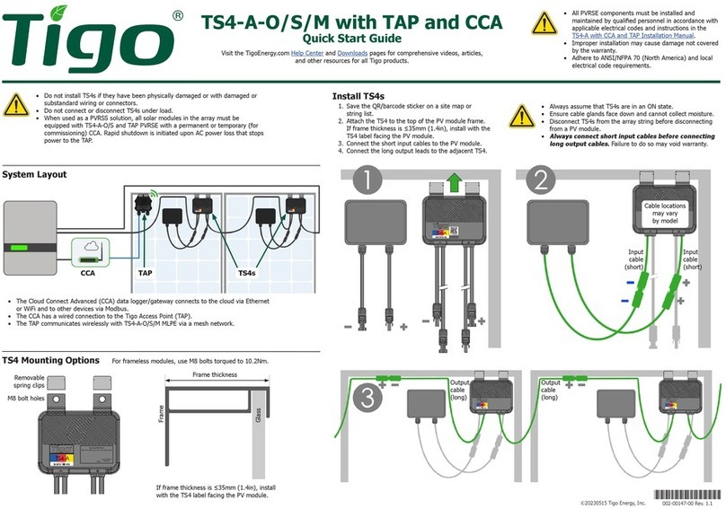
The steps to turn on the inverter are as follows:
1. Before powering on, ensure the grid voltage is within the specication of the inverter, otherwise damage may occur.
2. Verify COM cable between EI Link and inverter is connected.
3. Turn on the DC breaker the left of the BMS.
4. Press and hold the Power button next to the DC breaker from BMS to start the battery.
5. Turn on the PV switch at the EI Link.
6. Turn on the RCD and Grid(Inv) breaker in the EI Link.
7. Turn on the service disconnect between the grid and the Tigo EI Inverter.
8. Ensure the E-stop button (if used) is not in the de-pressed position.
9. Open the Tigo EI app to complete commissioning by making all required inverter and battery settings.
10. Once the Tigo EI commissioning is completed, press and hold the “Enter” button for 5s the right of the inverter LCD screen. Then inverter will be in normal
operation mode.
Tigo Energy Italy
Srl Via Calamandrei 36 52025
Montevarchi Tuscany, Italy
Americas: +1 408 402 0802
International: 00800 2255 8446
https://support.tigoenergy.com/
3.1.4 Preinstalled Grounding Wire
1. Connect the EI Link and EI Inverter grounding terminals with a
properly sized grounding cable.
2. Connect the EI Link and BMS grounding terminals with a
properly sized (installer made) grounding cable.(Future step)
3. Use a hex key to tighten all grounding lugs to 1.5NM.
3.1.5 Connect battery power cables
1. Remove the BAT caps on the
bottom of the inverter
2. Connect one end of negative and
positive Battery Power Cables
(found in BMS box) to the BMS
BAT- and BAT+ ports.
3. Connect the other end of the
negative and positive Battery Power
Cables to the EI Inverter BAT- and
BAT+
EI Inverter
EI Link
Grounding Cable
To BMS
CAN1 CAN2 DRM OFF
COM BMS CT
BAT
CAN1 CAN2 DRM OFF
COM BMS CT
BAT
Three Phase EI Inverter
Quick Start Guide - TSI-6K3D/TSI-10K3D/TSI-15K3D
Pg 3 of 4
Note: the EI Inverter grounding wire is preinstalled. It will
be connected to the EI Link in a future step of that QSG.
Note: The Battery charging power cables are located
in the BMS Accessory Kit.
PN: 002-00108-00 | REV 2.0 | Oct. 20, 2022
