Tigo TSI-7.6K-US User manual

Inverter
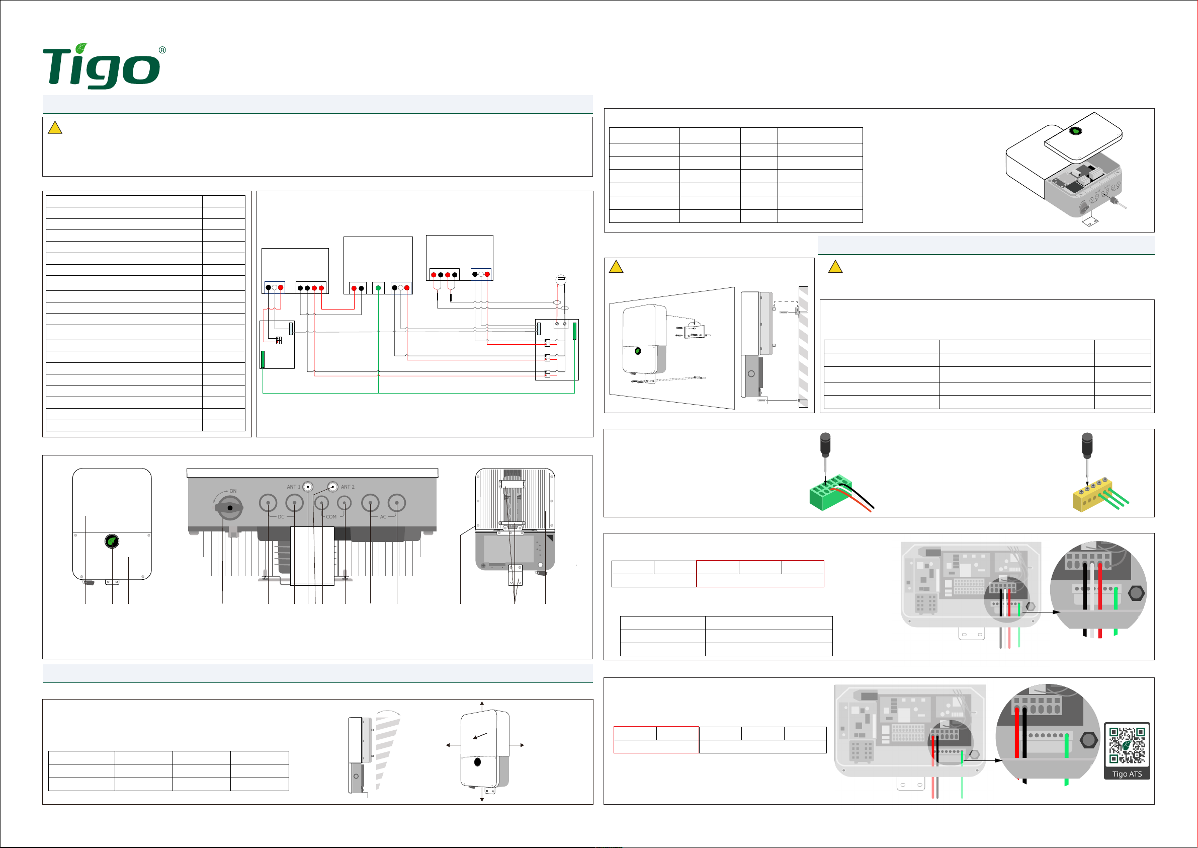
EI Inverter
!
1. General Information - Specications
2. Installation
ATTENTION - READ FIRST
!CAUTION - Use appropriate hardware for
the mounting surface !CAUTION - Check that all Disconnect switches are OFF
before wiring. For personal safety, do not operate with
electricity and always wear appropriate PPE.
1.1 Package Contents
1.3 EI Inverter Overview
1. Front panel
2. LED indicators
3. Wiring box cover
4. DC disconnect switch
5. PV input
6. Battery input
7. WiFi antenna port
8. Cellular antenna port
9. TAP /M et er /R SD input
10. Battery com input
11. Backup output
12. AC grid output
13. External Grounding point
14. Moun ti ng b rac ke t
15 . He at s in k
1 2 3 567 9 10 11 12 13 14 15
8
4
2.1 Installation requirements
1.2 AC Wiring Diagram
2.3 Mounting
3.1 Wire schedule/preparation
2.2 Prepare conduit openings
3.2 Connections
3.3 Inverter output connection - GRID
3.4 Backup output connection - Battery systems only
L2 L1 L1 N L2
Backup Grid
L2 L1 L1 N L2
Backup Grid
Inverter Model Over current rating
TSI-7.6K-US 40A (bi-directional)
TSI-11.4K-US 60A (bi-directional)
1 . Determine which inputs/ports will need to be opened 2. Remove wire box cover (3)
using 3/16” (5mm) screwdriver
3. With a hole saw, CAREFULLY
open the conduit drill guide for the
necessary openings.
Quick Start Guide - TSI-7.6/11.4K-US
Pg 1 of 4
Item Quantity
EI Inverter 1
Quick Start Guide 1
Mounting Bracket 1
Tigo Access Point (TAP) 1
Rapid Shutdown label 1
E-stop button 1
DC wire ferrules 7.6kW: 16
11.4kW: 20
AC wire ferrules 5
RS485 3-pin connector (meter) 1
Grounding ring terminal 1
Hex-head Self tapping screws (inverter
mounting) 5
Philips-head screw (E-stop mounting) 4
White wall anchors (inverter) 5
Green wall anchors (e-stop) 4
WiFi antenna 1
Cellular antenna (only in cell-enabled models) 1
¾” conduit hole plug, with nut 1
1” conduit hole plug 2
1” conduit hole plug nut 2
Item W (inch/mm) H (inch/mm) D (inch/mm)
TSI-7.6K-US 15.75/400 22.4/570 7/170
TSI-11.4K-US 15.75/400 25.2/638 7.4/187
Use Type Size
Equipment Grounding Conductors Yellow-green jacketed or solid bare copper 10 - 8 AWG
AC output conductors
(BACKUP/GRID) Multi-color jacket, copper 8 - 6 AWG
PV Input conductors Red/Black Photovoltaic Wire (ex: PV1-F) 10 - 8 AWG
Battery input conductors Red/Black Photovoltaic Wire (ex: PV1-F) 12 - 8 AWG
≤15°
≥12”≥12”
≥12”
≥12”
≥12”
References in
Guides
Label on
Inverter
# on
diagram Drill / if installing
PV input DC (left side) 5 Yes
Battery input DC (right side) 6 Yes / battery
Comm COM (left side) 9 Yes / TAP or meter
Comm COM (right side) 10 Yes / battery
Backup output AC (left side) 11 Yes / ATS
AC grid output AC (right side) 12 Yes
3. Electrical Connections
NG
Inv Grid Inv
L1 L1 L2 L2
Backup
Panel
L1 N L2
ATS
Input
Inv Grid Inv
L1 L1 L2 L2
Backup
Panel
L1 N L2
ATS
Input
EI Inverter
ATS
L2 L1
ACGrid
L1 N L2
EGC
EI Inverter
ATS
L2 L1
ACGrid
L1 N L2
EGC
CT L1 CT L2
+
ACGrid
L1 N L2
EnergyMeter
-+ -
CT L1 CT L2
+
ACGrid
L1 N L2
EnergyMeter
-+ -
N
G
Grid
Meter
Grid
Meter
Backup Panel
Main Panel
1. This document is for quick guidance only. For details, please refer to the Energy Intelligence (EI) Inverter Installation & Operations Manual.
2. Damage caused by failure to follow the contents of the EI Inverter Installation & Operations Manual is not covered by the warranty.
3. Before installing the system, check that the package contents are intact and complete against the packing list. If any damage is found or any component is
missing, contact your dealer.
1. Do NOT install the EI inverter in the direct sun, rain or
snow
2. If installing more than one inverter, refer to the EI Inverter
Installation & Operations Manual for clearances
1. To prepare the DC conductors (PV+, PV- and BAT), strip 5/8”/16mm of the DC connector’s
jacket and crimp on the DC wire ferrule.
2. To prepare the AC conductors (GRID and BACKUP), strip 0.7”/18mm of the AC conductor’s
jacket and crimp on the AC wire ferrule.
3.2.1 Pressure Terminals
1. Insert 1/8” at blade screwdriver in the terminal
at a right angle to the terminal face. Press the
clamp open by tilting down.
2. Insert conductor into the terminal’s round
opening.
3. Remove screwdriver to release the clamp and
secure the conductor.
4. Gently tug conductor to ensure it is secure.
3.2.2 Screw Terminals
1. Insert equipment grounding
conductor (EGC) into the grounding
busbar.
2. Use an #2 philips screwdriver to
tighten the set screw and securing
the EGC.
3. Gently tug the conductor to ensure
it is secure.
1. Install the AC conduit to the AC grid output opening (12). Use appropriate
conduit ttings and bond where necessary. Run AC grid conductors.
2. Terminate the AC grid conductors to the appropriate terminal.
3. Connect the AC EGC to the grounding busbar.
4. Terminate the opposite end of the inverter output conductors at the main
service panel with the appropriately sized OCPD.
1. Install the AC conduit to the AC grid output opening (11).
Use appropriate conduit ttings and bond where necessary.
Run AC backup conductors.
2. Terminate the AC backup conductors to the appropriate
terminal.
3. Connect the AC EGC to the grounding busbar.
4. The opposite end of the Backup conductors terminate at the
ATS. To complete the ATS connections at this time, refer to
the ATS manual. Ver. Dec. 20, 2021
PN: 002-00078-00

EI Inverter
Quick Start Guide - TSI-7.6/11.4K-US
Pg 2 of 4
4. Communications connections
Scan here for the TS4 downloads
3.5 TS4 Installation
CAUTION - To prevent damage to the TS4,
always connect PV modules to the TS4 input
before connecting output conductors in the
string. Refer to the TS4 Installation Manuals
for the TS4 installation requirements.
!
CAUTION - Do not reverse positive and
negative of the battery input terminal.
!
CAUTION -Do not cut or extend CT wires. The CTs wires are 80”, plan accordingly.
!
3.6 PV connections
1 2 341234 + -
PV+ PV- BAT
RJ45
Pin
Wire color
Signal denition Function
T568B T568A
1 White/Orange White/Green Enable+ Wake-up
2 Orange Green Enable-
3 White/Green White/Orange CANL CAN Communication
4 Blue Blue CANH
5 White/Blue White/Blue GND GND
6 Green Orange Received NC
7 White/Brown White/Brown RS485B RS485 communication
8 Brown Brown RS485A
3.7 Battery connections - Battery systems only
1 2 341234 + -
PV+ PV- BAT
4.1 Tigo Access Point (TAP) installation
4.2 Battery communications - Battery systems only
4.3 Meter connections
1. Using a cable cutter/stripper, remove the 1/2in of the external
insulation/jacket from the CAT5/6 cable, exposing the 4 twisted
pairs of wire.
2. Untwist approximately 1/2in of the end of the wires and insert the
eight wires into the an RJ45 connector. Choose either T568A or
T568B standard for wiring – stay consistent.
3. Crimp the connector with the appropriate crimping tool.
4. Install the battery communications conduit to the COM battery
input opening (10), use appropriate conduit ttings and bond
where necessary. Run battery CAT5/6 cable.
5. Connect the communications cable from the battery to the RJ45
port in the inverter wire box.
1. Install the meter communications conduit from the main service panel (location of the meter) to the inverter’s TAP/meter COM input (9) and run the RS485
(3 wires needed). Additional wires may need to share this raceway (E-stop, TAP). Plan the conduit layout with this in mind.
2. Remove the cable’s external insulation using a crimping tool or cable cutter.
3. Insert the RS485 communication cable into the 4-pin connector. Note – the farthest right terminal on the male adaptor is not used.
4. Plug connector into the meter communications terminal.
5. Clamp CT’s around the corresponding grid input conductors (L1, L2) ensuring that the arrow is pointing away from the grid.
6. Connect the meter’s L1, L2, N to the main service panel, using 15A circuit breaker on L1, L2.
1. Install the Battery conduit to the DC Battery input
opening (6), use appropriate conduit ttings and
bond where necessary. Run the battery conductors.
2. Terminate the battery conductors to the appropriate
terminal.
3. Connect the battery EGC to the grounding busbar.
1. Install the TAP within the array boundary.
2. Run the RS485 or CAT5/6 cable from the TAP to the inverter.
3. Terminate the TAP communications wire in the inverter at the 4-
pin connector. From bottom to top: -, +, B, A. 1. Carefully screw WiFi antenna in the WiFi antenna port, ANT1 (7).
2. If the inverter includes the cellular function, carefully screw the
Cellular antenna in the Cellular antenna port, ANT2 (8).
1. Install the PV conduit to the DC PV input opening (5), use
appropriate conduit ttings and bond where necessary. Run the
PV string conductors.
2. Terminate the PV strings to the appropriate terminal.
3. Connect the PV EGC to the grounding busbar.
1. Install the TS4 module-level power electronics (MLPE) on
the back of the PV modules.
2. Connect the PV module to the TS4 input conductors.
3. Connect the TS4 output conductors together to form a
string.
4. If using the TS4-A-F/TS4-A-2F, no additional steps are
necessary.
5. Remove each barcode sticker from the TS4-A-O and place
in the grid on the last page of this document in the position
and orientation of the module as it is in the array. If using
the TS4-A-F/TS4-A-2F, this step is not necessary.
NOTE: The TSI-7.6K-US has 3 MPPTs, the TSI-11.4K-US has 4
MPPTs.
NOTE: The TAP is a required to enable module-level monitoring,
and rapid shutdown functionality in the TS4-A-O.
NOTE: All EI Inverters come with the WiFi antenna. The cellular
antenna is included for inverters which include this communication.
NOTE: This connection is required for the operation of the EI Battery.
12345678 12345678
T568B T568A
RJ-45 Male Plug
NG
EI Inverter
ATS
L2 L1
ACGrid
L1 N L2
EGC
CT L1 CT L2
+
ACGrid
L1 N L2
EnergyMeter
-+ -
Grid
Meter
Grid
Meter
Main panel
A G B
RS-485
A+ B- G
4.4 Antenna connections
Ver. Dec. 20, 2021
PN: 002-00078-00

EI Inverter
Quick Start Guide - TSI-7.6/11.4K-US
Pg 3 of 4
5. Pre-commissioning checklist
6. Commissioning
CAUTION - For personal safety always wear appropriate PPE.
This Rapid Shutdown (RSD) initiation switch is intended to act as the National
Electric Code (NEC) required activation device for rapid shutdown systems. The
RSD switch is a normally closed (NC) contact. When the button is pushed, the
state of the initiation switch is open and the system’s PV array enters rapid
shutdown in which all conductors from the modules to the Tigo EI inverter are
reduced to less than 30VDC within 30 seconds. This solution complies with the
2017 and 2020 NEC.
8.1 General Information
7. LED Status
TSI-7.6/11.4K-US inverters come with four LED indicators. On the front cover, from left to right, the indicators show POWER, Battery status, COM, and FAULT.
Check Item Acceptance Criteria
Inverter installation The inverter is installed correctly, securely and reliably.
Conduit/Cable layout Conduit/Cables and conductors are routed properly, and as requested by the customer.
Cable connections The AC output conductors, DC input conductors, and communications cables are labeled and connected correctly and securely.
Cable ties Cable ties are secured evenly with no sharp protrusions.
Grounding Ground conductors are connected correctly, securely and reliably.
Conduit connections All conduit attachments are sealed and bonded, when necessary.
Unused conduit openings Any unused conduit openings are tted with waterproof caps (provided) or left unopened.
Disconnect switches The inverter’s DC disconnect switch and all external disconnect switches connecting to the EI Inverter are in the OFF position.
Wirebox cleanliness The wirebox is left clean and tidy.
Installation environment An appropriate installation space had been chosen and the environment is left clean and accessible.
Symbol Function Color Status Action Description
POWER Green
ON Steady Feed in grid
Blink 3s on / 1s off DC ON / AC OFF
Blink 1s on / 3s off DC OFF / AC ON
Blink 0.5s on / 0.5s off Checking
Blink 2s on / 2s off Standby mode
COM
Green
ON Steady 4G/WiFi, local WiFi ok
Blink 0.5s on / 0.5s off Local WiFi connecting
Blink 1s on / 1s off 4G/WiFi failure, local WiFi ok
Blink 1s on / 3s off Local WiFi failure, 4G/WiFi ok
Blank Off Steady Communications failure
BAT Green
ON Steady Battery is in normal operation
Blink 1s on / 3s off Battery is in low power
Blink 0.5s on / 0.5s off Battery is in fault mode
FAULT Red
ON Steady with audible buzzer alarm Arc fault
Blink 1s on / 1s off Warning
ON Steady Fault
8. PVRSS initiation switch
CAUTION - Use appropriate hardware for the mounting surface.
!
8.3 Mounting the RSD initiation switch
CAUTION - Make sure the inverter is OFF. Pull up on the RSD button to ensure it is in the “normally close” position.
!
!
8.4 Wiring the RSD initiation switch
Items needed for the installation:
• Signal conductors (24V rated)
• Conduit and appropriate
weatherproof connectors
• Drill with 5mm bit
• Philips head screwdriver
• Installed EI Inverter
Included in the packaging for
this installation:
Item Quantity
Green plastic wall
anchor 4
Philips-head self-
tapping screws 4
8.2 Required for installation
Ver. Dec. 20, 2021
PN: 002-00078-00
9. Your Customer Service Contact
Tigo Energy, Inc.
655 Campbell Technology Pkwy
Campbell, CA 95008
T: +1 408 402 0802
https://support.tigoenergy.com/
1. Using a Philips head screwdriver, unscrew the 4 plastic screws of the assembled RSD
initiation switch to open the enclosure.
2. Use the base of the enclosure to mark 4 holes on the wall and drill the holes out. Insert
the wall anchors into the holes.
3. Align the holes of the RSD initiation switch base with the holes in the wall. Using a
Philips screwdriver, screw the self tapping screws through the enclosure base into the
wall anchors.
1. Install RSD switch conduit to the TAP/Meter/RDS COM input (9), use appropriate conduit ttings and bond where necessary. Run
the signal conductors.
2. Connect the conductors to the RSD switch as shown.
3. Reinstall the RSD initiation switch cover and tighten the plastic screws to secure.
4. Remove the 3-pin connector from terminal CN14 and remove the jumper across the pins.
5. Insert the conductors in the 3-pin conductor’s positions 1 and 3, as shown.
6. Replace the connector in the terminal CN13 and replace the inverter wirebox cover.
The steps to turn on the inverter are as follows:
1. Before powering on, please make sure all voltages and current are within the specication of the inverter, otherwise damage may occur.
2. Turn on the DC disconnect switch between the battery and the inverter.
3. Turn on the DC disconnect switch at the bottom of the Tigo EI Inverter.
4. Turn on the BAT switch located on the left side of the Tigo EI Battery.
5. Turn on the service disconnect between the grid and the Tigo EI Inverter.
6. Ensure the e-stop button (if used) is not in the de-pressed position.
7. Open the Tigo EI app to complete commissioning by making all required inverter and battery settings.
NOTE: The shutdown steps are the opposite to the order above.

EI Inverter
Quick Start Guide - TSI-7.6/11.4K-US
Pg 4 of 4
Examples:
Place TS4-A-O barcode stickers in the grid below per the system azimuth and layout for scanning into the EI App. Ver. Dec. 20, 2021
PN: 002-00078-00

Battery

EI Battery Storage
(1) Handle
(2) Battery enclosure
(3) Base
(4) Disconnect Switch
(5) DC Knockout
(6) Power Button
(7) Communications knockout
(8) Inverter connection wirebox
(9 ) Fr on t co ve r
(10) LED indicator
(11) Base front cover
(12) Battery expansion wirebox
(1 3) G EC /b on ding te rm in al
(1 4) M ou nt in g tabs
(1 5) H ea t si nk
Door locking clips
(behind front panel)
1 2 3 456 7 8 9 10 11 12 13 14 15
1. General Information - specication
Note – The battery module’s power terminals face the right side of the enclosure. Install top battery before bottom battery packs.
Three battery modules per enclosure: 1 on top, 2 on bottom.
2.5 Install the battery modules
2.4 Removing the cover
Quick Start Guide - TSB-10/20-US
Pg 1 of 3
ATTENTION: READ FIRST
!
WARNING – the door has a grounding wire and display cable attached to the interior. Use caution and detach wires before
attempting to remove the door.
!
CAUTION - Ensure 12” clearance around all sides. Use appropriate hardware for the mounting surface.
For personal safety always wear appropriate PPE.
!
1.1 Package Contents
1.2 EI battery enclosure overview
Item Quantity
Battery Enclosure 1
Quick Start Guide 1
Safety-lock screws 6
Sleeve anchors 2
Wire ferrules 4
2.1 System overview
Inverter – battery wiring connection.
All inverter connections are made on the left
side of the battery enclosure.
Battery expansion wiring connections.
All battery – battery connections are made on the right side of each battery.
2. Installation
BAT+
BAT-
COM
Left side
2.3 Mounting
1
1
3
3
2
2
1. This document is for quick guidance only. For details, please refer to the Energy Intelligence
(EI) Battery Storage Installation & Operations Manual.
2. Damage caused by failure to follow the contents of the EI Battery Storage Installation &
Operations Manual is not covered by the warranty.
3. Before installing the system check that the package contents are intact and complete against
the packing list. If any damage is found or any component is missing, contact your dealer.
1. Remove the bottom plate (11) and remove 3 screws from each side, 6 total. Unlatch the 2 front door locks from the bottom.
2. Tilt up and CAREFULLY swing door to the left, using caution to not pull ground or display wires.
3. Unscrew ground conductor and unplug display cable then set door aside.
1. The battery module serial numbers will be needed for the
commissioning. These are labeled on the module and the
box they shipped in.
2. Place the battery in the enclosure then slide the brackets
inward on each side of the battery and tighten the wingnut
to secure.
3. Repeat for batteries 2 and 3.
1. Rotate mounting tabs (14) 90° to face outward.
2. Mark holes for drilling. Drill 2” deep holes with an 8mm bit.
3. Insert anchor bolt sleeve. Position the battery enclosure mounting tabs anchor sleeve. Secure with washers and bolts.
2”
8 MM
≥12”
≥12”
≥12”
≥12”
BAT+
BAT-
COM
Primary
Primary - Left side Primary - Right side Secondary - Right side
Secondary
Top
Front

EI Battery Storage
Quick Start Guide - TSB-10/20-US
Pg 2 of 3
If an external bonding point or grounding electrode conductor is
required, these may be connected to right side of the enclosure
at the GEC/Bonding terminal. This is not required for the
operation of the equipment.
3.4 GEC/Bonding terminal
3.3 Battery expansion
Note – This section applies to systems with multiple battery enclosures. The battery expansion cables/conductors should not exceed 6ft-7in.
If installing only one enclosure, skip this step.
Note – In the next section, Wiring the EI
Battery – Battery expansion, a communication
cable is routed between the two enclosures. At
the second enclosure this cable will terminate
at the Link-in terminal of battery module 4
(upper module/enclosure 2).
Wiring the battery modules (Battery enclosure 2)
If installing a second EI Battery enclosure complete
the power,Link-In and Link-Out connections as
described in the previous section.
EI Battery enclosure 1
Remove the terminating cap from the CAN/COM
terminal in the Battery expansion wire box (12) and
insert it in the Link-in terminal of battery module 1
(upper module/enclosure 1).
EI Battery enclosure 2
The terminating cap is inserted in the CAN/COM
terminal in the Battery expansion wire box (12). Do not
remove this cap.
Note – IF INSTALLING ONLY ONE BATTERY ENCLOSURE, A terminating cap is required
in the CAN COM port in the battery expansion wirebox (12).
3.2 Wiring the lower batteries
!CAUTION – Do not reverse positive and negative of the battery input terminal.
Lower battery connections
1. Locate the cables labeled for the lower battery modules.
2. Connect provided lower inner battery link-out cable
(loose cable) to the lower inner battery terminal labeled
link-out.
3. Connect the opposite end of the lower inner battery
link-out cable from step 2 to the link-in terminal on the
lower outer battery.
4. Connect the lower inner battery link-in cable to the
lower inner battery link-in terminal.
5. Connect the lower inner battery + plug to the lower
inner battery red terminal labeled +.
6. Connect the lower inner battery - plug to the lower
inner battery black terminal labeled -.
7. Connect the lower outer battery + plug to the lower
outer battery red terminal labeled +.
8. Connect the lower outer battery - plug to the lower
outer battery black terminal labeled -.
9. Connect the outer lower battery link-out cable to the
link-out terminal on the lower outer battery.
Note – The battery conductors and communications cables are labeled and located
inside the enclosure. CAREFULLY cut cable ties and connect as shown. When properly
installed a click will be heard.
3. Connecting the Batteries
3.1 Wiring the upper battery
!CAUTION – Do not reverse positive and negative of the battery input terminal.
Upper battery connections
1. Locate the cables labeled for the upper battery module.
2. Connect the PCS cable to the battery terminal labeled PCS.
3. Connect the upper battery link-out cable to the battery port
labeled link-out.
4. Connect the + plug to the red battery terminal labeled +.
5. Connect the - plug to the black battery terminal labeled -.
upper
battery
lower
battery
3.3 Battery expansion - cont.
Note – This section applies to systems with multiple battery enclosures. The battery expansion cables/conductors should not exceed 6ft-7in.
If installing only one enclosure, skip this step.
1. Using a Philips screwdriver, loosen 2 captive screws on the expansion wirebox (12) on the right side of each enclosure.
2. Install 2 conduits from the right side of enclosure 1 to the right side of enclosure 2 for the DC conductors and communication cable. Use appropriate
conduit ttings to provide a water-tight seal.
3. Prepare 2 DC conductors 6AWG and route through the conduit and one CAT5/6 with RJ45 connectors on each end.
4. Connect BAT-Expansion + from enclosure 1 to BAT-Expansion + of enclosure 2.
5. Connection BAT-Expansion - from enclosure 1 to BAT-Expansion - of enclosure 2.
6. Connect CAN COM from enclosure 1 to CAN COM of enclosure 2.
Primary Secondary
CAN
COM
CAN
COM
CLICK
CLICK
CLICK
CLICK
CLICK
CLICK
Inner battery
Outer battery
BAT 1
Upper
Enclosure 1 Enclosure 2
BAT 2
Lower Inner
BAT 3
Lower Outer
Bottom
Top Upper BAT Link-out
Lower inner BAT Link-in
Lower outer BAT Link-out
Upper BAT Link-out
Lower inner BAT Link-in
Lower outer BAT Link-out
Terminating
Cap
Terminating
Cap
BAT 4
Upper
BAT 5
Lower Inner
BAT 6
Lower Outer
Bottom
Top
Lower inner BAT Link-out
Lower outer BAT Link-in
(12) (12)

EI Battery Storage
Quick Start Guide - TSB-10/20-US
Pg 3 of 3
Ver. Oct. 25, 2021
PN: 002-00083-00
5. Pre-power checklist
6. Powering on the battery storage system
7. LED indicators
LED lights are displayed as follows in TSB-10/20-US different states:
A: Middle indicator (indicate status)
B: Ring indicator (indicate battery power)
B4
B1
A
B3 B2
Number Status LED light display
1Standby state Center leaf; ashing green (0.5 seconds on and 2 seconds off)
indicates the standby state. Ring indicator-refer to Discharge state.
2Charge state
Center leaf; green light is on. Ring indicator indicates
1. Power≤25%, LED B1 ashes, LED B2/3/4 are off;
2. Power≤50%, LED B1 is on, LED B2 ashes, LED B3/4 are off;
3. Power≤75%, LED B1/2 are on, LED B3 ashes, LED B4 is off;
4. Power>75%, LED B1/2/3 are on, LED B4 ashes.
3Discharge state
Center leaf green light is on. Ring indicator indicates
1. Power≤25%, LED B1 is on, LED B2/3/4 are off;
2. Power≤50%, LED B1/2 are on, LED B3/4 are off;
3. Power≤75%, LED B1/2/3 are on, LED B4 are off;
4. Power>75%, LED B1/2/3/4 are on.
4Alarm state Center leaf; green light ashes (0.5 seconds on and 0.5
seconds off, 0.5 seconds on and 2 seconds off). Ring indicator-refer to Discharge state.
5Fault state Center leaf; red light ashes (1 second on and 1 second
off). Ring indicator-refer to Discharge state.
6Upgrade state Center leaf; yellow light ashes(1 second on and 1 second off) indicates the upgrade state. Ring
indicator-refer to number 1.
7Manual forced power
on
Center leaf; green light ashing (0.1 seconds on and 0.1
seconds off) . Ring indicator-refer to Discharge state.
8Manual forced
shutdown
Center leaf; red light ashing (0.1 seconds on and 0.1 seconds off). Ring indicator-refer to Discharge
state.
Note – All other components of the EI Battery Storage system, including the energy meter must be installed for the system to operate.
!CAUTION – For personal safety always wear appropriate PPE.
8. Forced start/shutdown
Check Item Acceptance Criteria
Communications cable The communications cable is labeled and properly connected to both the inverter and battery communications terminals.
Battery power conductors The battery power conductors are labeled and properly connected to the inverter and battery terminals.
GEC/bonding If required, the GEC/bonding conductor is properly connected.
Expansion wiring If multiple batteries installed, BAT-Expansion+/BAT-Expansion- conductors and communications cable are properly connected.
Conduit connections All conduit attachments are sealed and bonded, when necessary.
Unused conduit openings Any unused conduit openings are tted with waterproof caps (provided) or left unopened.
Disconnect switches The BAT-switch and all other switches connecting to the EI Battery are OFF.
Installation environment An appropriate installation space had been chosen and the environment is left clean and accessible.
9. Your Customer Service Contact
Tigo Energy, Inc.
655 Campbell Technology Pkwy
Campbell, CA 95008
T: +1 408 402 0802
https://support.tigoenergy.com/
1. Turn ON the BAT-switch in the Inverter connections wirebox (8).
2. If multiple batteries installed, turn on the BAT-Expansion breaker in the Battery expansion wirebox (12). Otherwise, skip this step.
3. Turn on the inverter, while waiting 10 seconds for the inverter to send the wake-up signal observe the LED indicator of the battery enclosure. Conrm the
battery system enters the discharge state (center leaf is lit).
4. The battery storage system has been successfully started.
To force start or shutdown the EI Battery:
1. Using a Philips screwdriver, remove the screws from the cover of
the forced start power button (6).
2. Press and hold the button for 10 seconds until:
1. OFF: The center leaf changes from green to red and begins
ashing quickly (0.1s on/off)
2. ON: The center leaf begins ashing green (0.1s on/off).
3. After the forced start/shutdown is successful, reinstall the cover.
8. Forced start/shutdown
4. Connecting the inverter
Note – This section corresponds to section 3.7 and 4.2 in the EI Inverter Quick Start Guide.
Reference that document by scanning the QR code.
!CAUTION – Risk of electric shock! Ensure the inverter and battery cabinet are completely powered off when these
steps take place. Make sure to connect the battery inverter first and then connect the communications cable to the
inverter.
1 2
3
4
1. Loosen the two captive screws of the battery enclosure’s inverter connection wirebox (8).
2. Remove the two waterproof knockouts (5), (7) at the bottom of the left side of the enclosure. Connect two conduits from the battery
enclosure to the inverter. Use appropriate water-tight ttings.
3. Prepare two conductors, 10-8AWG with wire ferrules and route through the conduit.
4. Verify the BAT-switch is in the OFF position, and connect the conductors as follows:
1. Insert the battery conductors into the terminals of BAT+ and BAT- (EI Inverter Quick Start Guide 3.7).
2. Insert the RJ45-CAT5/6 communications cable into the INV terminal (EI Inverter Quick Start Guide 4.2).
5. Once complete, replace the wirebox covers and the enclosure cover by reversing the steps of section 2.4

50A ATS

EI Automatic Transfer Switch (ATS)
2. Installation
1. General Information
3. Electrical connections
Conductor Schedule
Conductor Quantity Type Size
Grid 2
Min. 90°C rated, insulated, copper, solid or
stranded (not ne stranded)
L1, L2: 10-6AWG
Inv Backup 2 L1, L2: 10-6AWG
Load 3 L1, L2, N: 10-6AWG
Load EGC 1
Min. 90°C rated, insulated or bare, copper, solid
or stranded (not ne stranded) EGC: 6AWGGrid EGC 1
Inv backup EGC 1
Quick Start Guide - TSS-50-US
Pg 1 of 2
1. This document is for quick guidance only. For details, please refer to the Energy Intelligence (EI) ATS Installation & Operations Manual.
2. Damage caused by failure to follow the contents of the EI ATS Installation & Operations Manual is not covered by the warranty.
3. Before installing the system, check that the package contents are intact and complete against the packing list. If any damage is found or any component
is missing, contact your dealer.
1.4 EI ATS Overview
1. Mounting bracket
2. 1 1/4" knockout
3. Front door
4. Door locks
5. 1 1/4" knockout
6. 1” backup load knockout
7. 1” inverter knockout
8. 1” grid knockout
3 4 5 6 7 81 2
!ATTENTION – READ FIRST
!CAUTION – Use tools with insulated handles. Always wear
appropriate PPE.
!CAUTION - Use appropriate hardware
for the mounting surface
1.1 Package Contents
2.1 Mounting
1.2 Required Tools
3.1 Wire schedule/preparation
1.3 AC wiring diagram
Item Quantity
TSS-50-US ATS 1 Box
Quick Start Guide 1 Box
Sleeve anchors 3 Bag
Mounting screws 2 Bag
O-type terminal 3 Bag
Wire ferrules 8 Bag
Keys 2 Bag
Mounting bracket 1 Box
Item
Wire cutter/crimp tool
Screwdriver
Rubber mallet/hammer
Drill
Level
1. Reserve at least 12” on all sides of the ATS.
2. Use a level and the mounting bracket (1) to
mark the mounting holes. Drill out mounting
holes to 1.6” (40mm) depth.
3. Place the sleeve anchor in each hole, tap with
the mallet/hammer. Place mounting bracket
aligned with the anchors exposed through the
screw holes and use the 3 mounting screws to
attach to the wall.
4. Conrm bracket is level and screws are tight
then lift ATS on to the mounting bracket.
5. To open the door, insert key into top lock, turn
90° counterclockwise, then repeat on bottom
lock.
!CAUTION - Check that all Disconnect switches are OFF before wiring. For personal safety, do not operate with electricity and
always wear appropriate PPE.
1. To prepare the AC conductors (L1, L2, N), use the wire cutters to strip 15mm of insulation from one side of the conductor and crimp the wire ferrule to the
end of the conductor.
2. To prepare the ground conductors, strip 7mm of insulation (if using insulated conductors) from one side of the conductor and crimp the O-type terminal to
the end.
1 2
3
45
≥12”
≥12”
≥12”
≥12”
NG
Inv Grid Inv
L1 L1 L2 L2
Backup
Panel
L1 N L2
ATS
Input
Inv Grid Inv
L1 L1 L2 L2
Backup
Panel
L1 N L2
ATS
Input
EI Inverter
ATS
L2 L1
ACGrid
L1 N L2
EGC
EI Inverter
ATS
L2 L1
ACGrid
L1 N L2
EGC
CT L1 CT L2
+
ACGrid
L1 N L2
EnergyMeter
-+ -
CT L1 CT L2
+
ACGrid
L1 N L2
EnergyMeter
-+ -
N
G
Grid
Meter
Grid
Meter
BackupPanel
Main Panel

Ver. Oct. 25, 2021
PN: 002-00086-00
Tigo Energy, Inc.
655 Campbell Technology Pkwy
Campbell, CA 95008
T: +1 408 402 0802
https://support.tigoenergy.com/
7. Your Customer Service Contact
5. Commissioning
After completing the Pre-power checklist, close the cover.
If the battery, inverter, backup load panel installations are already complete, the system may now be turned on for operation. Follow the EI Inverter’s
Commissioning instructions (Section 6) to commission the system.
Keep the instruction manual and keys nearby.
EI Automatic Transfer Switch (ATS)
Quick Start Guide - TSS-50-US
Pg2 of 2
4. Pre-power checklist
Check Item Acceptance Criteria
ATS installation The ATS is installed correctly, securely and reliably.
Conduit/Cable layout Conduit/cables and conductors are routed properly, and as requested by the customer.
Cable connections The AC output conductors, DC input conductors, and communications cables are labeled and connected correctly and securely.
Cable ties Cable ties are secured evenly with no sharp protrusions.
Grounding Ground conductors are connected correctly, securely and reliably.
Conduit connections All conduit attachments are sealed and bonded, when necessary.
Unused conduit openings Any unused conduit openings are tted with waterproof caps or left unopened.
Disconnect switches All external disconnect switches connecting to the ATS are in the OFF position.
Wirebox cleanliness The wirebox is left clean and tidy.
Installation environment An appropriate installation space had been chosen and the environment is left clean and accessible.
Issue Check
In grid-on operation the ATS does not
switch over when there is loss of grid.
1. Turn OFF the EI Inverter and the grid.
2. Open the ATS door and check the grid and INV conductors are properly connected to the correct terminals.
3. If issues persist, please contact Tigo Customer Service team.
Backup load panel has no power.
1. Turn OFF the EI Inverter and the grid.
2. Open the ATS door and check the control line, the INV and BACKUP conductors are properly connected to the correct
terminals.
3. If issues persist, please contact Tigo Customer Service team.
!CAUTION – For personal safety always wear appropriate PPE.
6. Troubleshooting
!
CAUTION - Two control lines are terminated to positions
3 and 5 of the contactor. These are necessary for the
operation of the ATS. DO NOT REMOVE.
3.2 Inverter connections
1. Use the screwdriver to loosen screws in positions R2 and R8 at the
contactor’s INV inputs.
2. Insert L1 and L2 of the INV backup conductors into the INV input
terminals of R2 and R8.
3. Tighten to 2.5Nm.
4. Use the screwdriver to secure the inverter-backup EGC to the
grounding bus bar.
Note – Refer to section 3.4 Backup output connections in the EI
Inverter quick start guide for the connection of these conductors
in the inverter.
3.3 Grid connections
1. Use the screwdriver to loosen screws in positions 4and 6at the
contactor’s GRID inputs.
2. Insert L1 and L2 of the GRID conductors into the GRID input
terminals of 4and 6.
3. Tighten to 2.5Nm.
4. Use screwdriver to secure the GRID EGC to the grounding bus bar.
Note – The opposite end of the GRID conductors is fed from the
main service panel by a 50A circuit breaker.
3.4 Backup connections
1. Use the screwdriver to loosen the three screws on the BACKUP
terminals.
2. Insert L1, L2, and N of the BACKUP load conductors into the L1,L2,
and N BACKUP terminals.
3. Tighten to 3.5Nm.
4. Use screwdriver to secure the BACKUP EGC to the grounding bus
bar.
Note – The opposite end of the BACKUP load conductors feed
the subpanel dedicated to backup loads.
IN V
INV
IN V
IN V

200A ATS v1

EI Automatic Transfer Switch (ATS)
2. Installation
1. General Information
3. Electrical connections
Conductor Schedule
Conductor Qty Type Size
Grid 4
Min. 90°C rated, insulated
(or bare-EGC conductors),
copper, solid or stranded
(not ne stranded)
L1, L2, N: 4-4/0 AWG,
EGC: 6-1/0 AWG
Load 4 L1, L2, N: 1/0-4/0 AWG,
EGC: 6-1/0 AWG
Inverter 4 L1, L2, N: 8-6 AWG,
EGC: 8 AWG
Communications 1 RS485 shielded, twisted
pair (2-wire) 24 AWG
Quick Start Guide - TSS-200-US
Pg 1 of 3
1. This document is for quick guidance only. For details, please refer to the Energy Intelligence (EI) ATS Installation & Operations Manual.
2. Damage caused by failure to follow the contents of the EI ATS Installation & Operations Manual is not covered by the warranty.
3. Before installing the system, check that the package contents are intact and complete against the packing list. If any damage is found or any component
is missing, contact your dealer.
1.4 EI ATS Enclosure Overview
1. Status display
2. 1¼" Inverter knockouts
3. 2½" Load knockout
4. 2½" Grid knockout
5. 1¼" Communication knockout
6. 1¼" unassigned knockout
7. 1¼" Generator knockouts
8. Heat sink
!
!
ATTENTION – READ FIRST
!CAUTION – Use tools with insulated handles. Always wear appropriate PPE.
Although the Tigo ATS comes with
mounting hardware, use the appropriate
hardware for the mounting surface.
1.1 Package Contents
2.1 Mounting & opening the ATS
1.2 Required Tools
3.1 Electrical connections overview & conductor schedule
1.3 System wiring diagram
Item Quantity
TSS-200-US ATS 1
Mounting bracket 1
Quick Start Guide 1
Sleeve anchors 2
M6 Mounting screws 2
M5 Security screws 2
3-pin Connector 1
6-pin Connector 1
Item Use
Wire cutter/crimp tool Wiring the ATS
Philips Screwdriver Wiring terminals
Rubber mallet/hammer Mounting
Drill Mounting
Level Mounting
2.5mm-8mm Allen keys Cover/Security Bracket/Wire Terminals
1. Reserve at least 12” on all sides of the ATS. Install
vertically or tilted back no more than 15 degrees.
2. Use a level and the mounting bracket to mark the
mounting holes.
3. Drill out mounting holes to 1.7” (45mm) depth.
4. Place the sleeve anchor in each hole, tap with the mallet/
hammer. Place mounting bracket aligned with the anchors
exposed through the screw holes and use the mounting
screws to attach to the wall.
5. Conrm bracket is level and screws are tight then lift ATS
on to the mounting bracket.
6. Insert security screws into each side of the bracket,
fastening the bracket to the ATS with a 4mm Allen key.
7. Remove the caps covering the Allen head screws on the
front cover. Using an 5mm Allen key, loosen the Allen
screws and remove the cover.
!CAUTION - Check that all Disconnect switches are OFF before wiring. For personal safety, do not operate with electricity and
always wear appropriate PPE.
1 3
-
4
5 6
ATS
Communications
Key
Power
Main Panel
EI Battery EI Battery
Whole Home
Load
EI Inverter
TS4 MLPE
TAP
(TS4-A-O
systems only)
C
O
M
G
E
N
E
R
A
T
O
R
I
N
V
3
I
N
V
3
I
N
V
1
LOAD GRID
1
2
5 6 7
3 4
8
2 2
Inverter
communications
terminals
Grid terminal
L1 L1L2 L2
Load terminals
Neutral terminals
Ground terminals
Inverter
terminals
Neutral
terminals
Note – (3) additional 2½” knockouts
available on back (2) and side (1)

1. Run appropriately sized conduit from the inverter to an Inv knockout (2).
Use appropriate conduit ttings to ensure a water-tight seal. Route the
appropriate conductors from the inverter to the ATS.
2. Strip 10mm of insulation from the end of the Neutral and EGC of the
Inverter conductors. Insert into the Neutral and Ground busbars
respectively. Torque to 16.6ft-lbs (22.5 Nm).
3. Strip 10mm of insulation from the end of L1 and L2 of the Inverter
conductors. Insert into the Inverter’s breaker terminals. Torque to 1.5ft-lbs
(2 Nm).
!Do not wire until COMMUNICATIONS have been
completed.
3.5 Inverter power connections
EI Automatic Transfer Switch (ATS)
Quick Start Guide - TSS-200-US
Pg 2 of 3
3.2 Grid connections
3.3 Load connections
1. Run appropriately sized conduit to the Load knockout (3). Use
appropriate conduit ttings to ensure a water-tight seal and run the
Grid conductors.
2. Strip 10mm of insulation from the end of the Neutral and Ground
conductors and terminate at the neutral and ground bus bars with
16.6ft-lbs (22.5Nm).
3. Strip 10mm of insulation from the end of the L1 and L2 Load
conductors and terminate at the Load Terminals with 16.6ft-lbs
(22.5Nm).
Note – This connection feeds all power sources to the main load
panel to the home.
!
Check that the Grid disconnects/breakers, if
present, are in the OFF position before wiring the
ATS.
!The COMMUNICATIONS cable must be connected before
the INVERTER power connections.
3.4 Inverter communications connections
1. Run appropriately sized conduit from the inverter to the Com knockout (5).
Use appropriate conduit ttings to ensure a water-tight seal. Route the
RS485 cable from the inverter to the ATS.
2. The top 6-pin connector in the ATS is used for inverter communications.
Only the center two pins are used. Connect the wires to positions 3and 4
at the ATS.
3. At the inverter, the RS485 cable connects to the 3-pin connector above the
DC inputs. Only pins 1and 3are used. Ensure pin 1at the inverter is
connected to pin 3at the ATS and pin 3at the inverter is connected to pin
4at the ATS.
1. Run appropriately sized conduit to the Grid knockout (4). Use
appropriate conduit ttings to ensure a water-tight seal and run the
Grid conductors.
2. Strip 10mm of insulation from the end of the Neutral and Ground
conductors and terminate at the neutral and ground bus bars with
16.6ft-lbs (22.5Nm).
3. Strip 10mm of insulation from the end of the L1 and L2 Grid
conductors and terminate at the Grid Terminals with 16.6ft-lbs
(22.5Nm).
Note – This connection feeds power to the ATS from the utility
grid. Direct connection to utility feeders or a line side may
require coordination with the local utility company.
11
1
2
3
4
5
6
2 3
CN8

Tigo Energy, Inc.
655 Campbell Technology Pkwy
Campbell, CA 95008
T: +1 408 402 0802
https://support.tigoenergy.com/
8. Your Customer Service Contact
Ver. 1 Apr. 15 2022
PN: 002-00094-00
6. Commissioning
!CAUTION – For personal safety always wear appropriate PPE.
If the battery, inverter, and grid installations/connections are complete, the system may now be turned on for operation.
1. Turn on the battery DC switch.
2. Turn on the PV DC Disconnect switch at the bottom of the inverter. Release the RSD button. If inverter does not turn on, press and hold the push button
from left of the battery to force start the inverter. Note – Inverter error light will be ashing red due to no grid is detected.
3. Turn on the inverter circuit breaker inside ATS.
4. Turn on the AC Disconnect from the grid.
5. Download our App and start commissioning process.
6. Note - The “battery” light on the ATS becomes solid green if the inverter sees the grid. If no error light on the inverter and ATS, proceed to step 7.
7. Close the ATS door and torque the Allen screws to 1.8ft-lbs (2.5Nm).
EI Automatic Transfer Switch (ATS)
Quick Start Guide - TSS-200-US
Pg 3 of 3
5. Pre-power checklist
Check Item Acceptance Criteria
ATS installation The ATS is installed correctly, securely and reliably.
Conduit/Cable layout Conduit/cables and conductors are routed properly, and as requested by the customer.
Cable connections The AC output conductors, DC input conductors, and communications cables are labeled and connected correctly and securely.
Grounding Ground conductors are connected correctly, securely and reliably.
Conduit connections All conduit attachments are sealed and bonded, when necessary.
Disconnect switches All external disconnect switches connecting to the ATS are in the OFF position.
Workmanship Cable ties are secured evenly, have no sharp edges, the wirebox and installation area are left clean and accessible.
4. LED Status
Symbol Function Color Status Action Description
Grid Green
ON N/A Grid power is ON
OFF N/A No Grid power
Communications Green
ON N/A Normal operation
OFF 0.5s on / 0.5s off Abnormal communications with the
inverter
System Status Green
ON N/A Normal operation (on-grid)
Flashing 1s on/off N/A Normal operation (off-grid)
Fault Red
ON 0.5s on / 0.5s off A Fault has occurred
OFF N/A Normal operation
Flashing 1s on/off 1s on / 3s off The connected loads are overloading
the available output power
Issue Check
In grid-on operation the ATS does not
switch over when there is loss of grid.
1. Turn OFF the EI Inverter and the grid.
2. Open the ATS door and check the grid and INV conductors are properly connected to the correct terminals.
3. If issues persist, please contact Tigo Customer Care team.
Load panel has no power.
1. Check the Status Display (1) for error codes and follow recommended steps if codes are active.
2. Check that the grid voltage is within 180-270V and frequency is 45-65Hz.
3. Check for communications error codes and miswiring.
4. If issues persist, please contact Tigo Customer Care team.
7. Troubleshooting

200A ATS v2

EI Automatic Transfer Switch (ATS)
2. Installation
1. General Information
3. Electrical connections
Conductor Schedule
Conductor Qty Type Size
Grid 4
Min. 90°C rated, insulated
(or bare-EGC conductors),
copper, solid or stranded
(not ne stranded)
L1, L2, N: 4-4/0 AWG,
EGC: 6-1/0 AWG
Load 4 L1, L2, N: 1/0-4/0 AWG,
EGC: 6-1/0 AWG
Inverter 4 L1, L2, N: 8-6 AWG,
EGC: 8 AWG
Communications 1 RS485 shielded, twisted
pair (2-wire) 24 AWG
Quick Start Guide - TSS-200-US
Pg 1 of 3
1. This document is for quick guidance only. For details, please refer to the Energy Intelligence (EI) ATS Installation & Operations Manual.
2. Damage caused by failure to follow the contents of the EI ATS Installation & Operations Manual is not covered by the warranty.
3. Before installing the system, check that the package contents are intact and complete against the packing list. If any damage is found or any component
is missing, contact your dealer.
1.4 EI ATS Enclosure Overview
1. Status display
2. 1¼" Inverter knockouts
3. 2½" Load knockout
4. 2½" Grid knockout
5. 1¼" Communication knockout
6. 1¼" unassigned knockout
7. 1¼" Generator knockouts
8. Heat sink
9. 200A Main Circuit breaker Access door
!
!
ATTENTION – READ FIRST
!CAUTION – Use tools with insulated handles. Always wear appropriate PPE.
Although the Tigo ATS comes with
mounting hardware, use the appropriate
hardware for the mounting surface.
1.1 Package Contents
2.1 Mounting & opening the ATS
1.2 Required Tools
3.1 Electrical connections overview & conductor schedule
1.3 System wiring diagram
Item Quantity
TSS-200-US ATS 1
Mounting bracket 1
Quick Start Guide 1
Sleeve anchors 2
M5 Security screws 2
M4 Phillips screw with washers 2
3pin wiring connector 2
6pin wiring connector 1
200A circuit breaker interlocking kit 1
Item Use
Wire cutter/crimp tool Wiring the ATS
Philips Screwdriver Wiring terminals
Rubber mallet/hammer Mounting
Drill Mounting
Level Mounting
2.5mm-8mm Allen keys Cover/Security Bracket/Wire Terminals
1. Reserve at least 12” on all sides of the ATS. Install
vertically or tilted back no more than 15 degrees.
2. Use a level and the mounting bracket to mark the
mounting holes.
3. Drill out mounting holes to 1.7” (45mm) depth.
4. Place the sleeve anchor in each hole, tap with the mallet/
hammer. Place mounting bracket aligned with the anchors
exposed through the screw holes and use the mounting
screws to attach to the wall.
5. Conrm bracket is level and screws are tight then lift ATS
on to the mounting bracket.
6. Insert security screws into each side of the bracket,
fastening the bracket to the ATS with a 4mm Allen key.
7. Remove the caps covering the Allen head screws on the
front cover. Using an 5mm Allen key, loosen the Allen
screws and remove the cover.
!CAUTION - Check that all Disconnect switches are OFF before wiring. For personal safety, do not operate with electricity and
always wear appropriate PPE.
1 3
-
4
5 6
C
O
M
G
E
N
E
R
A
T
O
R
I
N
V
3
I
N
V
3
I
N
V
1
LOAD GRID
1
2
5 6 7
3 4
8
2 2
9
Inverter
communications
terminals
200A Main Circuit Breaker
L1 L1L2 L2
Load terminals
Neutral terminals
Ground terminals
Inverter
terminals
Neutral
terminals
Note – (3) additional 2½” knockouts
available on back (2) and side (1)
PV Grid
NL2 L1 Grid
Meter
Grid
Meter
NG
Main Panel
Load
L2 L1
Grid
L2 L1N
G
Grid
G
Inverter
L1 L2 NG
PV1+ PV1-
…
PV4+ PV4- G N
200A
Breaker
Breaker
Battery
BAT+ BAT-
…
ATSEI Inverter
Refer to inverter manualfor
parallel dualbatteries
PV array
Generator
L1 L2 NG
Generator control is
developing. Expected be
ready in the next generation.

1. Run appropriately sized conduit from the inverter to an Inv knockout (2).
Use appropriate conduit ttings to ensure a water-tight seal. Route the
appropriate conductors from the inverter to the ATS.
2. Strip 10mm of insulation from the end of the Neutral and EGC of the
Inverter conductors. Insert into the Neutral and Ground busbars
respectively. Torque to 16.6ft-lbs (22.5 Nm).
3. Strip 10mm of insulation from the end of L1 and L2 of the Inverter
conductors. Insert into the Inverter’s breaker terminals. Torque to 1.5ft-lbs
(2 Nm).
!Do not wire until COMMUNICATIONS have been
completed.
3.5 Inverter power connections
EI Automatic Transfer Switch (ATS)
Quick Start Guide - TSS-200-US
Pg 2 of 3
3.2 Grid connections
3.3 Load connections
1. Run appropriately sized conduit to the Load knockout (3). Use
appropriate conduit ttings to ensure a water-tight seal and run the
Grid conductors.
2. Strip 10mm of insulation from the end of the Neutral and Ground
conductors and terminate at the neutral and ground bus bars with
16.6ft-lbs (22.5Nm).
3. Strip 10mm of insulation from the end of the L1 and L2 Load
conductors and terminate at the Load Terminals with 16.6ft-lbs
(22.5Nm).
Note – This connection feeds all power sources to the main load
panel to the home.
!
Check that the Grid disconnects/breakers, if
present, are in the OFF position before wiring the
ATS.
!The COMMUNICATIONS cable must be connected before
the INVERTER power connections.
3.4 Inverter communications connections
1. Run appropriately sized conduit from the inverter to the Com knockout (5).
Use appropriate conduit ttings to ensure a water-tight seal. Route the
RS485 cable from the inverter to the ATS.
2. The top 6-pin connector in the ATS is used for inverter communications.
Only the center two pins are used. Connect the wires to positions 3and 4
at the ATS.
3. At the inverter, the RS485 cable connects to the 3-pin connector above the
DC inputs. Only pins 1and 3are used. Ensure pin 1at the inverter is
connected to pin 3at the ATS and pin 3at the inverter is connected to pin
4at the ATS.
1. Run appropriately sized conduit to the Grid knockout (4). Use
appropriate conduit ttings to ensure a water-tight seal and run the
Grid conductors.
2. Strip 10mm of insulation from the end of the Neutral and Ground
conductors and terminate at the neutral and ground bus bars with
16.6ft-lbs (22.5Nm).
3. Strip 10mm of insulation from the end of the L1 and L2 Grid
conductors and terminate at the 200A Main Circuit with 16.6ft-lbs
(22.5Nm).
Note – This connection feeds power to the ATS from the utility
grid. Direct connection to utility feeders or a line side may
require coordination with the local utility company. Note – CTs are factory installed to monitor grid power.
A
1
2
3
4
5
6
G B
CN8

Tigo Energy, Inc.
655 Campbell Technology Pkwy
Campbell, CA 95008
T: +1 408 402 0802
https://support.tigoenergy.com/
8. Your Customer Service Contact
Sept. 9 2022
PN: 002-00094-00 REV 2.0
6. Commissioning
!CAUTION – For personal safety always wear appropriate PPE.
If the battery, inverter, and grid installations/connections are complete, the system may now be turned on for operation.
1. Turn on the battery DC switch.
2. Turn on the PV DC Disconnect switch at the bottom of the inverter. Release the RSD button. If inverter does not turn on, press and hold the push button
from left of the battery to force start the inverter. Note – Inverter error light will be ashing red due to no grid is detected.
3. Turn on the inverter circuit breaker inside ATS.
4. Turn the 200A main circuit breaker ON, and any other disconnect switch on the grid side.
5. Download our App and start commissioning process.
6. Note - The “battery” light on the ATS becomes solid green if the inverter sees the grid. If no error light on the inverter and ATS, proceed to step 7.
7. Close the ATS door and torque the Allen screws to 1.8ft-lbs (2.5Nm).
EI Automatic Transfer Switch (ATS)
Quick Start Guide - TSS-200-US
Pg 3 of 3
5. Pre-power checklist
Check Item Acceptance Criteria
ATS installation The ATS is installed correctly, securely and reliably.
Conduit/Cable layout Conduit/cables and conductors are routed properly, and as requested by the customer.
Cable connections The AC output conductors, DC input conductors, and communications cables are labeled and connected correctly and securely.
Grounding Ground conductors are connected correctly, securely and reliably.
Conduit connections All conduit attachments are sealed and bonded, when necessary.
Disconnect switches All external disconnect switches connecting to the ATS are in the OFF position.
Workmanship Cable ties are secured evenly, have no sharp edges, the wirebox and installation area are left clean and accessible.
4. LED Status
Symbol Function Color Status Action Description
Grid Green
ON N/A Grid power is ON
OFF N/A No Grid power
Communications Green
ON N/A Normal operation
OFF 0.5s on / 0.5s off Abnormal communications with the
inverter
System Status Green
ON N/A Normal operation (on-grid)
Flashing 1s on/off N/A Normal operation (off-grid)
Fault Red
ON 0.5s on / 0.5s off A Fault has occurred
OFF N/A Normal operation
Flashing 1s on/off 1s on / 3s off The connected loads are overloading
the available output power
Issue Check
In grid-on operation the ATS does not
switch over when there is loss of grid.
1. Turn OFF the EI Inverter and the grid.
2. Open the ATS door and check the grid and INV conductors are properly connected to the correct terminals.
3. If issues persist, please contact Tigo Customer Care team.
Load panel has no power.
1. Check the Status Display (1) for error codes and follow recommended steps if codes are active.
2. Check that the grid voltage is within 180-270V and frequency is 45-65Hz.
3. Check for communications error codes and miswiring.
4. If issues persist, please contact Tigo Customer Care team.
7. Troubleshooting
This manual suits for next models
1
Table of contents
Other Tigo Inverter manuals

Tigo
Tigo EI User manual

Tigo
Tigo ENERGY MODULE MAXIMIZER ES Series User guide

Tigo
Tigo TSS-3PS User manual

Tigo
Tigo EI Inverter User manual

Tigo
Tigo TSS-1PS User manual

Tigo
Tigo EI ATS 200A User manual

Tigo
Tigo TS4-F User manual

Tigo
Tigo TSI-6K3DTSI-10K3D User manual

Tigo
Tigo TS4-A-2F User manual

Tigo
Tigo EI User manual


Popular Inverter manuals by other brands


Hoymiles
Hoymiles HM-800 Quick installation guide

Fischer Panda
Fischer Panda 8000 user manual

Centech
Centech 60704 Owner's manual & safety instructions

SUNGOLD POWER
SUNGOLD POWER LFPV Series user manual

Delta
Delta M70A 260 Installation and operation manual

FRONIUS
FRONIUS CL Service manual and spare parts list