Enclosure Overview..................................................................................................................26
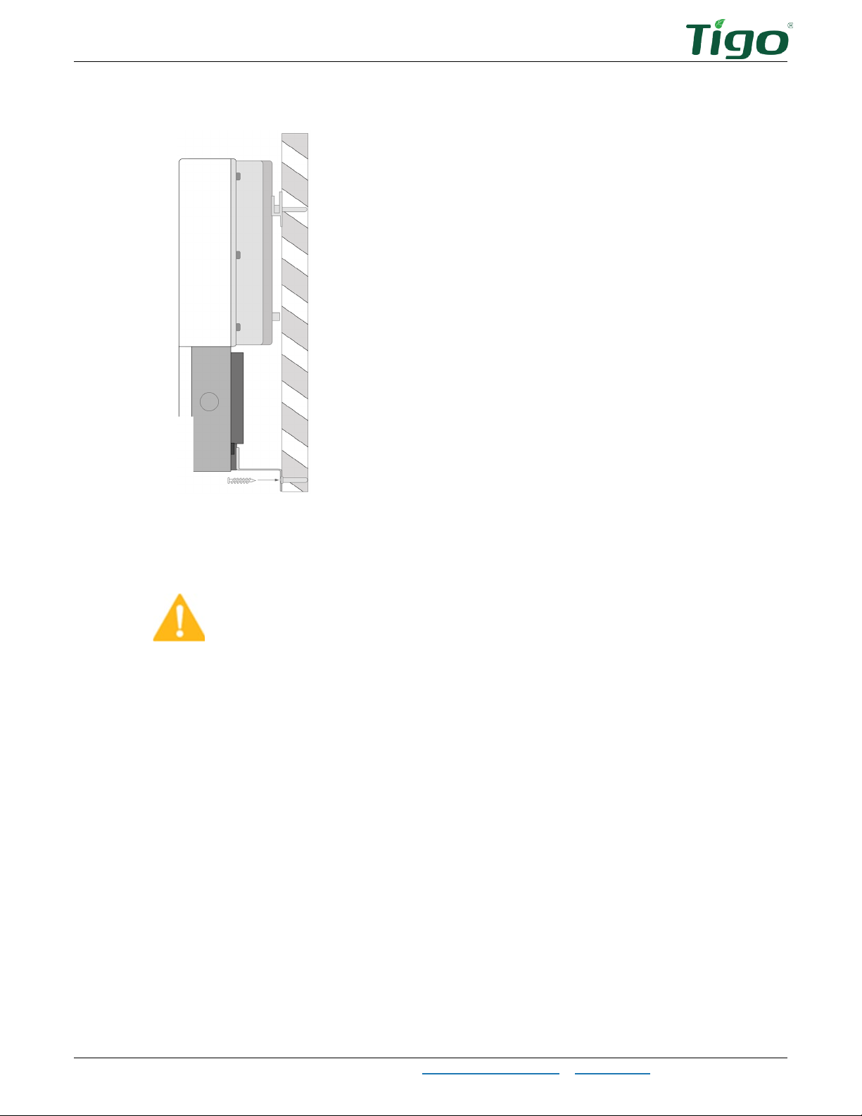
Mounting.................................................................................................................................27
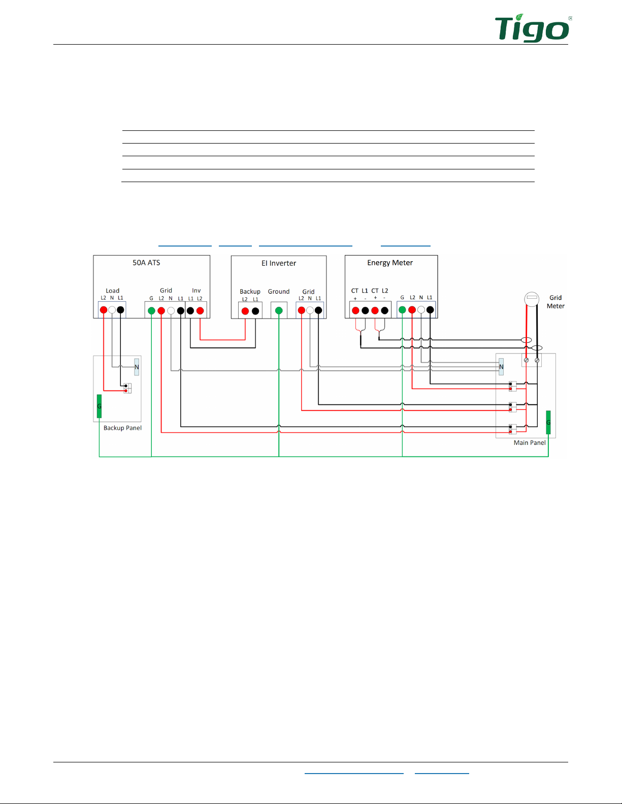
Wiring.....................................................................................................................................28
Backup Load Connections ......................................................................................................28
Grid Connections ..................................................................................................................29
Inverter Connections.............................................................................................................30
The EI Battery.............................................................................................................................31
Box Contents ...........................................................................................................................31
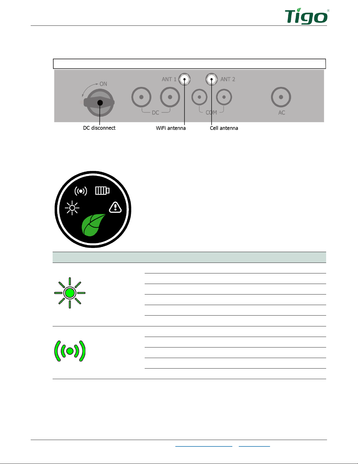
Enclosure Overview..................................................................................................................32
Place and Prepare ....................................................................................................................32
Connect to the Inverter ............................................................................................................35
Add Batteries...........................................................................................................................37
Status Indicators......................................................................................................................41
Forced Start/Shutdown.............................................................................................................42
TAP and TS4 MLPE ......................................................................................................................43
Install the Tigo Access Point (TAP) ............................................................................................43
Install TS4 MLPE ......................................................................................................................46
Commissioning............................................................................................................................48
Check Connections ....................................................................................................................48
Power On the System ...............................................................................................................48
Run the Tigo Energy Intelligence App ........................................................................................49
Set System Info....................................................................................................................49
Select Equipment..................................................................................................................50
Configure Layout ..................................................................................................................54
Configure Communication......................................................................................................58
Set Up System Access ...........................................................................................................58
Reference ...................................................................................................................................59
Error Codes .............................................................................................................................59
Inverter Warning Codes ........................................................................................................59
Inverter Fault Codes .............................................................................................................60
System Fault Codes...............................................................................................................61
Decommissioning .....................................................................................................................62
Maintenance ............................................................................................................................62