Tigo TS4-A User manual

Installation Manual
TS4-A with TAP and CCA

IMPORTANT SAFETY INSTRUCTIONS
2
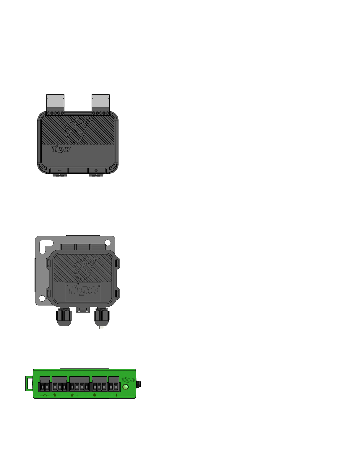
• This manual contains important instructions for installation and maintenance of the Tigo
product models TS4-A-O, TS4-A-S, TS4-A-M, Tigo Access Point (TAP), Cloud Connect
Advanced (CCA), and related Tigo software and mobile applications.
• Risk of electric shock, do not remove cover, disassemble, or repair, no user serviceable
parts inside. Refer servicing to qualied service personnel.
• Before installing or using the Tigo System, please read all instructions and warning
markings on the Tigo products, appropriate sections of your inverter manual,
photovoltaic (PV) module installation manual, and other available safety guides.
• Failure to adhere to these instructions may result in injury or death, damage to the
system, or voiding the factory warranty.
• To reduce risk of re and shock hazard, install this device with strict adherence to
National Electric Code (NEC) ANSI/NFPA 70 and/or local electrical codes. When the
photovoltaic array is exposed to light, it supplies a DC voltage to the Tigo TS4 units. The
TS4 units start in the “ON” state and their output voltage may be as high as the PV
module open circuit voltage (VOC) when connected to the module. The installer should
use the same caution when handling electrical cables from a PV module with or without
the TS4 units attached.
• Installation must be performed by trained professionals only. Tigo does not assume
liability for loss or damage resulting from improper handling, installation, or misuse of
products.
• Remove all metallic jewelry prior to installing the Tigo TS4 units to reduce the risk of
contacting live circuitry. Do not attempt to install in inclement weather.
• Do not operate the Tigo TS4 units if they have been physically damaged. Check existing
cables and connectors, ensuring they are in good condition and appropriate in rating.
Do not operate Tigo TS4 units with damaged or substandard wiring or connectors. Tigo
TS4 units must be mounted on the high end of the PV module backsheet or racking
system, and in any case above ground.
• Do not connect or disconnect under load. Turning off the Inverter and/or the Tigo
products may not reduce this risk. Internal capacitors within the inverter can remain
charged for several minutes after disconnecting all power sources. Verify capacitors
have discharged by measuring voltage across inverter terminals prior to disconnecting
wiring if service is required. Wait 30 seconds after rapid shutdown activation before
disconnecting DC cables or turning off DC disconnect.
• Always assume TS4 units are in “ON” state, or may turn on when restarting.
• The CCA must be on the same AC branch circuit as the inverter to meet rapid shutdown
requirements.
LETHAL VOLTAGE MAY BE PRESENT IN ANY PV INSTALLATION
SAVE THESE INSTRUCTIONS
03/04/2021

TABLE OF CONTENTS
Tigo System Overview 4
TS4 Flex MLPE Functions 5
Communication Accessories 6
System Overview: TS4-A 7
MLPE Installation Notes 8
String Design With TS4-A 9
TS4-A Installation 10
Communication Installation 11
TAP Installation -
Mesh Conguration 12
TAP Placement Example - Mesh 13
CCA Installation 14
CCA LED Status Guide 15
CCA & TAP Wiring 16
Modbus RS-485 Wiring Diagram
& Conguration Template 17
Conguration, Registration,
& Commissioning 18
Tigo SMART App 19
Getting Started 20
Select Equipment 21
Congure Module Layout 22
Connect CCA To Smartphone 23
Congure Network Settings –
Connect CCA To Internet 24
Commission The TS4-A Units –
Run Discovery 24
Appendix 25
Technical Specications –
TS4-A-M & TS4-A-S 26
Technical Specications – TS4-A-O 27
Technical Specications –
CCA & TAP 28
Testing Rapid Shutdown 29
TAP Placement - Legacy (Pre-Mesh) 30
Miscellaneous 31
Installation Complete 32

TIGO SYSTEM OVERVIEW
4
TS4-A
Modular smart electronics platform
Tigo Access Point (TAP)
Wireless communication device for
monitoring and safety features
Cloud Connect
Advanced (CCA)
Data logger and rapid shutdown control
Module Level Power Electronics:
Communication Accessories:
B A B A B A
AUX RS485-1 RS485-2GATEWAY POWER
access point

TS4 FLEX MLPE FUNCTIONS
The TS4 Flex MLPE platform is incremental in functionality.
Select the TS4 version with features that best address the
needs of your project.
5
For the TS4-F (Fire Safety) manual, click here
Optimization
Monitoring Safety
Monitoring Safety
Monitoring
OPTIMIZATION
SAFETY
MONITORING
TS4-A-O
TS4-A-S
TS4-A-M
• Reduced O&M costs
• PV-2.0 data synchronization
• Module bar code tracking
• CRM integration
• Warranty tracking
• Fleet management
• Shade and mismatch tolerance
• Enhanced energy yield
• Greater design exibility
• Maximized roof usage
• Plus all the benets of Safety and Monitoring
• NEC 2017 & 2020 690.12 rapid shutdown
compliant
• Module-level deactivation
• Automatic or manual shutdown
• Plus all the benets of Monitoring
4 - 123A
TS4-A-M
4 - 123A
TS4-A-S
4 - 123A
TS4-A-O

B A B A B A
AUX RS485-1 RS485-2GATEWAY POWER
COMMUNICATION ACCESSORIES
6
Tigo Access Point (TAP)
Mesh configuration:
•300 TS4 units per TAP
•900 TS4 units per CCA
•7 TAPs per CCA
Wireless range:
•33ft (10m) max between TAP and
closest TS4 unit
•115ft (35m) max between TAP and
farthest TS4 unit using mesh
Legacy configuration:
•Same as Gateway, see appendix for more details
Cloud Connect Advanced (CCA)
•CCA is required for monitoring
and rapid shutdown
•CCA is optional for optimization
and long strings
•Install near inverter with access
to AC power and internet
•Ethernet and Wi-Fi are built-in
PWR PWRDATA DATA
B BA A 120Ω
resistor
TAP/GTWY
RS485
terminal
block
RS485 port for
3rd party devices
Cable
gland
Quick
connect
DC power
input
Connector for
external switch
(optional)
access point

SYSTEM OVERVIEW: TS4-A
7
•TS4-A mounting is recommended on the upper right as shown, but can be placed on upper left
if needed (due to racking constraints, etc.)
•TS4-A cable glands must not be facing up
•Allow clearance between PV module and mounting surface for air circulation around TS4-A
•Do not drill additional mounting holes in the frame or metal bracket
Note: connect modules to TS4-A inputs before connecting outputs
TigoRapidShutdown
DONOTDISCONNECT
UNDERLOAD
4-123A
TS4-A-O
access point
B A B A B A
AUX RS485-1 RS485-2GATEWAY POWER
1. Tigo Access Point (TAP)
2. TS4-A installed on standard module
3. Cloud Connect Advanced (CCA)
4. Inverter
1 2 43
•Bracket clips to module frame without tools
•TS4-A inputs connect to module junction box,
TS4-A outputs are connected in series to form a string
•No additional grounding required
TS4-A
4 - 123A
TS4-A-O

MLPE INSTALLATION NOTES
• Note: The following TS4 products are shipped in the ON position:
• TS4-M, TS4-S, TS4-O
• TS4-A-M, TS4-A-S, TS4-A-O
• Upon exposure of the PV module to sunlight high voltage is
present. Handle with the appropriate precautionary measures.
• Optimization feature does not require CCA & TAP for operation.
• To enable Monitoring and Safety features:
• Collect the TS4 removable barcode label, install and commission
with CCA & TAP.
With add-on units, failing to follow the sequence of installation steps
may result in TS4 damage not covered under warranty.
8
4 - 123A
TS4-A-O
4-1234T
FRAME THICKNESS RANGE
GLASS
1.2mm - 3mm min. 30mm
min. 22mm
ALUMINUM FRAME
Module frame specications for mounting TS4-A:

STRING DESIGN WITH TS4-A
9
TS4-A-O: OPTIMIZATION:
Standard rules for string length
Flexible design (mixed orientations, unequal length strings in parallel)
Tolerant of shade and mismatch
TS4-A-S: SAFETY:
Standard rules for string length and design.
Requires CCA and TAP for monitoring and rapid shutdown.
TS4-A-M: MONITORING:
Standard rules for string length and design.
Requires CCA and TAP for monitoring.
Monitoring Safety Optimization
Monitoring Safety
Monitoring
4 - 123A
TS4-A-M
4 - 123A
TS4-A-S
4 - 123A
TS4-A-O

TS4-A INSTALLATION
Standard modules can be equipped with TS4-A add-on units as
shown below.
Always connect modules to TS4-A inputs before connecting outputs.
Each TS4-A must have a PV module connected to its inputs before
connecting the outputs of TS4-A units in series.
To disconnect TS4-A from a module, disconnect the TS4-A outputs
from the string before disconnecting the TS4-A inputs from the
module junction box.
10
Tigo Rapid Shutdown
DO NOT DISCONNECT
UNDER LOAD
4 - 123A
TS4-A-O DO NOT DISCONNECT
UNDER LOAD
4 - 123A
TS4-A-O
DONOT DISCONNECT
UNDERLOAD
4 - 123A
TS4-A-O
Tigo Rapid Shutdown
DONOT DISCONNECT
UNDERLOAD
4 - 123A
TS4-A-O
3
1 2

COMMUNICATION INSTALLATION
COMMUNICATION DESIGN RULES
• MESH CONFIGURATION
• 300 TS4 units per TAP
• 900 TS4 units per CCA
• 7 TAPs per CCA
• 33ft (10m) max between TAP and closest TS4 unit
• 115ft (35m) max wireless range using mesh
• No more than 10m between TS4 units on same TAP
• LEGACY CONFIGURATION
• 120 TS4 units per TAP
• 360 TS4 units per CCA
• 7 TAPs per CCA
• 50ft (15m) radius with line of sight between TAP & all TS4 units
Wireless signal range can be affected by solid obstructions. Refer to
TAP Placement Guide for more information.
11
NOTES
• All TS4 units in the same string must be assigned to the same CCA.
• For further design information, click here.
CCA and TAP CALCULATOR
• To estimate the number of CCAs and TAPs required for your
project, click here.

TAP INSTALLATION -
MESH CONFIGURATION
12
TAP attaches to module frame using built-in bracket. Mounting holes are also
available in case of frameless modules.
Place TAP within 10m of any TS4 unit in the array, with a maximum distance
of 10m between TS4 units and 35m from TAP to farthest TS4.
Connect multiple TAP units in series and leave terminating resistor in final TAP
only.
Use 4-conductor RS485 (18-22 AWG) cable between TAP and CCA.
Click here for more information on TAP placement.
access point
access point access point
PWR PWRDATA DATA
Quick connectors:
presswi reinto ter minal
OR
Connector blocks:
use screwter minals
Remove resistor to connect
another Access Point in series.
-
+BA
IN OUT
B BA A
PWR DATA
B A
B A B A B A
AUX RS485-1 RS485-2GATEWAY POWER

TAP PLACEMENT EXAMPLE - MESH
13
33ft (10m) max
230ft (70m) max
33ft (10m) max
Place TAP within 10m of any TS4 unit in the array.
Maximum distance of 10m between TS4 units that belong to a single TAP.
Maximum distance of 35m (115ft) between TAP and farthest TS4 unit.
Connect multiple TAPs in series for larger arrays.
accesspoint

CCA INSTALLATION
•CCA is required for monitoring and rapid shutdown
•Optional for optimization and long strings
•Install near inverter with access to AC power and internet
•Ethernet and Wi-Fi are built-in
14
CCA with DC transformerCCA with DIN rail power supply
Complete TAP wiring connections before powering on CCA
CCA and TAP are required for Rapid Shutdown control
Install CCA on same AC main service as inverter for automatic activation in case of AC grid loss
B A B A B A
AUX RS485-1 RS485-2GATEWAY POWER
TAP/GTWY
RS485 port for
3rd party devices
DC power
input
Connector for
external switch
(optional)
B A B A B A
AUX RS485-1 RS485-2GATEWAY POWER
100-240VAC
0.88A
50/60Hz
-
+
N
L
+V ADJ
+
B A B A B A
AUX RS485-1 RS485-2GATEWAY POWER
•Connect DC leads from power supply to CCA
•Connect AC and DC ground wires to DIN rail
•Connect AC power input to power supply
•Connect DC leads from power
supply to CCA

Auto PV-Off Error
• A blinking red and yellow LED
indicates that the system
automatically entered PV-Off mode.
• A solid red LED indicates that the
Discovery process failed or that the
CCA is not able to connect to the
Tigo server. In case of errors,
connect to the CCA using the
mobile app for more details.
User PV-Off Warning
• A blinking green and yellow LED
indicates that PV-Off mode was
activated manually.
• A solid yellow LED indicates that:
Discovery has not been run,
Discovery completed but did not
nd all expected TAPs or TS4 units, or
CCA is not able to upload data.
Connect to the CCA using the Tigo
SMART app for more details.
SMART App Activity System OK
• A blinking green LED indicates that
the mobile app is connected to the
CCA and is actively in use.
• A solid green LED indicates that
Discovery is complete and found all
expected TAPs and TS4 units, and
CCA is able to connect to the Tigo
server.
Discovery Power Off / No Status
• A blinking yellow LED indicates that
the CCA is scanning for TAPs and TS4
units (part of the commissioning
process).
• An unlit LED indicates that the CCA
is powered off.
CCA LED STATUS GUIDE
15
B A B A B A
AUX RS485-1 RS485-2GATEWAY POWER
Status LED

CCA & TAP WIRING
16
PWR PWRDATA DATA
Quick connectors:
press wire into terminal
OR
Connector blocks:
use screw terminals
Remove resistor to connect
another Access Point in series.
-
+BA
IN OUT
B BA A
PWR PWRDATA DATA
Quick connectors:
press wire into terminal
OR
Connector blocks:
use screw terminals
Remove resistor to connect
another Access Point in series.
-
+BA
IN OUT
B BA A
B A B A B A
AUX RS485-1 RS485-2GATEWAY POWER
B A B A B A
Connect multiple TAP units in series and leave terminating resistor only in nal TAP.
If using the quick connectors, remove the terminal block from the TAP and strip
approximately 3cm of insulation from the end of the cable.
Use a small athead screwdriver to press the conductors into the quick connectors.
The individual conductors do not require stripped ends.
Connect all communication cables before powering on CCA.
PWR DATA
B A
120Ω
resistor
Terminal
block
Quick connect
terminals
+ B
A
-

MODBUS RS-485 WIRING DIAGRAM
& CONFIGURATION TEMPLATE
• Up to 32 Modbus RS-485 devices can be connected to a
single Cloud Connect/CCA
• All devices must have a unique Modbus address
• All devices connected in series must have the same baud
rate, parity, and stop bit settings
• Check device manual for Modbus settings
17
RS-485 Modbus terminal RS-485 Modbus terminal
B A B A B A
AUX RS485-1 RS485-2GATEWAY POWER
B A B A
To Modbus
Device(s)
To TAP(s)/
Gateway(s)
Modbus Device #1
Manufacturer:
Model:
Type of Device:
Electrical Voltage:
Single or 3 Phase:
CT Rating:
Modbus Address:
Baud Rate:
Parity:
Stop Bits:
Modbus Device #2
Manufacturer:
Model:
Type of Device:
Electrical Voltage:
Single or 3 Phase:
CT Rating:
Modbus Address:
Baud Rate:
Parity:
Stop Bits:
Cloud Connect Advanced
(CCA)
RS-485 communication cable with shield
120Ω resistor across + and - terminals
on the last Modbus device in series
G G+ +
- -
Click here for more info about setting up inverters, meters, & sensors

CONFIGURATION, REGISTRATION,
& COMMISSIONING
• For residential systems, perform configuration, registration,
and commissioning via the Tigo SMART App.
• For non-residential systems, perform site configuration
online at https://smart.tigoenergy.com.
Recommended procedure:
18
OR
Enter site layout online
Type or scan TS4 barcodes
into online layout
Use Tigo SMART app to run
Discovery while on site
Enter site layout online
Type or scan TS4 barcodes
into Excel .csv template*
Upload Excel .csv
template to layout
Use Tigo SMART app to run
Discovery while on site
* Download the pre-formatted .csv template from the Layout step of the site builder
4 - 123A
TS4-A-O
4-1234T

TIGO SMART APP
19
Commissioning a new system using the Tigo App 3.0
Install ‘Tigo SMART’ from the App Store or
Google Play
Use the Tigo SMART app to:
• Create a system
• Input owner info
• Enter inverter & module types
• Congure layout and scan barcodes
• Congure network
• Commission Tigo hardware
• Monitor production

GETTING STARTED
20
Requires active mobile data connection
To proceed with a new installation, tap ‘+’
at the top right of the display
To service or monitor an existing system that
has already been congured, tap on that
system in your list
Enter a name and address for the new
system and create a user account for the
system owner
If you do not have an installer account, tap
‘Enroll’ to create a new account. All system
data can also be accessed and edited
here: smart.tigoenergy.com
Other manuals for TS4-A
1
This manual suits for next models
3
Table of contents
Other Tigo Safety Equipment manuals
Popular Safety Equipment manuals by other brands

AquiTron
AquiTron AT-GU Installation & operating manual

Plastimo
Plastimo 63743 quick start guide

Petzl
Petzl PIRANA manual

babcockdavis
babcockdavis Lume-A-Lite BEM-DSH1-10 Installation, operation and maintenance manual

Carl Stahl Kromer
Carl Stahl Kromer EASY BALANCER ER00 Series operating instructions

Petzl
Petzl AXIS 11 MM 100 M manual