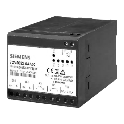
A 01/13 2-channel Binary Signal Transducer Page 3 of 40
s
Page 2 of 40 2-channel Binary Signal Transducer A 01/13
s
0General Notes
This manual includes all information required for the intended use of the
products described therein. It is intended for technically qualified
personnel who are especially trained or have special knowledge on the
fields of instrumentation, control and automatic control engineering (in
the following called automation). The knowledge and the technically
correct interpretation of the safety instructions and warnings included
in this manual are prerequisite for safe installation and commissioning,
aswellasforthesafetyduringoperationandmaintenanceoftheproduct
described.Onlyqualifiedpersonnelasdefinedoverleafhave the technical
knowledge required to interpret and apply the general safety notes and
warnings correctly in the individual cases. This manual is an integral part
of the delivery. For reasons of better overview, however, it cannot take
into account every detail for all design types of the product described
andcannotconsidereveryconceivablesituationwithregardtoinstallation,
operation or maintenance. For further information or if special problems
should arise, which are not treated precisely enough in this document,
please contact your local Siemens office or send your request directly to
the address stated on the last page of this manual.
Furthermore, we wish to point out that the contents of this product
documentation are neither part of any previous or current agreement,
promiseorlegal relationship, nor do theyimplyanymodificationsthereto.
.
Table of Contents
0General Notes ...............................................................................3
1Operating instructions .............................................................. 10
1.1 Scope of application.................................................................. 10
1.2 Applications .................................................................................14
1.2.1 Example of applications ...........................................................14
1.2.2 Binary signal transmission via leased line ..................................
modem LOGEM928 and LGH28.8D (firmware 4.13) ............16
1.2.3 Binary signal transmission via leased line ..................................
modem MT2834BLG (firmware 3.16d)...................................20
1.3 Technical data .............................................................................22
1.4 Description of the functional units ........................................26
1.4.1 Position and assignment of the terminals ..............................26
1.4.2 Switch positions and RS232 interface ....................................28
1.4.3 Dimensional drawings ..............................................................33
1.5 Ordering data ..............................................................................34
1.6 Installation and commissioning..............................................35
1.7 Settings.........................................................................................37
1.8 Maintenance ................................................................................37
List of Illustrations
Fig.1: Exampleof application ........................................................................ 14
Fig.2: Assignment ofconnecting cable modem- binary signaltranformer ...... 18
Fig. 3: Postion and assignment of terminals ................................................... 26
Fig. 4:Position ofthe switches ...................................................................... 28
Fig.5: Switching thresholdof the binary inputs .............................................. 32
List ofTables
Tab.1: Binary inputs...................................................................................... 13
Tab.2: Connector andcable for two-wire leasedline operation ........................17
Tab.3: Connector and cable for four-wireleased line operation ....................... 21
Tab. 4: Screw-type terminals ......................................................................... 27
Tab.5: RS232interface,9-pole sub-Dsocket .................................................. 29
Tab. 6: S1, DIP switch (2) ............................................................................... 29
Tab. 7: S2, DIP switch (8) ............................................................................... 30
Tab. 8:Switching threshold of thebinary inputs............................................. 32
