Timan 3330 User manual

www.timan.dk
”Comfortably Better”
Timan 3330
Type-serialnumber: 712000x00xAAAA
OPERATION MANUAL
OPERATION MANUAL
OPERATION MANUAL

1
CONTENTS
1. MACHINE IDENTIFICATION DATA .........................................................................................2
2. INTENDED USE OF THE MACHINE..........................................................................................4
2.1 WEIGHT TABLE FOR USING TOOLS AND ACCESSORIES............................................................4
2.2 THE PERMISSIBLE LOAD ON THE FRONT OF THE MACHINE......................................................5
2.3 PERMISSIBLE LOAD ON THE REAR END OF THE MACHINE .......................................................6
2.4 MAXIMUM PERMISSIBLE SIDE LOAD OF THE MACHINE ...........................................................7
3. NOISE (SOUND PRESSURE) AND VIBRATIONS ....................................................................8
3.1 SOUND PRESSURE MEASUREMENT ..........................................................................................8
3.2 MEASURING VIBRATIONS........................................................................................................8
4. MACHINE CONSTRUCTION.......................................................................................................9
5. STEERING COLUMN, OPERATOR'S GRIP, CABINET AND AIR SWITCHES....................10
5.1 SIDE PANEL ...........................................................................................................................11
5.2 DISPLAY ................................................................................................................................13
5.3 IGNITION ...............................................................................................................................14
5.4 FOOT PEDALS ........................................................................................................................14
5.5 STEERING COLUMN MULTI-SWITCH ......................................................................................15
5.6 CEILING.................................................................................................................................16
6. MAIN CIRCUIT-BREAKER, FUSES AND RELAYS, ERROR CODES ..................................17
6.1 MAIN CIRCUIT-BREAKER.......................................................................................................17
6.2 MAIN FUSES AND RELAYS REAR. ..........................................................................................18
6.3 FUSES IN THE CABINET ROOF ................................................................................................19
6.4 FUSES IN THE CABIN..............................................................................................................20
6.5 RELAYS FRONT......................................................................................................................21
6.6 13 POLE TRAILER SOCKET REAR............................................................................................22
6.7 ERROR CODES .......................................................................................................................22
7. USE OF THE MACHINE - QR CODE ........................................................................................23
7.1 THE STRUCTURE OF THE MACHINE........................................................................................23
7.2 DRIVING ................................................................................................................................23
7.3 MAINTENANCE......................................................................................................................23
7.4 ADDITIONAL EQUIPMENT ......................................................................................................24
8. MAINTENANCE DATA..............................................................................................................25
8.1 HYDRAULIC OIL ....................................................................................................................25
8.2 COOLANT ..............................................................................................................................25
8.3 LUBRICATION........................................................................................................................25
8.4 ENGINE OIL ...........................................................................................................................25
8.5 AIR CONDITIONING ...............................................................................................................25
8.6 WHEELS ................................................................................................................................25
9. TECHNICAL DATA ....................................................................................................................26
10. CE DECLARATION OF CONFORMITY...............................................................................27

2
Congratulations on your new Timan 3330
This operator's manual will assist you in the proper use, adjustment and maintenance of your
new machine.
Before you start to drive or work with the new machine, read this operator's manual
thoroughly, in particular the section on safety rules.
The indications right and left in the manual and in spare parts lists is the machine seen from
behind in the driving direction.
1. MACHINE IDENTIFICATION DATA
Manufacturer: Timan A/S
Fabriksvej 13
6980 Tim
Tel.: +45 97 330 360
timan@timan.dk
Seller (to be completed by the seller)
Title / Name
Address
Zip code
State/country
Telephone
MACHINE IDENTIFICATION DATA
3
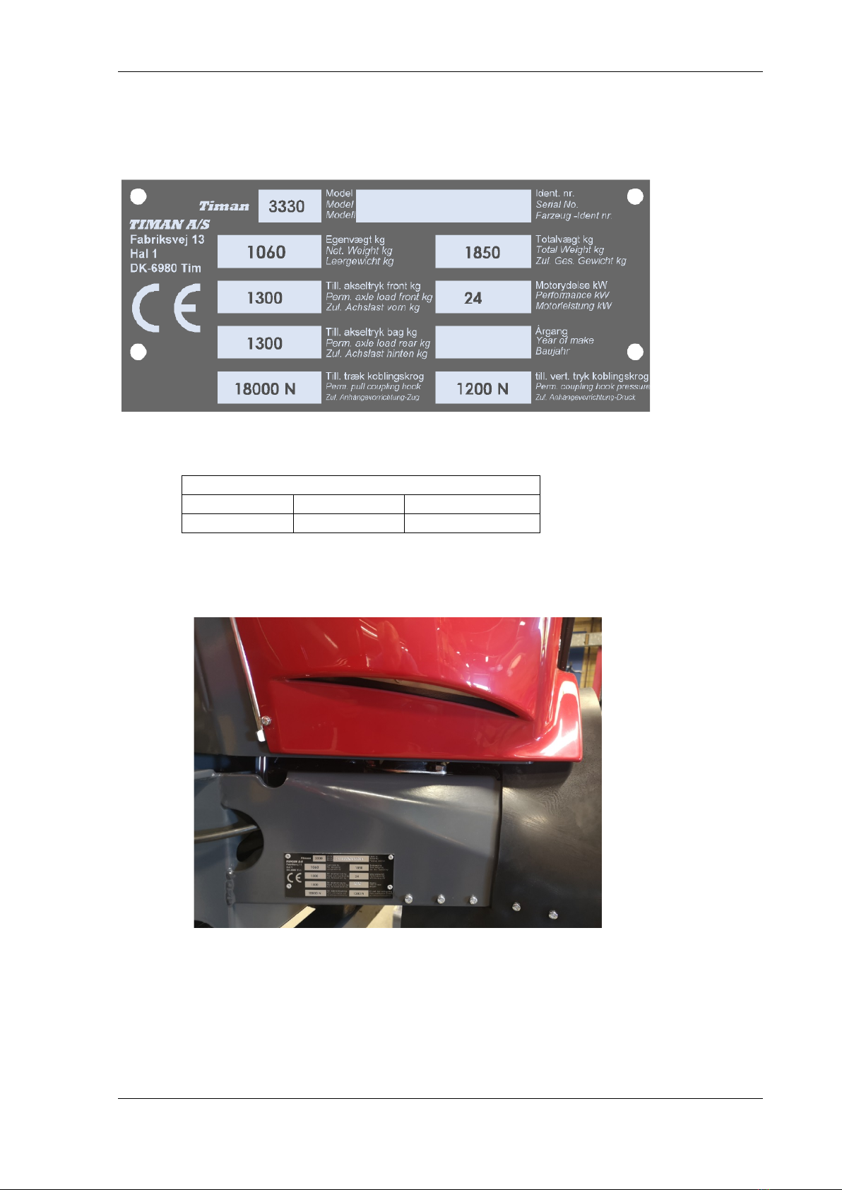
Type label
Identification number
712000X00X1001
Type
Serial
Machine number
712000
00
1001

INTENDED USE OF THE MACHINE
4
2. INTENDED USE OF THE MACHINE
Timan 3330 is a universal tool carrier that can perform many tasks depending on the type of
equipment attached to it. It could, for example, cut grass, sweep, cut live fences, remove
snow, salt roads etc.
The respective tools may be attached to the machine on the front and at the rear. Furthermore,
a combination of a fork and ball joint for towing tools and carts can be attached to the
machine.
Timan 3330 may drive on public roads, and it is intended for professional operators.
The use of the machine depends on its tasks.
However, you must ensure that the loads and weights specified below will never be exceeded.
Using accessories which exceed the maximum specifications specified below can lead to
malfunctions, machine failure, damage to someone else's property and injury to the driver
and/or other persons. The Timan guarantee does not cover any malfunctions or machine
failures caused by using non-corresponding accessories.
2.1 Weight table for using tools and accessories
Front axle Rear axle Maximum permissible
Maximum permissible Maximum permissible
1300 kg 1300 kg 1860 kg
Important: Only towbars approved by Timan A / S may be fitted.
The maximum permissible load of the towing pole is specified
on the picture. It is important to ensure that the vertical load of
the towing pole is never greater than 120 kg (up/down). This rule
applies even if the vehicle is connected with a coupling head
and in the towing pole.
If the vehicle is connected with a coupling head (see Fig no. 1 and 2), the maximum
permissible weight (total weight) of the vehicle must be 1500 kg if it is
equipped with overrun brakes and 600 kg if it is not.
Alternatively, the towing pole may be loaded with the vehicle,
which is connected in the towing pole (see Fig no. 3). This may
be done with the maximum permissible weight (total weight)
of 1850 kg if the vehicle is equipped with overrun brakes.
If the vehicle is connected with a towing pole, it must be a four-wheel
vehicle (four-wheel drive) with a turntable steering axle
(see Fig. no. 4 and 5) which has a maximum permissible mass
(total mass) of 1850kg if it is equipped with overrun brakes
and 600 kg if it is not.
1
2
5
4
3
INTENDED USE OF THE MACHINE
5
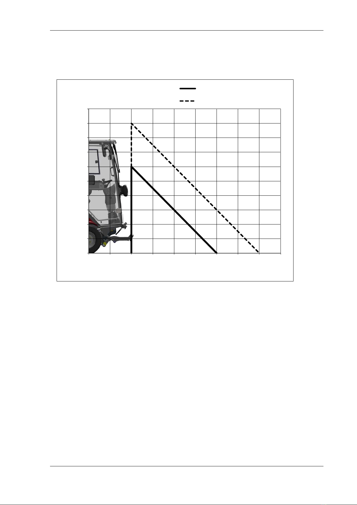
2.2 The permissible load on the front of the machine
The maximum permissible load on the lifting arms is shown in the diagram below
The load must be positioned in the middle between the front wheels.
In the load table, point 0 is shown on the lifting arm handle if it is in a vertical (upright)
position. It is measured from the handle on the lifting arms where the quick coupler is
connected (quick coupler device).
For example, the arms may lift 150 kg with a load placed 800 mm away from handle without
loading the rear end. When minimal load amounting to 200 kg is on the rear end, the arms
may lift 300 kg at the same distance.
0
50
100
150
200
250
300
350
400
450
500
-800 -400 0400 800 1200 1600 2000 2400 2800
Kg
mm
Till. vægt front -Perm. load front Ingen bagvægt - Without rear weight
Min 200kg bagvægt - Min 200kg rear weight
INTENDED USE OF THE MACHINE
6
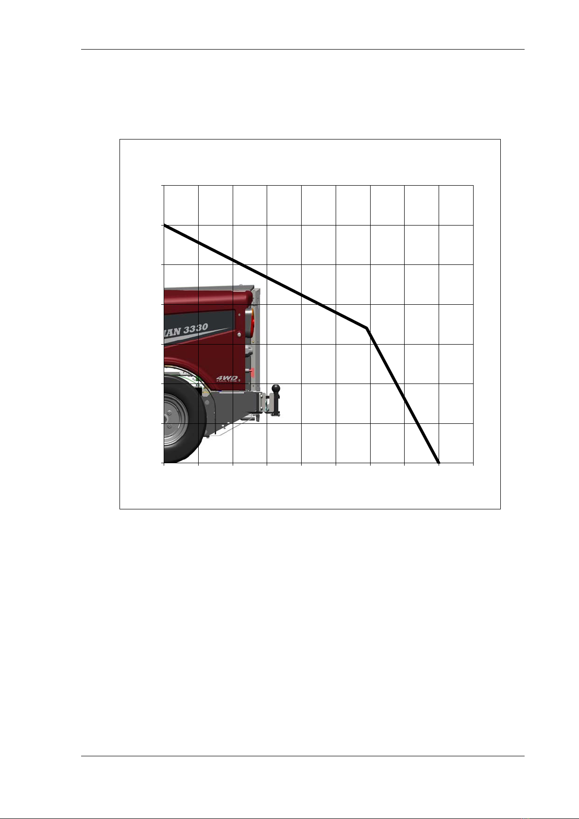
2.3 Permissible load on the rear end of the machine
The maximum permissible load on the rear end of the machine and load platform is specified
in the diagram below.
Caption: Permissible load on the rear end of the machine
The load must be positioned in the middle between the rear wheels.
The maximum permissible load on the load platform is 600 kg above the centre of the rear
wheels.
The distance from centre of the rear wheels to the rear end of the machine is 600 mm.
For example, the rear end may carry a load weighing 400 kg with the centre of gravity
positioned 900 mm away from the centre of the rear wheels - 300 mm if the measurement is
taken from the rear end of the machine.
Important: It is necessary to use the original Timan A/S tool frame when loading the rear
end.
0
100
200
300
400
500
600
700
0200 400 600 800 1000 1200 1400 1600 1800
kg
mm
Till. vægt bag -Perm. load rear
INTENDED USE OF THE MACHINE
7
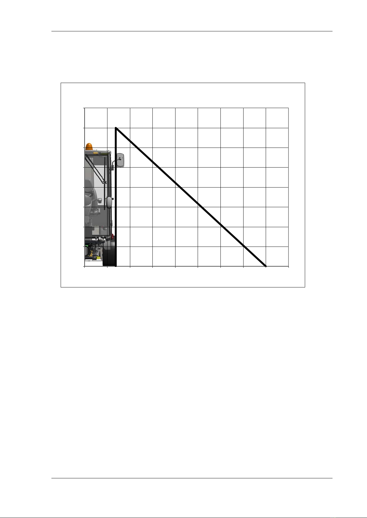
2.4 Maximum permissible side load of the machine
The maximum permissible side load of the machine is specified in the diagram below.
Caption: Maximum permissible side load of the machine
The mass table shows point 0 between the lifting arms and on the ball joint at the rear end of
the machine (if it is attached).
Equipment for side loading may either be fixed to the front on the lifting arms or to the rear.
The stated load is on the lifting arm holder or the rear end of the machine. If the tool is fixed
further away than the holder, on the rear end of the machine, the weight that can be suspended
from the machine decreases.
Important:
Only one side load may be suspended from the machine at a time.
For example, the machine may carry a load weighing 200 kg with the centre of gravity
positioned 1700 mm away from the centre of the lifting arms.
0
50
100
150
200
250
300
350
400
0400 800 1200 1600 2000 2400 2800 3200 3600
Kg
mm
Till. side vægt -perm. side load

NOISE (SOUND PRESSURE) AND VIBRATIONS
8
3. NOISE (SOUND PRESSURE) AND VIBRATIONS
3.1 Sound pressure measurement
5 sound pressure measurements were taken on the machine.
Driving noise from the EU 985/2018 Annex II: 74 dB
Standing noise based on EU 985/2018 Annex II: 71 dB
Source strength measurement without equipment LWA based on ISO 6395: 2008 105 dB
Source strength measurement with sweeping n equipment LWA based on ISO 6395: 2008
102 dB
Sound level cabin EU1322 / 2014 method B: 79 dB
3.2 Measuring vibrations
Two vibration measurements were taken
-The vibration of the body on the seat was
measured.
-Vibration of the hands/arms on the steering
wheel was measured.
The measurements were taken with VibroControl.
A test procedure according to DS/EN 1032 was used.
Measurements were taken in 2 various operating situations
-Driving on a road at a speed of 27 km/h.
Motor speed (revolutions) 3600 rpm
-Mowing grass with a Timan 1,35 m mowing conditioner
Driving speed: 6 km/h
Motor speed (revolutions) 3000 rpm
Body vibration when driving on a road: aw max = 0.48 m/s2
Body vibration when mowing grass: aw max = 0.69 m/s2
Vibration of hands and arms when driving on a road:
ahv = 0.60 m/s2
Vibration of hands and arms when mowing grass:
ahv = 1.08 m/s2
Vibration measurement uncertainty: ± 10 %

MACHINE CONSTRUCTION
9
4. MACHINE CONSTRUCTION
It is an articulated machine which thus has a very small turning radius. The joint is located
midway between the front and rear wheels, thus the rear wheels follow the route of the front
wheels. The joint is firmly attached from the side in order to ensure greater stability when
loads are being lifted. The machine also drives more smoothly on uneven surfaces. The
machine is controlled by a control cylinder and Orbitrol connected to the hydraulic pump,
which facilitates rotation of the steering wheel and machine even in difficult conditions.
The gasoline motor is located in the rear. The driver's cab and lifting arms are located in the
front.
Driving forward is enabled by a hydrostatic device with a pump and 4 hydraulic wheel
motors. The four-wheel drive is always connected in order to ensure optimal tractive force/
pulling force.
The respective tools (attachments) may be attached to the machine on the front and on the
back. The tools may also be lifted with the lifting arms. Furthermore, a combination of a fork
and ball joint for towing tools and carts may be attached to the machine.
STEERING COLUMN, OPERATOR'S GRIP, CABINET AND AIR SWITCHES.
10
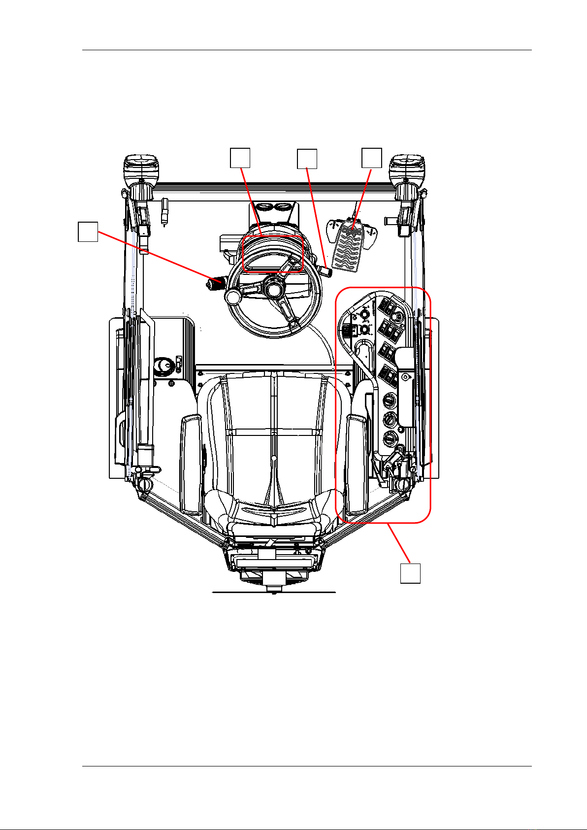
5. STEERING COLUMN, OPERATOR'S GRIP, CABINET AND AIR SWITCHES.
Cabin, controls, display and ceiling
1. Side panel
2. Display
3. Ignition lock
4. Accelerator
5. Steering column multi-switch
6. Ceiling
1
2
4
5
3
STEERING COLUMN, OPERATOR'S GRIP, CABINET AND AIR SWITCHES.
11
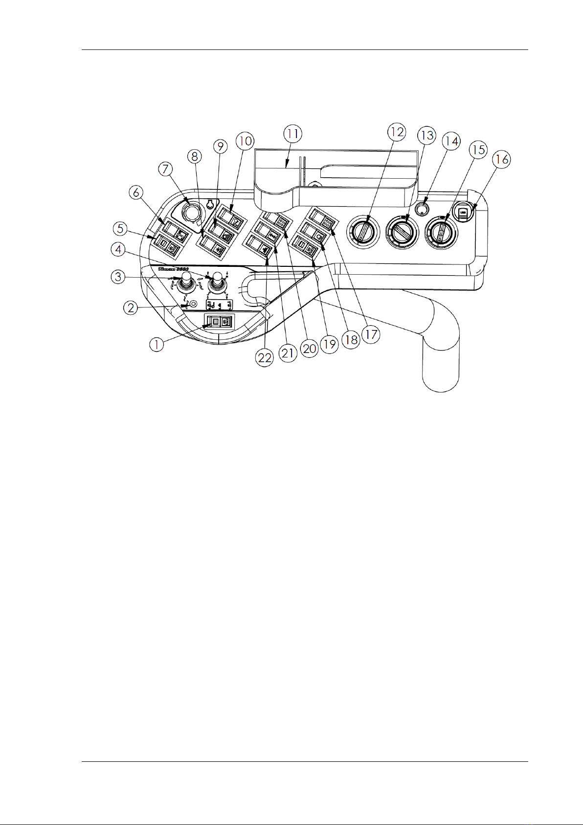
5.1 Side panel
1. Main starter for PTO.
Both the PTO (front [5] and rear [19]) + 12V switch [22] pass through this switch. This
makes it possible to start and stop the front and rear tools at the same time. Note that
there is a delay of approx. 3 seconds built into the front PTO.
2. Flow position light.
Lights up when flow position is activated. The flow position is used when the front-
mounted tool must follow the ground (flow).
3. Joystick that controls the lift arms.
If the joystick is pushed forward, the lift arms are lowered. When pushed forward, the
lift arms are raised. Pressing to the left activates the flowing position.
4. Joystick maneuver.
This joystick is used to control the maneuver valve. E.g. which way the broom turn
when mounted.
5. Switch for front hydraulic PTO jack.
The handle activates the 2 large quick-release clutches on the front of the hydraulic
panel. A delay of approx. 3 seconds is built in. Note: it is not possible to start the
machine if this switch is activated. While the PTO jack is activated, the engine stops
when the driver leaves the seat. The function is started with joint activation [1]
6. Switch to change direction of rotation on the front PTO.
7. Potentiometer for changing the engine’s rpm.
When the potentiometer is set to 0, the engine’s rpm are automatically adjusted as a
function of the motor’s load.
8. Switch for operating 3-pole electrical connectors on the front panel of the machine.

STEERING COLUMN, OPERATOR'S GRIP, CABINET AND AIR SWITCHES.
12
Used, among other things, on the sweep/suction system to adjust the rotation speed of
the brushes.
9. Light switch. Step 1 position light - Step 2 headlight
10. Cruise control.
When the desired travel speed is achieved with the accelerator, the switch is activated
and this speed is maintained. The function is deactivated by pressing the switch, by
activating the brake pedal or by activating the direction selector on the accelerator.
11. Cup holder and holders for mobile phone and ballpoint pen.
12. Air fan regulator.
The fan control has 4 steps, from 0 to 3. If there is a lot of dew on the windows and the
fan is set to step 3, it may be advantageous to open the side window slightly to quickly
get rid of large amounts of moist air.
13. Heat supply regulator.
14. Air conditioning on/off.
15. Regulation of air conditioning.
Note that the fan must be set to at least step 1 to switch on the air conditioner. The air
conditioning can be used to dehumidify the windows in winter. Set the cooling control
to the minimum and the heating control to the maximum. Dehumidified air will then
enter the cabin, and the dew on the window panes is quickly removed.
16. USB Plug with constant power.
17. Switch 12V reversible S70 (Legs no. 8 and 9 in 13 pole connectors)
Used, for example, to regulate the spreading speed of the roller spreader if it is
electrically controlled.
18. The rear PTO is only switched on when the machine is moving forward.
Used, among other things, in conjunction with roller applicator so that it starts and
stops in step with the progress of the machine.
19. Switch for rear PTO.
Note: It is not possible to start the machine if this switch is activated. Turn on with
common PTO [1]
20. Switch 12V reversible S72 (pin no. 11 and 12 in 13 pole connectors).
Used, for example, to regulate the application quantity of the roller spreader if it is
electrically controlled.
21. Switch for the bidirectional hydraulic jack at the rear of the machine. Used, among
other things, to raise and lower the tipper.
22. Contact 12V in trailer socket.
Used to turn on/off the water on the front broom and tank when the sweep suction is
used. This switch turns on and off together with common start [1]

STEERING COLUMN, OPERATOR'S GRIP, CABINET AND AIR SWITCHES.
13
5.2 Display
1. Hydraulic oil level. Warning, and low-level acoustic alarm.
2. Charging indicator.
3. Engine Warning Light. Engine fault. Error codes appear on the information display.
4. Engine oil pressure. Warning if oil pressure is too low, and an acoustic alarm.
5. Differential lock activated (not available on Timan 3330).
6. Hydraulic oil temperature. Warning if the hydraulic oil temperature gets too high.
7. Parking brake activated.
8. Rotating beacon activated.
9. Hazard lights enabled.
10. Low beam activated.
11. High beam activated.
12. Trailer indicator light activated.
13. Fuel level warning, at low level.
14. Fuel level indicator.
15. Left indicator.
16. Right indicator.
17. Engine water temperature indicator.
18. Engine water temperature warning in the event
of high temperature.
19. Digital display.
20. Driving speed.
21. Revolutions per minute.
22. Set points for cruise control.
23. Timer.
24. Drive mode - ROAD or WORK mode - toggles between modes with hand throttle
potentiometer.
25. Driving direction. F = Forward, R = Reverse.
8
1
2
3
4
5
6
7
8
9
10
11
12
13
14
15
16
17
18
19
20
21
22
25
23
24
STEERING COLUMN, OPERATOR'S GRIP, CABINET AND AIR SWITCHES.
14
5.3 Ignition
0: Off Position which allows the key to be inserted or removed from the start switch.
When the key is in this position, the gasoline engine is stopped.
I: On Ignition is on
II: Start Engine start signal
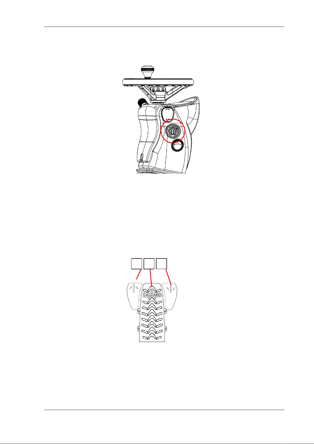
5.4 Foot pedals
1. Direction selector for moving forward.
2. Potentiometer accelerator.
If the pedal is activated without one of the directional switches being activated, the
engine speed will increase without the machine moving.
3. Direction selector for reversing.
1
2
3
STEERING COLUMN, OPERATOR'S GRIP, CABINET AND AIR SWITCHES.
15
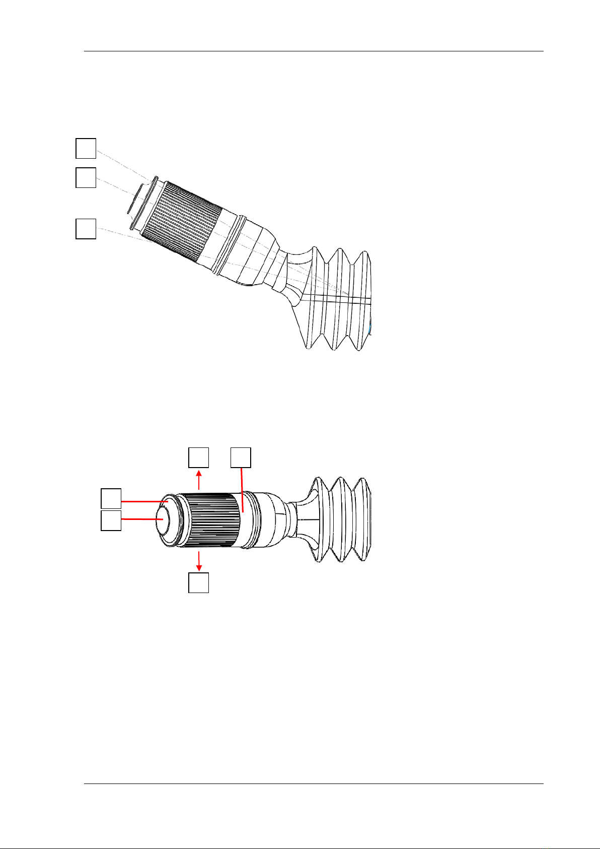
5.5 Steering column multi-switch
1. Flash high beam.
2. Low beam:
3. High beam:
4. Rotary wiper switch.
J Intermittent wiper function.
0: No wiper function.
I: Low speed wiper function.
II: High speed wiper function.
5. Window washer function.
6. Horn.
7. Indicate right.
8. Indicate left.
1
2
3
4
5
6
7
8

STEERING COLUMN, OPERATOR'S GRIP, CABINET AND AIR SWITCHES.
16
5.6 Ceiling
1. Speakers.
2. Radio (see separate operating instructions).
3. Front working light.
4. Rear working light.
5. Rotating beacon on machine and tools (pin 13 in 13 pol connector)
6. Working light on tools (extra equipment pin 10 in 13 pol connector).
7. Change between camera (extra equipment)
8. Hazard lights.
9. Cabin light.
10. Fuse box with 6 flat fuses (See page 19).
MAIN CIRCUIT-BREAKER, FUSES AND RELAYS, ERROR CODES
17
6. MAIN CIRCUIT-BREAKER, FUSES AND RELAYS, ERROR CODES
The machine's electrical system is divided into 6 different areas:
1. Main circuit-breaker.
2. Main fuses and relays rear.
3. Fuses front.
4. Fuses ceiling.
5. Relays under seat.
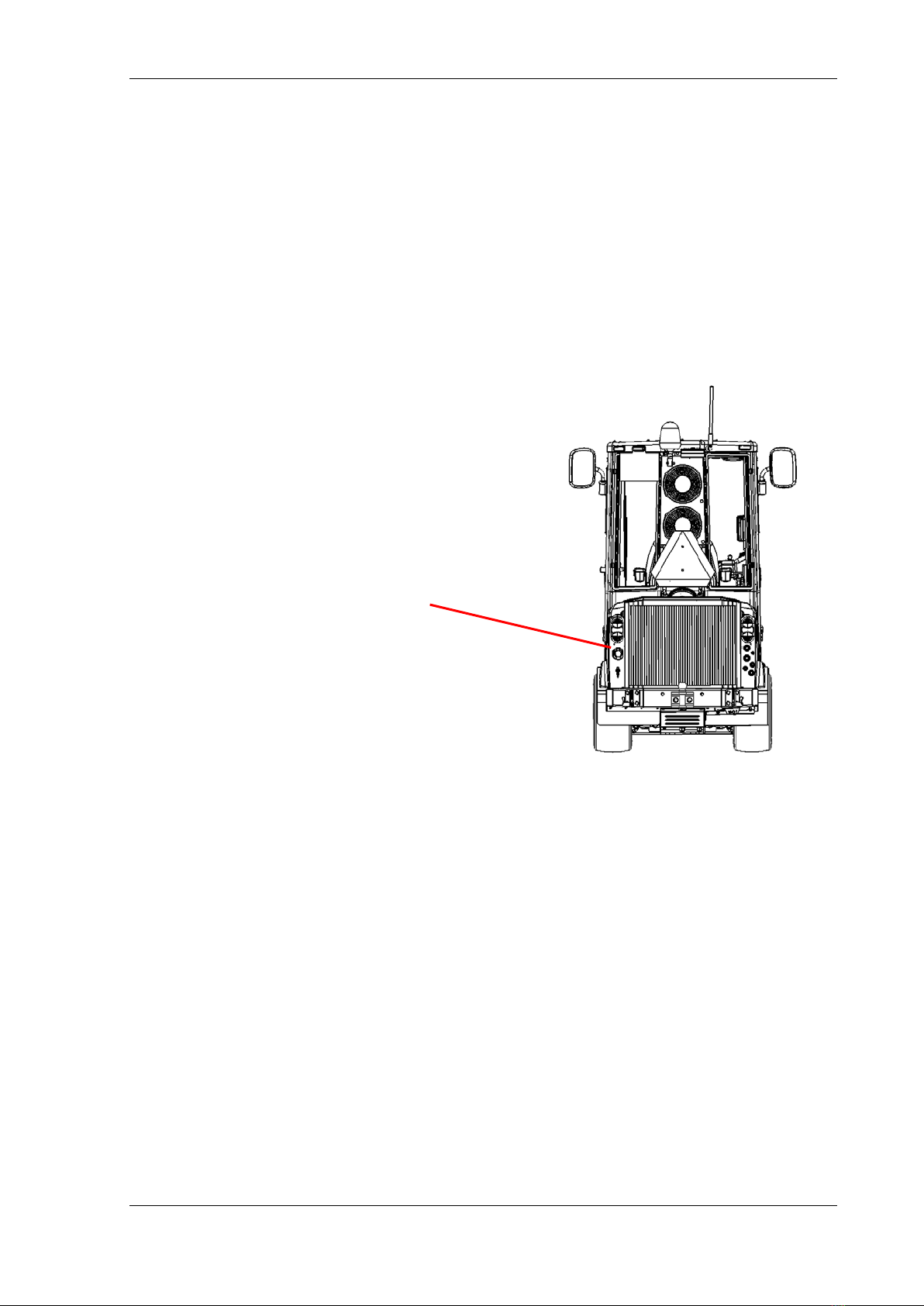
6.1 Main circuit-breaker.
The machine is equipped with a main circuit breaker on the electrical system. The circuit
breaker is located in the rear left of the machine, at
the bottom of the rear frame. The main circuit
breaker has a removable key, which can be removed
as an extra anti-theft device.
The main circuit breaker breaks the connection to the
battery and must always be disconnected if welding
is performed on the machine
Main circuit breaker with key
MAIN CIRCUIT-BREAKER, FUSES AND RELAYS, ERROR CODES
18
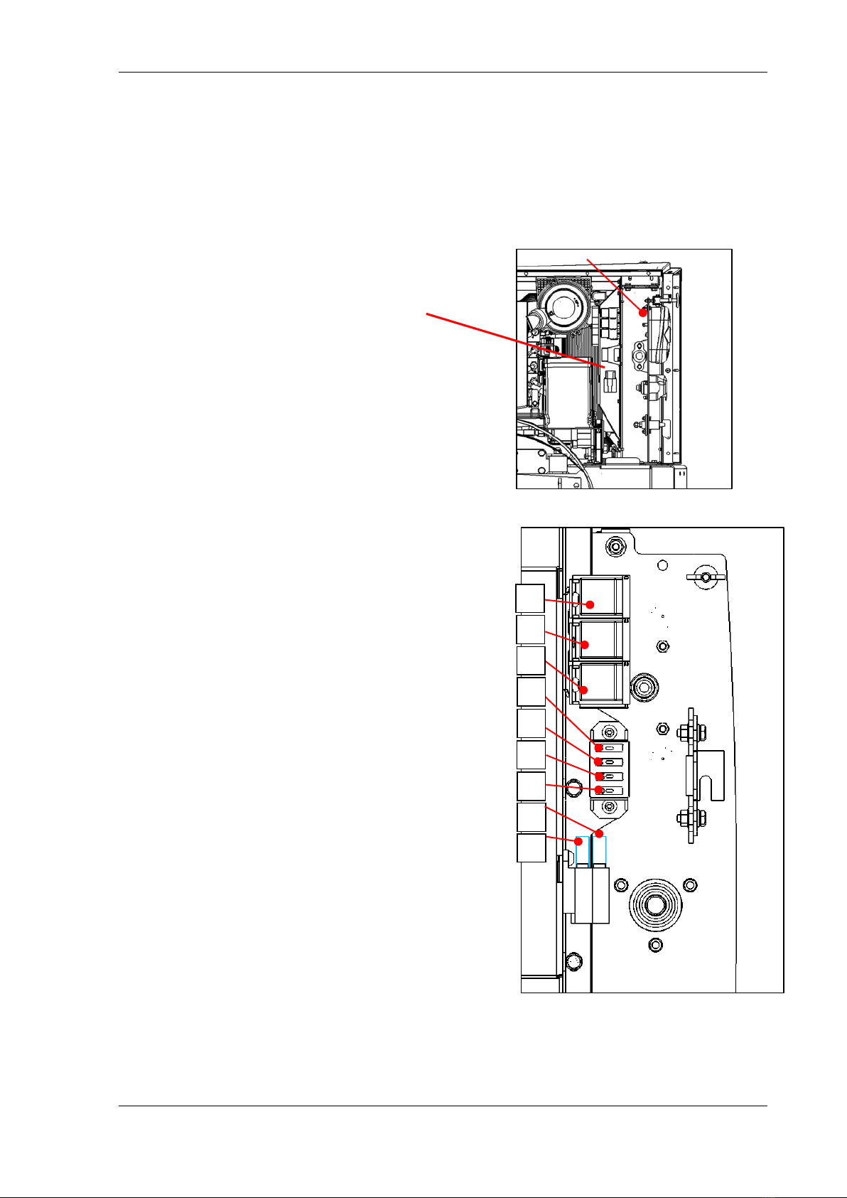
1. MR1 - Start relay Kubota motor
2. MR2 - Power relay Kubota motor
3. MR3 - ETV relay Kubota motor
4. F4-1 30 A motor control Kubota
5. F4-2 15A constant current for pump control
6. F4-3 5A feedback start signal Kubota motor control
7. F4-4 5A wheel sensor, oil level and hydraulic tank
temperature.
8. Main fuse 60A MF2 - Generator
9. Main fuse 60A MF1 main current machine
6.2 Main fuses and relays rear.
IMPORTANT: Never replace fuses with fuses that have greater ampere values. There is
always a reason why a fuse blows. Investigate the cause and remedy the problem before
inserting a new fuse.
The fuse box is located on the left side of the engine,
behind the taillight. Access is achieved by dismounting
the side screen, loosening the wing screw and
removing the screen.
7
6
5
4
3
2
1
8
9
MAIN CIRCUIT-BREAKER, FUSES AND RELAYS, ERROR CODES
19
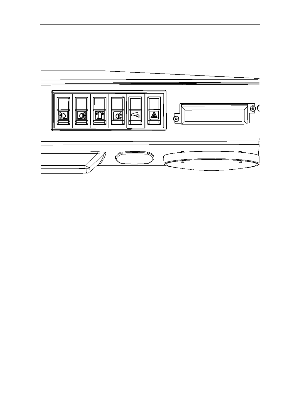
6.3 Fuses in the cabinet roof
The fuse box sits on the right side of the cabinet roof.
F3-1 15 A Work light front.
F3-2 10A Work light rear.
F3-3 10 A Rotating beacon/Strobe light.
F3-4 10 A Work light tool.
F3-5 10 A Radio.
F3-6 5 A Cabin light.
F3-6
F3-5
F3-4
F3-3
F3-2
F3-1
Table of contents
Other Timan Farm Equipment manuals

Popular Farm Equipment manuals by other brands


GREAT PLAINS
GREAT PLAINS Yield-Pro PL5800 Predelivery Manual

LUCAS
LUCAS Castor 134 instruction manual

Vicon
Vicon Extra 828T PRO instruction manual

Agrimate
Agrimate AM-MPTC-6500-6D user manual

Pessl Instruments
Pessl Instruments METOS iMETOS WorkTrack user manual

AG SPRAY
AG SPRAY FSTS-40-2.5-4 owner's manual