manuals.online logo
Brands
  1. Home
  2. •
  3. Brands
  4. •
  5. J&M
  6. •
  7. Farm Equipment
  8. •
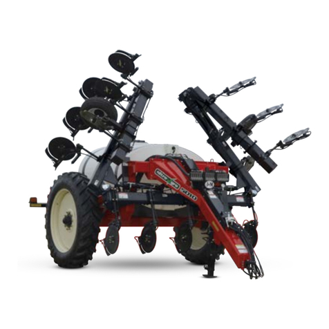
  9. J&M Nitro Gro 5010 User manual

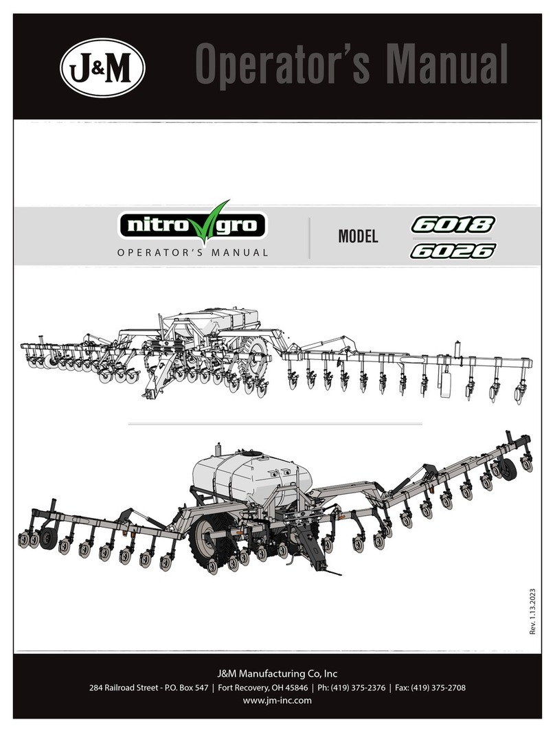
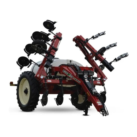
J&M Nitro Gro 5010 User manual

J&M Manufacturing Co, Inc
284 Railroad Street - P.O. Box 547 | Fort Recovery, OH 45846 | Ph: (419) 375-2376 | Fax: (419) 375-2708
www.jm-inc.com
Rev. 10.2.2019
ASSEMBLY MANUAL MODEL
Manual
2
1
234
5
7
9
10
11
12
13
14 15 16
17
18
19
20
2
1
8
7
21 22
23
24
25
26 27
2
6
Decals
3
# Description: Decals Part. No.
1 Grease Decal JM0015104
2 Warning - Pinch Point JM0014994
3 Down Pressure Decal JM0035892
4 Warning - Insert Pin Before Road Transport JM0038103
5 Danger - Electrocution Hazard JM0035887
6 Caution - Observe Instructions JM0035881
7 Danger - Crushing Hazard JM0035883
8 J&M Oval JM0038110
9 Warning - Towing Stability JM0035882
10 Warning - High Pressure Fluid JM0035880
11 NitroGro with J&M Decal JM0039474
12 Open Tank Maintenance Valve JM0039478
13 Close Tank Fill Valve JM0035891
14 Open Agitation Valve JM0039479
15 Check Filter Daily JM0035884
16 Ground Drive Adjustment JM0038102
17 Ground Drive Tire Pressure JM0038101
18 2.0 x 9.0 Red Reective Strip JM0009945
19 2.0 x 9.0 Fluorescent Orange Strip JM0009944
20 Nitrogro Logo5010L JM0038114
20 Nitrogro Logo5010R JM0038116
20 Nitrogro Logo5016L JM0038117
20 Nitrogro Logo5016R JM0038118
21 NitroGro Decal JM0039473
22 J&M Website JM0038108
23 2.0 x 9.0 Reective Amber Strip JM0009946
24 Jack Handle Storage JM0038105
25 Warning - Cylinder Stops JM0035890
26 Check Tire Pressure JM0038097
27 Tighten Lug Nuts JM0035885
Decals

4
1. Bolt on the back frame with 3/4”x 2-1/2” bolts and 3/4” centerlock hex nuts.
2. Bolt on axle with 1” x 3” bolts and 1” centerlock hex nuts.
3. Set the frame up on blocks. Use a tape measure to ensure the back corner of the applicator frame is
approximately 30” o the ground.
4. Mount tongue to main frame with (16) 3/4”-10 x 2-1/2”Gr5 Z Hex Bolt and (16) 3/4”-10 Gr2 Z
Centerlock Hex Nut.
5. Mount hydraulic valve block with (4) 1/4”x 2-1/2”bolts and (4) 1/4” serrated ange hex nut.
6. Connect hoses into valve bank and route them through the D-ring.
Frame
Step 4
5
7. Connect the yellow hoses to the ttings on the side of the valve bank that are second from the top and drape
them down the center of the tongue of the applicator. They will extend to the center of the tongue. Connect
the red hoses to the bottom two ttings on the front of the valve bank and extend to the tractor.
8. Mount the tank saddles. On the rear of the saddles there are two sets of holes. One set of holes has two holes
and one has one hole. Place the saddle on the frame so the set with two holes is towards the passenger side of
the applicator. Mount the rear tank saddle rst. The rear and middle tank saddles are fastened using the back
set of holes.
Frame
6
9. Bolt on light bars using 1/2” x 2-1/4” bolts and 1/2” centerlock hex nut. Use the outside holes in the frame when
mounting the light bars.
10. Secure rear lights onto the light bars with 1/4” x 3/4” bolts and 1/4” serrated ange nuts. Red lights face out
from the applicator are located closer to the inside of the applicator and yellow lights are located closer to the
outside.
11. Guide the rear light harness through the conduit on the inside of the rear applicator frame. Guide the end of
wire harness that is labeled“Left” through the conduit towards the left (driver’s side) light bar. Push the end of
the harness that is labeled “Right” through the light bar on the right (passenger’s) side.
12. Prep the front hydraulic hose guard by attaching the pressure gauge and down pressure relief valve bank.
Frame
7
13. Use 3/8”x 4” bolts, 2”plastic spacers, and 3/4”serrated ange nuts to fasten down pressure relief valve bank to
the front hydraulic hose guard. Connect hose from pressure gauge to down pressure relief valve bank.
14. Run the 1/2” x 300” and 3/8” x 300” hoses from the front of the tongue along the frame of the applicator all the
way to the hydraulic pump on the right/passenger side. Later in this process, these hoses will connect to the
pump. Mount the front hose guard using 3/8”x 1”serrated ange bolts and 3/8”serrated ange nuts.
Frame
8
1. Holes are predrilled in the tank for the ttings. Add ttings in the two holes in the back of the tank and the
hole in the front. The rubber o-ring on the tting goes inside the tank and the nut will screw on from the
outside. These are lefthanded threads 3/4” bulkhead ttings.
2. Connect the yellow hose from the valve bank on top of the frame to the down pressure relief valve bank on
the middle of the tongue. Connect another yellow hose from the down pressure relief valve bank and drape
the hose past the front of the tongue. Attach Pioneer couplers to the six hoses draped in front of the tongue.
Tank
9
3. Place the tank on the saddles by using an overhead hoist. The lid should be positioned to the back of the
applicator.
4. Measure the back of the tank from the frame to the seam at the center of the tank. Center the tank so the
distance measures about 25”on each side (as shown below).
Seam
~25”~25”
Tank
10
5. Fasten the tank to the saddles using the tank straps. The three tank straps use (4) 1/2” x 5-1/2” bolts and
centerlock nuts per strap.
6. Zip tie each circut of hoses together. Attach hydraulic hose holder to frame. Hook all hydraulic hoses through
the hydraulic hose holder.
Tank
11
7. Attach jack mounting bracket to the mounting plate which is welded on the underside of the frame using a 1”
x 6” bolt and 1” centerlock hex nut.
8. Using a fork lift or overhead hoist, lift the front end of the applicator o the ground enough to align the four
holes on the jack with the four holes on the mounting bracket. Secure the jack to the mounting bracket with
5/8” x 2” Gr8 hex bolts and 5/8” centerlock hex nuts. Tighten the bolts and keep the jack in place using the 3/4”
L-pin for mounting plate centerlock pin for top of the jack.
9. Run the 1-1/2” hose on from the back to the front of the applicator. Let it sit loose for the next couple of steps.
10. Attach pump mounting bracket using 3/8”x 1”serrated ange bolt and 3/8”serrated ange nut.
Attach pump using 3/8”x 1-1/2”bolt and 3/8” serrated angue nut on rear tank saddle front plate.
Tank
12
11. Connect hydraulic hoses to the small pump. The top hose is a 3/8” hose. The bottom hose is a 1/2” hose and
will be marked in yellow. The 1/2”hose should go in check vavle with an arrow pointing out from the pump.
12. Attach 1-1/2”pressure hose and tighten clamp (use lubricant to slip hose on tting). Pull hose tight through
D-rings to the front of the applicator.
13. Attach the hitch using 3/4”x 6”Gr8 hex bolts and 3/4”centerlock hex nuts.
Tank
13
14. Attach ow control mount using (4) 3/8”x 1”serrated ange and serrated ange nut.
15. Connect the 1-1/2” pressure hose to the Raven control valve with M200150BRB90 and tighten clamp. Connect
wire harness that comes with Raven control.
16. Connect tank shut o valve to the tting at the bottom of the tank and tighten clamp. Ensure that the O-ring is
centered when connecting. Should be angled towards the ll valve.
17. Attach manual canister to rear driver’s side of applicator using 1/4”- 3/4” bolts and 1/4” serrated ange hex
nuts.
Tank
14
18. Mount the ball valve to the mount plate to rear driver’s side of applicator using 1/2”x 1-3/4”hex bolts and 1/2”
serrated ange hex nuts. A wire hangs on the cap of the valve. Before fastening the bolts with the nuts, loop
one eyelet of the wires over the inside of the bolt and slide a washer in behind it (as shown below). Thread
both nuts onto the bolts and tighten.
19. Connect tank shut o valve to ll valve with 2” x 40” hose. Connect tank shut o valve to pump using same
length hose as above. Clamp down hoses.
Tank
15
Handwash Tank
20. Attach water tank. Use plastic thread dope for spout attachment and plugs.
21. Attach hose from top front of tank to banjo relief valve on Raven control and tighten clamp.
16
1. Set up main toolbar with the front section level and the back section elevated slightly.
2. Mount down pressure cylinder linkage plates and center down pressure cylinder to the front section with pins.
3. Mount the 4” x 24” wing cylinders. Use a block to support the cylinders. When mounting the cylinders, ensure
the bolt on the ram side of the cylinder is facing up and the hydraulic ttings face towards the rear of the
toolbar. Two sizes of pins hold these cylinders in place. The rod section of the cylinder which faces towards
the outside of the applicator uses a 1”x 3-5/8”pin. The section of the cylinder which faces the inside of the
applicator uses a 1”x 3-3/8”pin.
Bolt on top of cylinder Hydraulic ttings towards rear
Toolbar
17
4. Die grind the paint o the inside of the holes on the toolbar and the wing extensions that will have pins
inserted into them (as shown below). Die grinding makes inserting the pins easier.
5. Mount wing extensions. Start on the right side of the toolbar. Using a lift, align the holes of the wing
extension with the holes in the toolbar. (Left and right wings are dierent, make sure you have the correct
one.)
6. Insert the 2-1/2” diameter pivot pins. Set the bolt-mounted D-ring over the pivot pin so that it covers the
retainer and the hole on the D-ring lines up with the hole on the pivot pin. Fasten with the bolt facing upward
so the nut is on top of the toolbar (as shown below).
7. Repeat the wing extension mounting procedures for the left side.
8. Install transport latches to each side of the toolbar as shown below and secure with pins (as shown below).
9. Add hydraulic ttings to cylinders. Refer to Hydraulic Fittings (Schematic) in the Operator’s Manual.
Toolbar
18
This page intentionally left blank.
19
Coulter Placement
Main Frame
Back Main
Frame
Main Toolbar
Inside Toolbar
Wing (Left)
Outside Toolbar
Wing (Right)
Inside Toolbar
Wing (Right)
Outside Toolbar
Wing (Left)
Boom 1
(Manifold 1)
Boom 2
(Manifold 2)
Boom 3
(Manifold 3)
1. This section of the manual details the coulter mounting process. These instructions can be used for both the
initial setup of your applicator and instructions to change the row spacing on your applicator. To change your
row spacing, loosen the coulters and follow the directions for that respective row spacing:
•“Coulter Mounting - 45cm Row Spacing” on page 20
•“Coulter Mounting - 50cm Row Spacing” on page 22
•“Coulter Mounting - 70cm Row Spacing” on page 24
2. The picture below is a helpful reference for identifying parts of the applicator when mounting the coulters.
20
1. Fasten the rst coulter in the center of the main toolbar. Measure 45cm on each side to place the next coulter
and repeat for all 23 coulters. Mount coulters on the main toolbar towards the front and mount coulters on
the wings toward the back (as shown in the picture above).
2. To mount the coulters, place (2) 5/8”-11 x 7-1/8” x 10-1/4” Square
U-bolts facing outward as shown above.
3. Slide the channel bracket plate onto the U-bolts.
4. Set the channel bracket castings onto the U-bolts behind the
channel bracket plate. Thread (4) 5/8”serrated ange nuts onto the
U-bolts but leave the nuts loose.
5. Slide the coulter rod, roll pin, and QJ mounting pad down between
the plate and the casting.
6. Make sure the depression for square head bolt is facing forward
(shown on right).
Center line
{
{
{
45cm 45cm 45cm
1
23
2
Depression
for square
head bolt
Coulter
rod
QJ mounting
pad
Channel
bracket
casting
Channel
bracket
plate
1
2
2 3
34
45
5
6
6
7
7
8
8
9
9
10
10
11
11
12
12
Front view
23 coulters
45cm row spacing Start coulter 1
in the middle
of the main
toolbar
Oset coulter
mounts are
shown in red.
Coulter Mounting - 45cm Row Spacing

Other manuals for Nitro Gro 5010

1

Other J&M Farm Equipment manuals

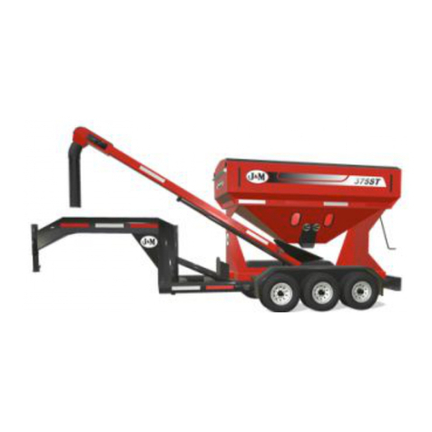
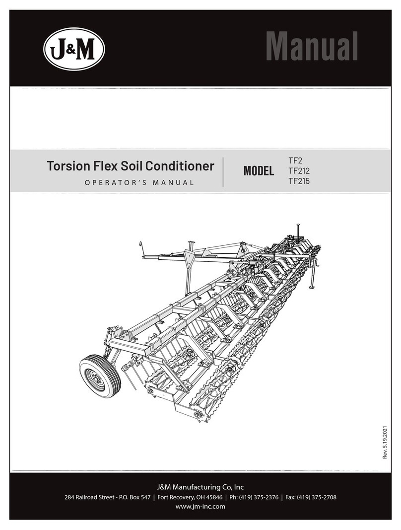
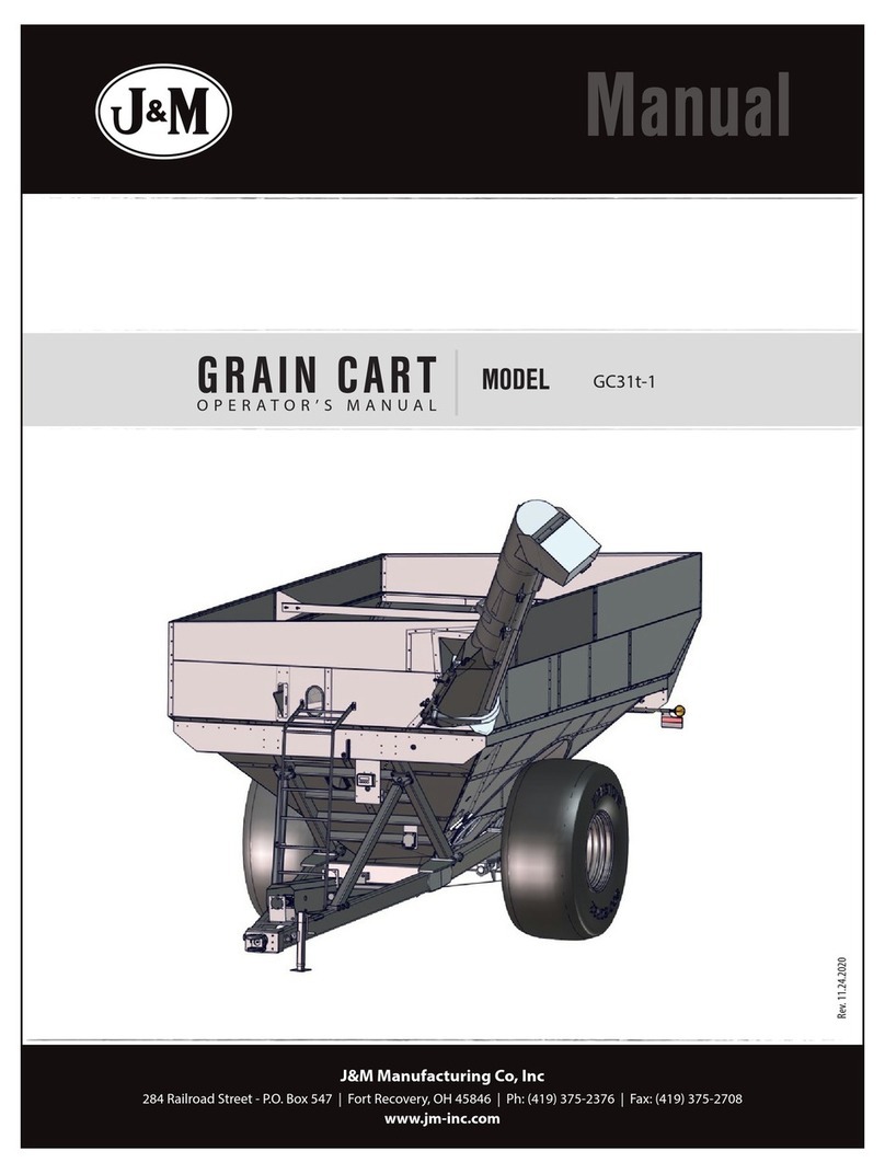
J&M GC31t-1 User manual

J&M

J&M GC31t-1 User manual

J&M 275-ST User manual

J&M

J&M 275-ST User manual

J&M 1522 User manual

J&M

J&M 1522 User manual

J&M TF2 User manual

J&M

J&M TF2 User manual

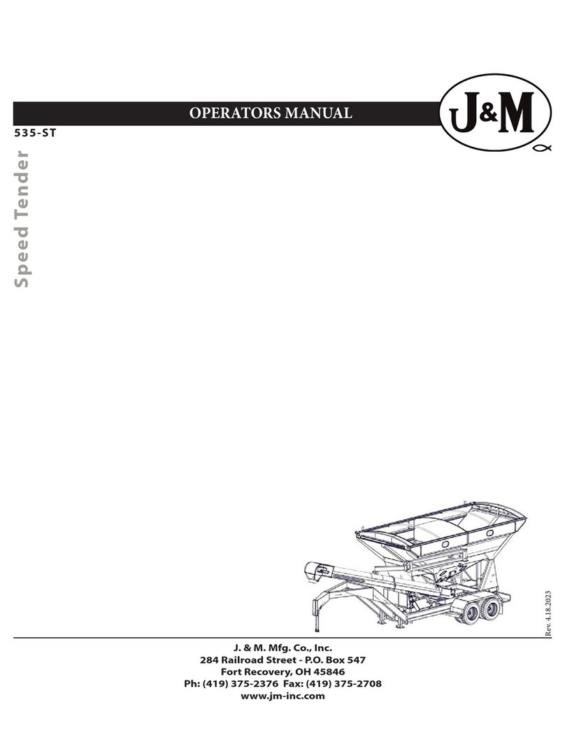
J&M Speed Tender 535-ST User manual

J&M

J&M Speed Tender 535-ST User manual

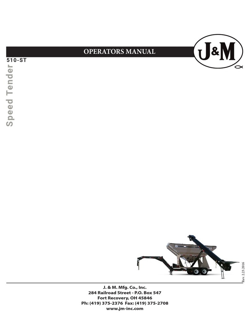
J&M 510-ST User manual

J&M

J&M 510-ST User manual

J&M NITRO-GRO 5010 User manual

J&M

J&M NITRO-GRO 5010 User manual

J&M 525 User guide

J&M

J&M 525 User guide

J&M 750 User manual

J&M

J&M 750 User manual

J&M 1522 User manual

J&M

J&M 1522 User manual

J&M HT-974 User manual

J&M

J&M HT-974 User manual

J&M 6018 User manual

J&M

J&M 6018 User manual

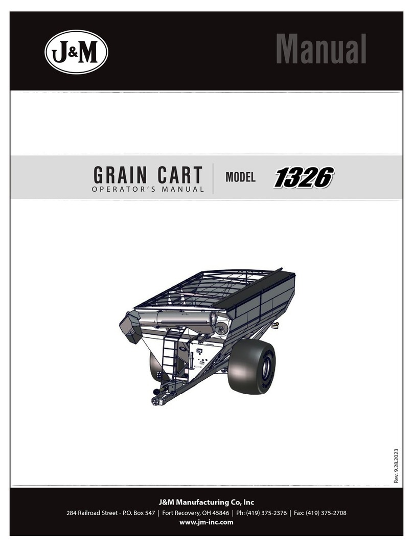
J&M 1326 User manual

J&M

J&M 1326 User manual

J&M Nitro Gro 5010 User manual

J&M

J&M Nitro Gro 5010 User manual

J&M X2431 User manual

J&M

J&M X2431 User manual

J&M 32 Series User manual

J&M

J&M 32 Series User manual

J&M SpeedTender LC290 User manual

J&M

J&M SpeedTender LC290 User manual

J&M 206270 User manual

J&M

J&M 206270 User manual

J&M Torsion Flex User manual

J&M

J&M Torsion Flex User manual

J&M 32 Series User manual

J&M

J&M 32 Series User manual

J&M SpeedTender 500ST User manual

J&M

J&M SpeedTender 500ST User manual

J&M Trail-Blazer TB-6000 User manual

J&M

J&M Trail-Blazer TB-6000 User manual

J&M nitro gro 6018 User manual

J&M

J&M nitro gro 6018 User manual

J&M 1012 User manual

J&M

J&M 1012 User manual

Popular Farm Equipment manuals by other brands

360 BANDIT KINZE 3000 installation instructions

360

360 BANDIT KINZE 3000 installation instructions

Duncan Enviro DD55 Original instructions

Duncan

Duncan Enviro DD55 Original instructions

Quick Attach QUICK POWER SCAPE Mini Operation & maintenance manual

Quick Attach

Quick Attach QUICK POWER SCAPE Mini Operation & maintenance manual

AfiMilk AfiAct II Installation

AfiMilk

AfiMilk AfiAct II Installation

GSi TopDry Construction manual

GSi

GSi TopDry Construction manual

GREAT PLAINS SPARTAN II Operator's manual

GREAT PLAINS

GREAT PLAINS SPARTAN II Operator's manual

GREAT PLAINS 605NT Maintenance manual

GREAT PLAINS

GREAT PLAINS 605NT Maintenance manual

Raven OmniSeed Quick reference guide

Raven

Raven OmniSeed Quick reference guide

APV LF 600 M1 operating manual

APV

APV LF 600 M1 operating manual

Mandam SAL DISC HARROW Operation manual

Mandam

Mandam SAL DISC HARROW Operation manual

SaMASZ KDT 180 Operator's manual

SaMASZ

SaMASZ KDT 180 Operator's manual

Roto-Mix Roto-Spread 532-16B Operation and parts manual

Roto-Mix

Roto-Mix Roto-Spread 532-16B Operation and parts manual

Raven VSN installation manual

Raven

Raven VSN installation manual

Major MJ30-560HD Operator's manual & parts list

Major

Major MJ30-560HD Operator's manual & parts list

aivituvin AIR 48 instruction manual

aivituvin

aivituvin AIR 48 instruction manual

MacDon A30-S Unloading and assembly instructions

MacDon

MacDon A30-S Unloading and assembly instructions

AGPRO AGTL105 Operation manual

AGPRO

AGPRO AGTL105 Operation manual

Headsight SHELBOURNE manual

Headsight

Headsight SHELBOURNE manual

manuals.online logo
manuals.online logoBrands
  • About & Mission
  • Contact us
  • Privacy Policy
  • Terms and Conditions

Copyright 2025 Manuals.Online. All Rights Reserved.