Timberwolf EPI22 User manual

EN
FR
PG
33
W415-1466 / 04.21.15
INSTALLER: LEAVE THIS MANUAL WITH THE APPLIANCE.
CONSUMER: RETAIN THIS MANUAL FOR FUTURE REFERENCE.
NEVER LEAVE CHILDREN OR OTHER AT RISK INDIVIDUALS ALONE WITH THE APPLIANCE.
INSTALLATION AND
OPERATING INSTRUCTIONS
1.14E
Wolf Steel Ltd., 24 Napoleon Rd., Barrie, ON, L4M 0G8 Canada /
103 Miller Drive, Crittenden, Kentucky, USA, 41030
Phone (705)721-1212 • Fax (705)722-6031 • www.timberwolffireplaces.com • ask@timberwolffireplaces.com
SAFETY INFORMATION
!WARNING
If the information in these instructions is not followed exactly,
a fire or explosion may result causing property damage,
personal injury or death. Improper installation, adjustment,
alteration, service or maintenance can cause injury or property
damage, bodily injury or even death. Please read entire
manual before you install and use your appliance.
- This appliance can be very hot when burning.
- Combustible materials such as firewood, wet clothing, etc. placed too
close can catch fire.
- Children and pets must be kept from touching the appliance when it is hot.
- The chimney must be sound and free of cracks. Before installing this unit,
contact the local building or fire authority and follow their guidelines.
- Operate only with the door tightly closed.
- Burn wood behind the log retainer directly on the firebricks.
- Do not use an elevated grate or otherwise raise the fire.
- At least 14 square inches (90 square centimeters) of outside air must be
admitted to the room or directly to the unit through a 4” (102mm) diameter
pipe.
- This appliance is designed to burn natural wood only. Higher efficiencies
and lower emissions generally result when burning air dried seasoned
hardwoods, as compared to softwoods or to green or freshly cut
hardwoods.
- Do not start a fire with chemicals or fluids such as gasoline, engine oil, etc.
- Do not burn trash or garbage, lawn clippings / waste, rubber, waste
petroleum products, paints or paint thinners / solvents, plastic, materials
containing asbestos, construction debris, railroad ties or treated wood,
manure or animal remains, salt water driftwood or salted materials,
unseasoned wood, coal, charcoal, coloured paper, cardboard, plywood or
particleboard.
- Do not let the appliance become hot enough for any part to glow red.
- KEEP THE STOVE TOP TEMPERATURE BELOW 700°F (371°C). Attempts to
achieve heat output rates that exceed design specifications can result in
steel distortion and damage.
$10.00
HOT GLASS WILL CAUSE
BURNS.
DO NOT TOUCH GLASS UNTIL
COOLED.
NEVER ALLOW CHILDREN TO
TOUCH GLASS.
!
WARNING
MODEL EPI22 MEETS THE 2015 U.S ENVIRONMENTAL PROTECTIONAGENCY (E.P.A.) CRIB WOOD EMISSION LIMITS FOR WOOD STOVES SOLD AFTER MAY
15, 2015, 40 C.F. R. PART 60. THESEAPPLIANCES HAVE BEEN TESTEDAND LISTED BY OMNI-TEST LABORATORIES, INC. TO STANDARDS: ULC-S628, UL1482.
EPI22
WOOD INSERT

W415-1466 / 04.21.15
EN
2
NOTE: Changes, other than editorial, are denoted by a vertical line in the margin.
TABLE OF CONTENTS
1.0 INSTALLATION OVERVIEW 3
2.0 INTRODUCTION 4
2.1 DIMENSIONS (COMPLETE WITH FLASHING) 5
2.2 SPECIFICATIONS 5
2.3 GENERAL INSTRUCTIONS 5
2.4 GENERAL INFORMATION 6
2.5 E.P.A. COMPLIANCE 7
2.6 RATING PLATE LOCATION 8
3.0 PRE-INSTALLATION PREPARATION 9
3.1 MINIMUM CLEARANCE TO COMBUSTIBLES 9
4.0 INSTALLATION 10
4.1 TYPICAL EXISTING MASONRY 11
4.2 FACTORY BUILT FIREPLACE 12
5.0 FINISHING 13
5.1 SECONDARYAIR TUBES 13
5.2 DOOR INSTALLATION 14
5.3 DOOR HANDLE INSTALLATION 14
5.4 BRICKS AND BAFFLES INSTALLATION 15
5.5 FLASHING INSTALLATION 16
5.6 BLOWER INSTALLATION 17
6.0 OPERATION 18
6.1 OPTIMUM BURN METHOD 19
6.2 AIR CONTROL 20
6.3 FIRE EXTINGUISHERS / SMOKE DETECTORS 20
6.4 FUEL 20
6.5 LIGHTING A FIRE 21
6.5.1 FLASH FIRE 21
6.5.2 EXTENDED FIRE 21
6.6 SMOKING 21
7.0 MAINTENANCE 22
7.1 ASH REMOVAL PROCEDURES 22
7.2 CREOSOTE FORMATION AND REMOVAL 22
7.3 RUNAWAY OR CHIMNEY FIRE 23
7.4 CHIMNEY CLEANING 23
7.5 DOOR REMOVAL 24
7.6 GLASS REPLACEMENT 24
7.7 CARE OF GLASS 25
7.8 CARE OF PLATED PARTS 25
7.9 BLOWER SERVICE OR REPLACEMENT 25
7.10 GASKETAND SHIELD REPLACEMENT 26
7.11 WOOD 27
8.0 REPLACEMENTS 28
9.0 TROUBLESHOOTING 30
10.0 WARRANTY 31

W415-1466 / 04.21.15
EN
3
1.0 INSTALLATION OVERVIEW
Rating plate, see
“RATING PLATE
INFORMATION”
section.
Blower, see “BLOWER INSTALLATION”
section.
Door, see “DOOR
AND HANDLE
INSTALLATION”
section.
Flashing, see “FLASHING
INSTALLATION” section.
Draft, see “AIR
CONTROL” section.

W415-1466 / 04.21.15
EN
4
2.0 INTRODUCTION
3.17E
!
WARNING
• THIS APPLIANCE IS HOT WHEN OPERATED AND CAN CAUSE SEVERE BURNS IF CONTACTED.
• ANY CHANGES OR ALTERATIONS TO THIS APPLIANCE OR ITS CONTROLS CAN BE DANGEROUS AND
IS PROHIBITED.
• Do not operate appliance before reading and understanding operating instructions. Failure to operate appliance
according to operating instructions could cause fire or injury.
• Before installing this appliance, contact the local building or fire authority and follow their guidelines.
• This appliance must be installed by a qualified installer.
• Risk of burns. The appliance should be turned off and cooled before servicing.
• Do not operate without fully assembling all components.
• Do not let the appliance become hot enough for any part to glow red.
• Do not install damaged, incomplete or substitute components.
• Risk of cuts and abrasions. Wear protective gloves and safety glasses during installation. Sheet metal edges
may be sharp.
• Children and adults should be alerted to the hazards of high surface temperature and should stay away to avoid
burns or clothing ignition.
• Young children should be carefully supervised when they are in the same room as the appliance. Toddlers,
young children and others may be susceptible to accidental contact burns. A physical barrier is recommended if
there are at risk individuals in the house. To restrict access to an appliance or stove, install an adjustable safety
gate to keep toddlers, young children and other at risk individuals out of the room and away from hot surfaces.
• Clothing or other flammable material should not be placed on or near the appliance. Objects placed in front of
the appliance must be kept a minimum of 48” (1219.2mm) away from the front face of the appliance.
• Due to high temperatures, the appliance should be located out of traffic and away from furniture and draperies.
• Ensure you have incorporated adequate safety measures to protect infants/toddlers from touching hot surfaces.
• Even after the appliance is out, the glass and/or screen will remain hot for an extended period of time.
• Check with your local hearth specialty dealer for safety screens and hearth guards to protect children from hot
surfaces. These screens and guards must be fastened to the floor.
• Any safety screen or guard removed for servicing must be replaced prior to operating the appliance.
• Under no circumstances should this appliance be modified.
• This appliance must not be connected to a chimney flue pipe servicing a separate solid fuel burning appliance.
• Do not operate the appliance with the glass door removed, cracked or broken. Replacement of the glass should
be done by a licensed or qualified service person.
• Do not strike or slam shut the appliance glass door.
• Only doors / optional fronts certified with the unit are to be installed on the appliance.
• Keep the packaging material out of reach of children and dispose of the material in a safe manner. As with all
plastic bags, these are not toys and should be kept away from children and infants.
• If the appliance is not properly installed, a house fire may result. Do not expose the appliance to the elements
(ex. rain, etc.) and keep the appliance dry at all times. Wet insulation will produce an odour when the appliance
is used.
• The chimney must be sound and free of cracks. Clean your chimney a minimum of twice a year and as required.
• Do not start a fire with chemicals or fluids such as gasoline, engine oil, etc.
• Your appliance requires periodic maintenance and cleaning. Failure to maintain your appliance may lead to
smoke spillage in your home.
• Lower emissions generally result when burning air dried seasoned hardwoods, as compared to softwoods or too
green or freshly cut hardwoods. Burning wet unseasoned wood can cause excessive creosote accumulation.
When this is ignited it can cause a chimney fire that may result in a serious house fire.
• This appliance is designed to burn natural wood only. Do not burn trash or garbage, lawn clippings / waste,
rubber, waste petroleum products, paints or paint thinners / solvents, plastic, materials containing asbestos,
construction debris, railroad ties or treated wood, manure or animal remains, salt water driftwood or salted
materials, unseasoned wood, coal, charcoal, coloured paper, cardboard, plywood or particleboard. Burning
these materials may result in release of toxic fumes or render the appliance ineffective and cause smoke.
• Burn wood directly on the firebricks. Do not elevate grate or otherwise raise the fire.
• Do not store wood within appliance installation clearances or within the space required for re-fueling and ash
removal.
• Ashes must be disposed in a metal container with a tight lid and placed on a non-combustible surface well away
from the home or structure until completely cool.
• Ensure clearances to combustibles are maintained when building a mantel or shelves above the appliance.
Elevated temperatures on the wall or in the air above the appliance can cause melting, discolouration or
damage to decorations, a T.V. or other electronic components.

W415-1466 / 04.21.15
EN
5
* As tested using the test method 28.
** Figures will vary considerably with individual conditions.
*** Wolf Steel Ltd. estimated realistic BTU/hr with hardwood logs and regular refueling.
Specifications EPI22
CHAMBER (D.W.H) 14 5/8" (371mm) x 20 7/8" (530mm) x 11 5/8" (295mm)
CAPACITY 1.9 ft3 (0.05m3 )
APPROX. AREA HEATED** 800-1800 ft2 (74m2 -167m2 )
MAXIMUM HEAT OUTPUT *** 65,000 BTU/Hr
HEAT OUTPUT* 12,084 -36,976 BTU/Hr
DURATION LOW FIRE* 8 Hours
WEIGHT w/o BRICKS 225 lbs (102kg)
WEIGHT OF BRICKS 60 lbs (27kg)
AB
MIN DEPTH 4" (102mm) 14" (356mm)
MAX DEPTH 7 1/2" (191mm) 17 1/2" (445mm)
2.1 DIMENSIONS (COMPLETE WITH FLASHING)
2.2 SPECIFICATIONS
31"
787mm
20"
508mm
43" 1092mm
21 3/4"
522mm
10 1/2"
267mm
14"
356mm
17 1/2"
445mm
4"
102mm
7 1/2"
191mm
25 3/8" 645mm
A
B
2.3 GENERAL INSTRUCTIONS
4.7
ALL WIRING SHOULD BE DONE BY A QUALIFIED ELECTRICIAN AND SHALL BE IN COMPLIANCE WITH
LOCAL CODES. IN THE ABSENCE OF LOCAL CODES, USE THE CURRENT CSA22.1 CANADIAN
ELECTRIC CODE IN CANADA OR THE CURRENT NATIONAL ELECTRIC CODE ANSI/NFPA NO. 70 IN
THE UNITED STATES.
THIS APPLIANCE HAS NOT BEEN TESTED WITH ANY VENTED OR UNVENTED GAS LOG SET. TO
REDUCE RISK OF FIRE OR PREVENT INJURY, DO NOT INSTALL A VENTED OR UNVENTED GAS LOG
SET INTO THE APPLIANCE.
BURNING YOUR UNIT WITH THE ASH DUMP DOOR OPEN OR AJAR CREATES A FIRE HAZARD THAT
MAY RESULT IN DISCOLOURATION TO THE GOLD PLATED DOOR, INTERNAL DAMAGE TO THE
APPLIANCE OR A HOUSE CHIMNEY FIRE.
DO NOT CONNECT THIS APPLIANCE TO A CHIMNEY FLUE SERVING ANOTHER APPLIANCE.
THIS APPLIANCE AND IT’S COMPONENTS ARE DESIGNED TO BE INSTALLED AND OPERATED AS A
SYSTEM. ANY ALTERATION TO OR SUBSTITUTION FOR ITEMS IN THIS SYSTEM, UNLESS ALLOWED
BY THESE INSTALLATION INSTRUCTIONS, WILL VOID THE LISTING AND MAY VOID THE PRODUCT
WARRANTY. IT MAY ALSO CREATE A HAZARDOUS INSTALLATION. READ THROUGH THESE
INSTRUCTIONS THOROUGHLY BEFORE STARTING YOUR INSTALLATION AND FOLLOW THEM
CAREFULLY THROUGHOUT YOUR PROJECT.
!
WARNING
* A and B are adjustable in 3/8" (9.5mm) increments (see min max below).

W415-1466 / 04.21.15
EN
6
2.4 GENERAL INFORMATION
• Before beginning your installation, consult with your local building code agency or fire officials and
insurance representative to ensure compliance.
• Non-toxic smoke will be emitted during the paint curing process, to help dissipate the smoke open a
window near the appliance.
• Remove any dust or debris off the top of the appliance before firing the appliance as the paint will
become soft as the appliance heats up and will harden as the appliance cures. To cure the paint on
your appliance burn your appliance moderately hot during the first few fires.
• To keep the gasket from sticking to the appliance as the paint is curing, periodically open the door
every 5-10 minutes.
• For the first two weeks use generous amounts of fuel and burn the appliance with the damper wide
open for an hour as the appliance goes through a process of eliminating moisture in the steel and
firebricks. The initial heat output will be reduced while the moisture is bring drawn from the appliance
and it will be necessary to build several hot fires to remove this moisture. DURING THIS PROCESS
DO NOT OVERFIRE THE APPLIANCE. REDUCE THE AMOUNT OF AIR COMING INTO THE
APPLIANCE IF THE APPLIANCE OR CHIMNEY BECOMES RED.
Your appliance was specifically designed to meet the 2015 U.S.A. EPA particulate emission standards and
have been extensively tested in Canadian and American laboratories. This system is the most efficient, simple
and trouble free we know and works as follows:
Your appliance is the exact duplication of the clean-burning technology found in all Timberwolf® EPAcertified
freestanding stoves. External modifications have been made to allow its installation as a “functional insert” with a heat
circulating blower system and a means of enclosing the solid fuel burning fireplace cavity for greater heating efficiency.
Your appliance must be installed only into a solid fuel burning fireplace that is at least 14” (356mm) deep 25 7/8”
(657mm) wide and 22” (559mm) high with an approved lined chimney at least 15 feet high (4.6m) and a hearth of 18”
(457mm). This minimum recess can only be achieved if the opening height is sufficient enough to allow the connector
to fit under the noncombustible facing. The appliance and chimney must be constructed in accordance with all national
and local building code standards.
The chimney vent system used on your wood burning appliance should be designed with the least amount of
restriction possible to enable the exhaust products to easily flow through it. Chimney vent systems that are too
short or too long can also have an adverse affect on the flow of exhaust through it. The wood burning appliance
and chimney vent system also require a sufficient supply of combustion air not only to support the combustion in the
combustion chamber but to replace the exhaust leaving it so it can flow freely
up through the vent system and out into the atmosphere. It is the correct
balance of combustion air and the chimney vent system that will ensure the
appliance provides you with its optimum performance.
Secondary air from the rear intake opening travels up the back in the
secondary air housing to the manifold located across the top and flows out
laterally to oxidize the gases below the smoke exit.
The lower combustion chamber is lined with high temperature firebricks on
2 sides, the back and across the bottom, with a layer of fibre baffles at the
top to maintain a high temperature in the combustion chamber so that gases
mixing with the preheated air from the secondary air manifold tube are easily
ignited and burned. The appliance sides and back are shielded to direct the
heat upwards and forwards into the room.
Be sure to provide sufficient combustion air. There are many other
appliances in your home competing for air such as: a kitchen range hood,
forced air heating devices or a bathroom exhaust fan.
AIR INLET PATH
EXHAUST PATH

W415-1466 / 04.21.15
EN
7
We suggest that our woodburning hearth products
be installed and serviced by professionals who are
certified in the U.S. by the National Fireplace
Institue® (NFI) as NFI Woodburning Specialists or
who are certified in Canada by
Wood Energy Technical
Training (WETT).
Expansion / contraction noises during heating up and cooling down cycles are normal and to be expected.
After extended periods of non-operation such as following a vacation or a warm weather season, the appliance
may emit a slight odour for a few hours. This is caused by dust particles on the firebox burning off. Open a
window to sufficiently ventilate the room.
2.5 E.P.A. COMPLIANCE
CALIFORNIA PROP 65 WARNING:
Use of this product may produce smoke which contains chemicals known to the State of California to cause
cancer, birth defects, or other reproductive harm.
If you experience smoking problems, you may need to open a door, a window or otherwise provide some
method of supplying combustion air to the appliance.

W415-1466 / 04.21.15
EN
8
2.6 RATING PLATE LOCATION
INSTALL AND USE ONLY IN ACCORDANCE WITHTHE
MANUFACTURER’S INSTRUCTIONSAND LOCALBUILDING CODES.
MINIMUM CEILING HEIGHT: 7FT (2.13m)
HEARTH EXTENSION / FLOOR PROTECTION: MUST BE
NON-COMBUSTIBLE AND EXTEND 22" IN FRONTOF THE
INSERTAND 8" ON BOTH SIDES WITHA MINIMUM
THICKNESS OF .500" (K=0.84)
CHIMNEY TYPE: MINIMUM 6” (152mm) DIAMETER APPROVED
RESIDENTIAL TYPE FOR MOBILE HOME USEACHIMNEY
LISTED TO ULC S629 IN CANADAOR UL 103HTIN THE USA.
DO NOT OBSTRUCT SPACE UNDER HEATER.
SPECIAL METHODSARE REQUIRED WHEN PASSING A
CHIMNEY THROUGHAWALLOR CEILING. SEE INSTRUC-
TIONS AND BUILDING CODES.
DO NOT CONNECT THIS UNITTOACHIMNEY FLUE SERVING
ANOTHER APPLIANCE.
FUEL: FOR USE WITH SOLID WOOD FUEL ONLY. DO NOT
USE GRATE OR ELEVATE FIRE. BUILD WOOD FIRE DIRECTLY
ON HEARTH.
WARNING: RISK OF SMOKE SPILLAGE. OPERATE ONLY WITH
DOOR FULLY CLOSED.
REPLACE GLASS ONLY WITH CERAMIC GLASS.
DO NOT OVERFIRE. IF HEATER OR CHIMNEY CONNECTORS
GLOW,YOU ARE OVERFIRING. INSPECTAND CLEAN
CHIMNEY FREQUENTLY. UNDER CERTAIN CONDITIONS OF
USE CREOSOTE BUILD-UP MAY OCCUR RAPIDLY.
DANGER: RISK OF ELECTRICAL SHOCK. DISCONNECT
POWER BEFORE SERVICING UNIT.
INSERT: INSTALLAND USE ONLY IN SOLID FUEL BURNING
FIREPLACES. DO NOT REMOVE BRICKS OR MORTAR FROM
SOLID FUEL BURNING FIREPLACE. INSTALL WITHA
POSITIVE FLUE CONNECTORAND FACEPLATE.
CONTACT LOCAL BUILDING FIRE OFFICIALS ABOUT RESTRIC-
TIONS AND INSTALLATION INSPECTION IN YOUR AREA.
A MINIMUM CLEARANCE OF 18” (457mm)TO THE CHIMNEY
CONNECTOR MAY BE REQUIRED BY THEAUTHORITY
HAVING JURISDICTION.
POUR INSTALLATION ET UTILISATION CONFORMÉMENT
AUX INSTRUCTIONS DU FABRICANTETAUX CODES
LOCAUX DU BÂTIMENT.
HAUTEUR DE PLAFOND MINIMAL: 7PI (2,13m).
BASE DE PROTECTION/PROTECTION DE PLANCHER :
DOIT ÊTRE DE NATURE INCOMBUSTIBLE ET SE
PROLONGER DE 22" À L’AVANT DE L’ENCASTRÉ ET 8"
SUR LES CÔTÉS, ETAVOIR UNE ÉPAISSEUR MINIMALE
DE 0,500" (K = 0,84).
TYPE DE CHIMNÉE: DIAMÈTRE MINIMAL DE 6” (152mm)
APPROUVÉE POUR USAGE RÉSIDENTIEL. MAISON
MOBILE EMPLOYEZ UNE CHEMINÉE HOMOLOGUÉE ULC
S629 AU CANADAOU UL 103HTAUX ÉTATS-UNIS.
NE RIEN ENTREPOSER SOUS L’APPAREIL.
DES MÉTHODES SPÉCIALES SONT REQUISES
LORSQU’UNE CHEMINÉE TRAVERSE UN MUR OU UN
PLAFOND. VOIR LES INSTRUCTIONS ET LES CODES DU
BÂTIMENT.
NE PAS RACCORDER À LA CHEMINÉE D’UN AUTRE
APPAREIL.
COMBUSTIBLE: POUR USAGE AVEC LE BOIS
SEULEMENT. N’UTILISEZ PAS DE CHENETOU NE
SURÉLEVEZ PAS LE BOIS. PRÉPAREZ LE FEU DIRECTE-
MENT SUR L’ÂTRE.
AVERTISSEMENT: RISQUE D’ÉCHAPPEMENTDE FUMÉE.
TENIR LA PORTE FERMÉE LORSQUE LE POÊLE
FONCTIONNE. REMPLACEZ LA VITRE PAR UNE VITRE EN
CÉRAMIQUE SEULEMENT.
NE SURCHAUFFEZ PAS L’APPAREIL. SI L’APPAREIL OU
LES RACCORDS ROUGEOIENT, L’APPAREIL
SURCHAUFEE. INSPECTEZ ET NETTOYEZ LACHEMINÉE
FRÉQUEMMENT. DANS CERTAINES CONDITIONS, DES
DÉPÔTS DE CRÉOSOTE PEUVENT SE FORMER
RAPIDEMENT.
DANGER: RISQUE DE SECOUSSE ÉLECTRIQUE.
DÉBRANCHEZ AVANT DE PROCÉDER À L’ENTRETIEN.
ENCASTRÉ: INSTALLEZ ET UTILISEZ SEULEMENT DANS
UN FOYER À COMBUSTIBLE SOLIDE. NE RETIREZ PAS DE
MORTIER, NI BRIQUES DU FOYER À COMBUSTIBLE
SOLIDE.
INSTALLEZ AVEC UNE GAINE CONFORME ET UNE
PLAQUE DE RECOUVREMENT.
RENSEIGNEZ-VOUS AUPRÈS DES AUTORITÉS LOCALES
DU BÂTIMENT ET DU SERVICE DES INCENDIESAU SUJET
DES RESTRICTIONS ET DES INSPECTIONS
D’INSTALLATION DANS VOTRE RÉGION.
UN DÉGAGEMENT MINIMAL DE 18” (457mm) JUSQU’AU
RACCORD DE LA CHEMINÉE PEUTÊTRE EXIGÉ PAR
L’AUTORITÉ AYANT JURIDICTION.
W385-2029
DATE CODE / DE DATE
TI-2201
LISTED SOLID FUEL BURNING FIREPLACE INSERT
TESTED TO: / TESTÉ SELON :
UL1482 - 1996 / ULC S628 - 1993
MODEL / MODÈLE: 2201
ENCASTRÉ ÀCOMBUSTIBLESOLIDEHOMOLOGUÉ
CAUTION:
ATTENTION:
HOTWHILE INOPERATION. DONOT
TOUCH.KEEPCHILDRENCLOTHINGAND
FURNITUREAWAY. CONTACTMAYCAUSE
SKINBURNS.
QUAND L’APPAREILFONCTIONNE, LA
SURFACE DEVIENT CHAUDE. NE PAS
TOUCHER. TENIR LES ENFANTS, LES
VÊTEMENTS ET LES MEUBLES À
L’ÉCART. LE CONTACT PEUT CAUSER
DES BRÛLURES À LAPEAU.
A
BC
D
E
F
G
WOLFSTEELLTD.
24 NAPOLEON ROAD,
BARRIE, ON, L4M 0G8 CANADA
NACGUANGZHOUP.R.C.
NO.69 HEFENG ROAD,
GUANGZHOU,CHINA
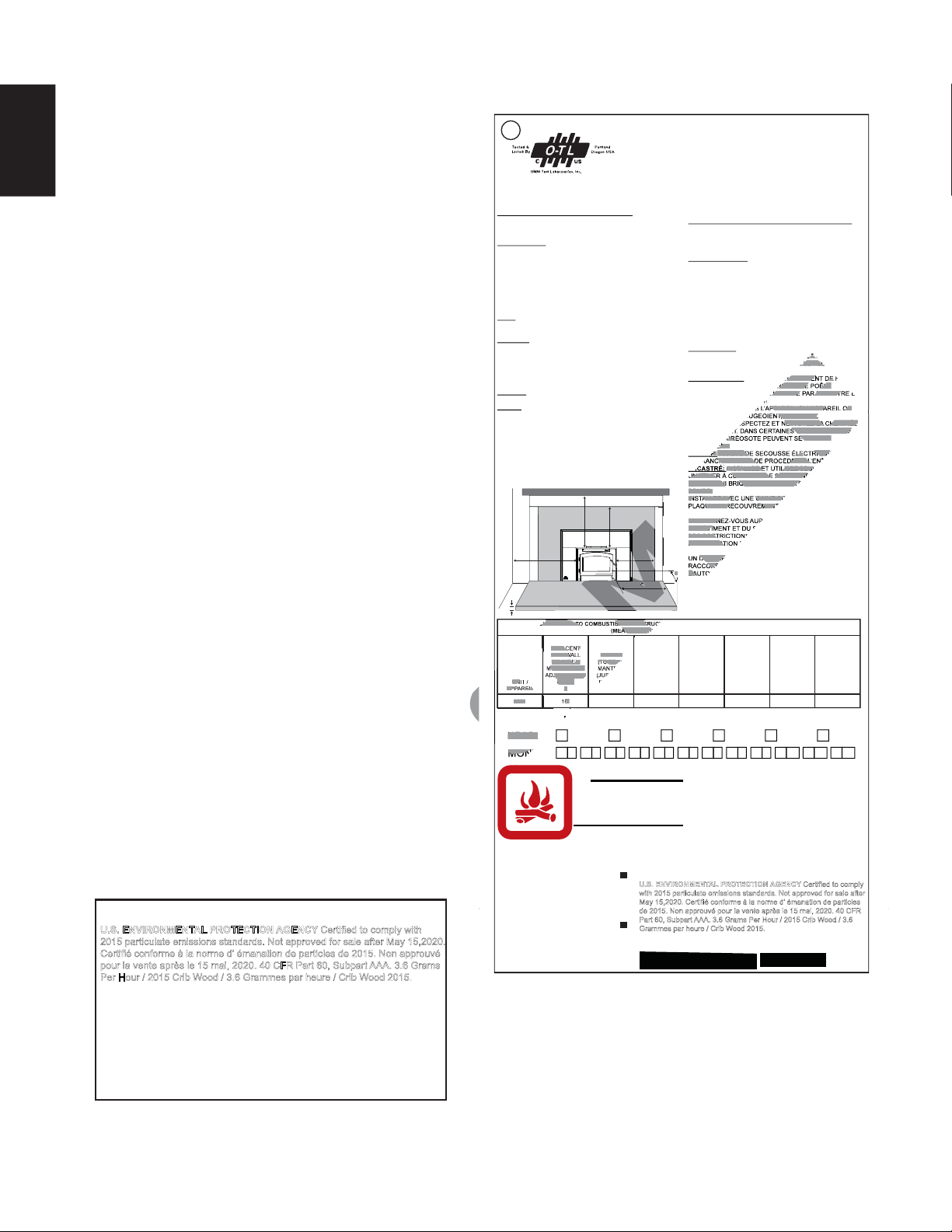
CLEARANCE TO COMBUSTIBLE CONSTRUCTION / DÉGAGEMENTS AUX MATÉRIAUX COMBUSTIBLES:
(MEASURED TO UNIT / À PARTIR DE L’APPAREIL)
UNIT /
APPAREIL
ADJACENT
SIDE WALL
(TO SIDE) /
MUR LATÉRAL
ADJACENT (AU
CÔTÉ)
A
MANTLE
(TO TOP) /
MANTEAU
(JUSQU’AU
DESSUS)
B
TOP FACING
(TO TOP) /
HAUT DE LA
FAÇADE
(JUSQU’AU
DESSUS)
C
SIDE FACING
(TO SIDE) /
CÔTÉ DE LA
FAÇADE (AU
COTÉ)
D
MINIMUM
HEARTH
EXTENSION /
BASE DE
PROTECTION
MINIMALE
E
MINIMUM
HEARTH
THICKNESS /
ÉPAISSEUR
MINIMALE DE LA
BASE DE
PROTECTION
F
MINIMUM
HEARTH SIDE
EXTENSION /
BADE DE
PROTECTION
LATÉRALE
MINIMALE
G
2201 8”1”22”10”22”30”16”
REPORT NO. 415-S-08-2
MANUFACTURE DATE: / DATE DE FABRICATION:
YEAR: 2015 2016 2017 2018
MONTH: 2019 2020
243658710912111
U.S. ENVIRONMENTAL PROTECTION AGENCY Certified to comply
with 2015 particulate emissions standards. Not approved for sale after
May 15,2020. Certifié conforme à la norme d’ émanation de particles
de 2015. Non approuvé pour la vente après le 15 mai, 2020. 40 CFR
Part 60, Subpart AAA. 3.6 Grams Per Hour / 2015 Crib Wood / 3.6
Grammes par heure / Crib Wood 2015.
For rating plate location, see “INSTALLATION
OVERVIEW” section.
NOTE: The rating plate must remain with
the appliance at all times. It must not be
removed.
This illustration is for reference only. Refer to the
rating plate on the appliance for accurate information
S
SAMPLE
SAMPLE
ET O
Z LE FEU
HAPPEMENT DE
RSQUE LE POÊLE
LA VITRE PAR UNE VIT
T.
PPAREIL. SI L’APPAREIL OU
T, L’APPAREIL
NETTOYEZ LACHEMINÉE
S CONDITIONS, DES
CRÉOSOTE PEUVENT SE FORMER
ENT.
R:
RISQUE DE SECOUSSE ÉLECTRIQUE
L
CHEZ AVANT DE PROCÉDER À L’ENT
INSTALLEZ ET UTILISEZ SEUL
PL
UN FOYER À COMBUSTIBLE SOLIDE. NE
MORTIER, NI BRIQUES DU FOYER À C
SOLIDE.
INSTALLEZ AVEC UNE GAINE CO
UE DE RECOUVREMENT
RENSEIGN
DU BÂTIM
DES REST
D’INSTALLAT
DÉGAGE
RACCORD
L’AU
M
M
P
MP
AM
AM
AM
AM
M
M
M
M
AM
M
M
M
D
E
G
M
M
M
M
M
SA
AM
CLEARANCE TO COMBUSTIBLE CONSTR
ASURED TO
M
AM
SA
UN
APPAREIL
ADJACENT
SIDE WALL
(TO SIDE) /
MUR LATÉRAL
JACENT (AU
CÔTÉ)
A
MANTLE
(TO TOP)
TE
2201
6”
SAM
M
M
M
M
M
M
M
M
M
M
M
M
M
M
M
M
M
M
M
M
M
M
M
M
M
M
M
M
YEAR:
MON
This wood appliance needs periodic inspection and repair for proper operation.
Consult the owner’s manual for further information. it is against federal
regulations to operate this wood appliance in a manner inconsistent with the
operating instructions in the owner’s manual. / Cet appareil au bois doit faire
l'objet d'une inspection et d'un entretien périodiques pour un fonctionnement
adéquat. Consultez le manuel d'instructions pour plus d'information. Les
règlements fédéraux interdisent d'utiliser cet appareil de chauffage d'une
manière allant à l'encontre des instructions de fonctionnement contenues dans
ce manuel.
U.S. ENVIRONMENTAL PROTECTION AGENCY Certified to comply with
2015 particulate emissions standards. Not approved for sale after May 15,2020.
Certifié conforme à la norme d’ émanation de particles de 2015. Non approuvé
pour la vente après le 15 mai, 2020. 40 CFR Part 60, Subpart AAA. 3.6 Grams
Per Hour / 2015 Crib Wood / 3.6 Grammes par heure / Crib Wood 2015.
W385-2050
MODEL / MODÈLE: EPI22

W415-1466 / 04.21.15
EN
9
3.0 PRE-INSTALLATION PREPARATION
Clean all ashes out of the inside of the existing fireplace opening. Make sure that the chimney and fireplace are
free of cracks, loose mortar, creosote deposits, blockage or other signs of deterioration. If necessary, have any
repair work done by a qualified professional before installing the insert.
Do NOT remove bricks or mortar from the fireplace. In case of an outside air inlet or ash dump, fill with fiber-
glass insulation. Adhere to minimum clearances as illustrated.
Combustible material must not protrude more than 1" (25mm) to the side of the insert or between the mantel
and the top of the insert.
MINIMUM CLEARANCES
ASidewall 16" (406mm)
BMantel 30" (762mm)
CTop facing 22" (559mm)
DSide facing 10" (254mm)
EHearth (front) 22" (559mm)
FHearth (side) 8" (203mm)
GIn front of
insert 48" (1219mm)
MINIMUM APPLIANCE SIZE
HWidth (rear) 25 7/8" (657mm)
IWidth (front) 25 7/8" (657mm)
JHeight (front) 22" (559mm)
KHeight (rear) 22" (559mm)
LDepth 14" (356mm)
MHearth depth 22" (559mm)
NHearth width 41 3/8" (1051mm)
OFacing width 45 3/8" (1153mm)
PFacing height 42 5/8" (1083mm)
QMantel 50 5/8" (1286mm)
A
D
C
B
E
G
F
P
M
Q
N
J
K
L
H
I
O
3.1 MINIMUM CLEARANCE TO COMBUSTIBLES
HEARTH EXTENSION / FLOOR
PROTECTION:
Must be non-combustible and extend
18" (457mm) in front of the insert and 8"
(203mm) on both sides with a minimum
thickness of 1" (25mm) and a thermal
conductivity factor (K) 0.84.

W415-1466 / 04.21.15
EN
10
4.0 INSTALLATION
68.3A
!
WARNING
WEAR GLOVES AND SAFETY GLASSES FOR PROTECTION.
CAREFULLY FOLLOW THE INSTRUCTIONS FOR ASSEMBLY OF THE PIPE AND OTHER PARTS NEEDED TO INSTALL THE
APPLIANCE. FAILURE TO DO SO MAY RESULT IN A FIRE, ESPECIALLY IF COMBUSTIBLES ARE TOO CLOSE TO THE
APPLIANCE OR CHIMNEY AND AIR SPACES ARE BLOCKED, PREVENTING THE FREE MOVEMENT OF COOLING AIR.
DO NOT DRAW OUTSIDE AIR FROM GARAGE SPACES. EXHAUST PRODUCTS OF GASOLINE ENGINES ARE HAZARDOUS.
DO NOT INSTALL OUTSIDE AIR DUCTS SUCH THAT THE AIR MAY BE DRAWN FROM ATTIC SPACES, BASEMENTS OR
ABOVE THE ROOFING WHERE OTHER HEATING APPLIANCES OR FANS AND CHIMNEYS EXHAUST OR UTILIZE AIR.
THESE PRECAUTIONS WILL REDUCE THE POSSIBILITY OF APPLIANCE SMOKING OR AIR FLOW REVERSAL. THE
OUTSIDE AIR INLET MUST REMAIN CLEAR OF LEAVES, DEBRIS ICE AND/OR SNOW. IT MUST BE UNRESTRICTED WHILE
APPLIANCE IS IN USE TO PREVENT ROOM AIR STARVATION WHICH CAN CAUSE SMOKE SPILLAGE AND AN INABILITY
TO MAINTAIN A FIRE. SMOKE SPILLAGE CAN ALSO SET OFF SMOKE ALARMS.
NEGATIVE PRESSURE WITHIN YOUR HOME MAY INADVERTENTLY AFFECT YOUR APPLIANCE.
TO PREVENT CONTACT WITH SAGGING OR LOOSE INSULATION, THE APPLIANCE MUST NOT BE INSTALLED
AGAINST VAPOUR BARRIERS OR EXPOSED INSULATION. LOCALIZED OVERHEATING COULD OCCUR AND A FIRE
COULD RESULT.
DO NOT USE MAKESHIFT COMPROMISES DURING INSTALLATION. DO NOT BLOCK OR RESTRICT AIR, GRILLE OR
LOUVRE OPENINGS. DO NOT ADD A HOOD.
KEEP HAND TOOLS IN GOOD CONDITION, SHARPEN CUTTING EDGES AND MAKE SURE TOOL HANDLES ARE
SECURE.
ALWAYS MAINTAIN THE MINIMUM AIR SPACE REQUIRED TO THE ENCLOSURE TO PREVENT FIRES.
It is extremely important that your appliance be installed according to the manufacturer's specifications. The
manufacturer's installation instructions and specified clearances should always be followed in accordance with
local and national codes. In Canada the CSA B365 and the CSA C22.1 installation codes are to be followed. In
the USA the ANSI NFPA 70 and ANSI NFPA 211 installation codes are to be followed.
Chimney and liner must be in good condition and kept clean.

W415-1466 / 04.21.15
EN
11
4.1 TYPICAL EXISTING MASONRY
You can install your appliance using your existing masonry chimney. To do
so, follow the guidelines below. If you are using a masonry chimney, it
is important that it be built in compliance with the specifications of the
Building Code in your region. It must normally be lined with fire clay
bricks, metal or clay tiles sealed together with fire cement. (Round
flues are the most efficient).
62.2
FOLLOW MANUFACTURER’S
INSTRUCTIONS FOR
MAXIMUM LINER EXTENSION
ABOVE CHIMNEY
FLOOR
PROTECTOR
DAMPER PLATE
REMOVED OR
FASTENED IN OPEN
POSITION
SEAL WITH NON-
COMBUSTIBLE
MATERIAL
MASONRY
CHIMNEY MUST
HAVE
STRUCTURAL
INTEGRITY LISTED
CHIMNEY
LINER
A. Remove the fireplace damper or fasten it permanently open.
* We recommend the following method of sealing off the damper area around the liner.
B. * Measure the throat of the fireplace and mark this shape on a piece of 24 gauge sheet metal (flue
cover); cut a six-inch (6.75" / 171mm) hole to lie directly below the fireplace flue opening.Allow two
inches of material for a flange on all sides and cut to these measurements. Bend down the flanges. If you
have never done this before, it might be a good idea to make a cardboard pattern and test it first. Fasten
this flue cover in position as high as possible with two masonry screws per side through the flanges into
the fireplace.
In Canada: Install a listed 6" (152mm) diameter flexible stainless steel liner from the top of the chimney to the
insert flue collar. Attach a stainless steel liner connector or elbow to the liner and insert onto the flue collar. Fasten
with three screws. Secure the top of the liner to the chimney cap using a liner support and chimney flashing. Cap
the top of the chimney liner assembly using an approved rain cap.
In the United States: While it is not required, it is recommended that a chimney liner be installed that is
continuous from the insert to the top of the chimney, particularly when the insert is installed in a basement. For
this type of connection, use the “In Canada” installation instructions above.
If a continuous liner is not installed, a “direct flue connection” must be made. The direct flue connection requires a
non-combustible connector that extends from the insert into the chimney flue liner and also that the installed flue
cover be sealed below the entry point of the connector to prevent dilution of combustion products in the chimney
flue with air from inside the house. Cap the top of the chimney using an approved rain cap.
The following installation requirements must be observed when installing solid fuel burning inserts into factory
built fireplaces.

W415-1466 / 04.21.15
EN
12
4.2 FACTORY BUILT FIREPLACE
The following installation requirements must be observed when installing solid fuel burning inserts into factory
built fireplaces.
A. The factory built fireplace must be listed per UL 127 or ULC S610.
B. Clearances to any combustible material surrounding this insert as identified must be followed. These
clearance requirements supersede any pre-existing facing material clearances listed for the factory
built fireplace.
C. Installation must include a full height listed chimney liner meeting HT requirements (2100°F/1149°C)
as required in UL 1777 (U.S.) or ULC S635 (Canada). The liner must be securely attached to the insert
flue collar and the chimney top.
D. Means must be provided to prevent room air passage to the chimney cavity of the fireplace. This may
be accomplished by sealing the damper area around the chimney liner, or sealing the appliance front.
E. The air flow within and around the appliance shall not be altered by the installation of the insert (i.e.
no louvres or cooling air inlet or outlet ports are blocked), unless specifically tested as such for each
factory built fireplace manufacturer and model line. NOTE: Using a louvered face plate (surround)
complies with this requirement.
F. Alteration of the appliance in any manner is not permitted with the following exceptions;
A. External trim pieces which do not affect the operation of the appliance may be removed providing
they can be stored on or within the fireplace for reassembly if the insert is removed.
B. The chimney damper may be removed to install the chimney liner.
G. Circulating air chambers (i.e. in a steel fireplace liner or metal heat circulator) shall not be blocked.
H. Means must be provided for removal of the insert to clean the chimney flue.
I. Inserts that project in front of the fireplace must be supplied with appropriate support means.
J. A permanent metal warning label must be attached to the back of the fireplace stating that the fireplace
must be restored to its original condition for safe use without the insert. 80.2B

W415-1466 / 04.21.15
EN
13
5.0 FINISHING
5.1 SECONDARY AIR TUBES
A. Start at the back working forwards, install the secondary
air tube by inserting the tube into the hole,
as illustrated in “A”.
B. Slide the tube into the opposite hole.
With the holes on the secondary air
tube pointing forward, align the
tube with the tube retainer
and insert the cotter
pin, as illustrated
in“B”.
C. Spread the cotter pin
to retain.
NOTE: There are 4
secondary air tubes. One of
the tubes has larger holes.
This tube is to be located
closest to the front of the
appliance, as illustrated in
“C”.
B
COTTER PIN
TUBE
RETAINER
C
A
HOLE

W415-1466 / 04.21.15
EN
14
5.2 DOOR INSTALLATION
Hang the door using the hinge pins supplied.
5.3 DOOR HANDLE INSTALLATION
DOOR
HANDLE
NUT
DOOR HANDLE
LATCH LOCK
WASHER
DOOR
SPACER
SPRING
WASHER
FRONT VIEW
NOTE: Position of
door handle latch.
98.1
NOTE: DOOR MAY NOT BE AS
ILLUSTRATED
Twist the large wire handle over the end of the handle rod. Twist the smaller wire handle over the end of the air control rod
above the door.

W415-1466 / 04.21.15
EN
15
!
WARNING
5.4 BRICKS AND BAFFLES INSTALLATION
AAAA
AAAA
AAAA
AAAA
A
AAA
E
C
B
A
D
D
E
With the appliance and chimney installation completed, move the bricks into place as illustrated below.
A. Install the bottom nine (A) bricks and one (B) brick, working from the back of the appliance forward as
illustrated.
B. Install four (A) bricks along both sides of the appliance.
C. Install the four (A) bricks and one (C) brick along the back wall by pivoting the bricks up under the brick
retainer. NOTE: Place narrow (C) brick in centre.
D. Install two (D) bricks along the front of the appliance below the ledge at the bottom of the door
opening.
E. Carefully pivot two (E) fibre baffles up onto the secondary air tubes as illustrated. Ensure that the top
baffles are pushed all the way to the rear of the firebox, leaving a minimum of a 1 inch gap along the
front. This will allow the flue gases to escape the firebox. Ensure overlap joint is tight.
BAFFLE
SECONDARY
AIR TUBES
OVERLAP
JOINT
OPERATION OF THE APPLIANCE WITHOUT THE BAFFLES CAN RESULT IN EXCESSIVE TEMPERA-
TURES THAT COULD DAMAGE THE APPLIANCE, CHIMNEY AND THE SURROUNDING ENCLO-
SURE.

W415-1466 / 04.21.15
EN
16
5.5 FLASHING INSTALLATION
A. With the flashing close to its final position, assemble sides as illustrated using the supplied fasteners.
B. The flashing position on the insert is adjustable, allowing for varying fireplace cavity and/or hearth
depths. Engage the tabs on the assembled side flashings into the appropriate slots on the insert for
the desired final location.
C. Adjust the blower chute tightly against the flashing and secure it in place.
D. Insert the top piece as illustrated, then bolt together using the screws, lock washers and weldnuts
provided.
E. Slide the appliance back into position.
BLOWER
CHUTE

W415-1466 / 04.21.15
EN
17
!
WARNING
5.6 BLOWER INSTALLATION
Drywall dust will penetrate into the blower bearings, causing irreparable damage. Care must be taken to
prevent drywall dust from coming into contact with the blower or its compartment. Any damage resulting from
this condition is not covered by the warranty policy. Use of the blower increases the output of heat.
This blower is thermally activated. Depending on the intensity of the fire, the blower will start 15-30 minutes
after lighting. The thermal switch for the appliance is affixed to an adjustable bracket, which should be
positioned so it is in contact with the blower housing as illustrated.
For shipping purposes the blower housing has
been stored within the firebox. We recommend
removing the door prior to installing the blower.
A. Remove the two screws securing the
cover and set aside.
B. Engage the clips onto the retainer
bracket and secure using the screw
supplied.
C. Reattach the cover with the two screws
previously removed.
BLOWER
HOUSING
COVER
CLIPS
RETAINER
BRACKET
ADJUSTABLE
RISK OF FIRE AND ELECTRICAL SHOCK.
TURN OFF THE ELECTRICAL POWER BEFORE SERVICING THIS APPLIANCE.
USE ONLY WOLF STEEL APPROVED OPTIONAL ACCESSORIES AND REPLACEMENT PARTS WITH
THIS APPLIANCE. USING NON-LISTED ACCESSORIES (BLOWERS, DOORS, LOUVRES, TRIMS,
ETC.) COULD RESULT IN A SAFETY HAZARD AND WILL VOID THE WARRANTY AND CERTIFICA-
TION.
ENSURE THAT THE BLOWER’S POWER CORD IS NOT IN CONTACT WITH ANY SURFACE OF THE
APPLIANCE TO PREVENT ELECTRICAL SHOCK OR FIRE DAMAGE. DO NOT RUN THE POWER
CORD BENEATH THE APPLIANCE.

W415-1466 / 04.21.15
EN
18
6.0 OPERATION
Your Timberwolf EPAlisted product is designed with the most advanced technology. The appliance is extremely
airtight.
The first fire(s) in your appliance will be difficult to get going and keep going with little amount of heat being generated.
This is a result of the moisture being driven out of the fire brick. During the break-in period (the first 2 or 3 fires) create
only small, fires using kindling; this will allow the firebrick to cure. Do not be alarmed if small hairline cracks develop in
the firebrick. This is a normal occurrence and does not pose a safety hazard. The paint may also smell a little for the
first few fires as it cures and you may wish to open a door or window to alleviate the smell.
To start, a brisk fire is required. Place loosely crumpled paper on the floor of the appliance and cover with dry kindling.
Open the air control fully by sliding control all the way to the right. Light the paper and leave the door slightly ajar (one
inch) until all kindling is burning. To maintain a brisk fire, a hot coal bed must be established and sustained.
Slowly add larger wood (2x4 size pieces). Lay the pieces lengthwise from side to side in the hot coal bed with a
shallow trench between, so that the primary air can flow directly into this trench and ignite the fuel above. When the fire
seems to be at its peak, medium sized logs may be added. Once these logs have caught fire, carefully close the door.
(Closing the door too quickly after refueling will reduce the firebox temperature and result in an unsatisfactory burn.)
Remember it is more efficient to burn medium sized wood, briskly, and refuel frequently than to load the appliance with
large logs that result in a smouldering, inefficient fire and dirty glass.
As soon as the door is closed, you will observe a change in the flame pattern. The flames will get smaller and lazier
because less oxygen is getting into the combustion chamber. The flames, however, are more efficient. The flames will
remain lazy but become larger again as soon as the firebricks have been heated thoroughly and the chimney becomes
heated and provides a good draft.At this point, the roaring fire that you see when the door is opened is wastefully
drawing heated room air up the chimney, certainly not desirable.Always operate with the door fully closed once the
medium sized logs have caught fire.
!
WARNING
ALWAYS OPERATE THIS APPLIANCE WITH THE DOOR CLOSED AND LATCHED EXCEPT DURING
START UP AND RE-FUELING. ALWAYS WEAR GLOVES TO PREVENT INJURY. DO NOT LEAVE THE
FIRE UNATTENDED WHEN THE DOOR IS UNLATCHED AS UNSTABLE WOOD COULD FALL OUT OF
THE FIRE CHAMBER CREATING A FIRE HAZARD TO YOUR HOME.
NEVER LEAVE CHILDREN UNATTENDED WHEN THERE IS A FIRE BURNING IN THE APPLIANCE.
NEVER USE GASOLINE, GASOLINE-TYPE LANTERN FUEL, KEROSENE, CHARCOAL LIGHTER
FLUID, OR SIMILAR LIQUIDS TO START OR ‘FRESHEN UP’A FIRE IN THIS APPLIANCE. KEEP ALL
SUCH LIQUIDS WELL AWAY FROM THE APPLIANCE WHILE IT IS IN USE.
OBJECTS PLACED IN FRONT OF THE APPLIANCE SHOULD BE KEPT A MINIMUM OF 48”
FROM THE FRONT FACE.
ANY MODIFICATION OF THE APPLIANCE THAT HAS NOT BEEN APPROVED IN WRITING BY THE
TESTING AUTHORITY IS CONSIDERED BREACHING CSA B365 (CANADA) AND ANSI NFPA 211
(USA).
OPEN AIR CONTROL (AND DAMPER WHEN FITTED) BEFORE OPENING FIRING DOOR.
HOT WHILE IN OPERATION, KEEP CHILDREN, CLOTHING AND FURNITURE AWAY. CONTACT MAY
CAUSE SKIN BURNS. WEAR GLOVES TO OPERATE YOUR APPLIANCE.
BURNING YOUR APPLIANCE WITH THE DOORS OPEN OR AJAR CREATES A FIRE HAZARD
THAT MAY RESULT IN A HOUSE AND OR CHIMNEY FIRE.
THIS WOOD APPLIANCE HAS A MANUFACTURER-SET MINIMUM LOW BURN RATE THAT MUST
NOT BE ALTERED. IT IS AGAINST FEDERAL REGULATIONS IN THE UNITED STATES TO ALTER THIS
SETTING OR OTHERWISE OPERATE THIS WOOD APPLIANCE IN A MANNER INCONSISTENT WITH
OPERATING INSTRUCTIONS IN THIS MANUAL.

W415-1466 / 04.21.15
EN
19
You can now add larger pieces of wood and operate the appliance normally. Once the appliance is entirely hot,
it will burn very efficiently with little smoke from the chimney. There will be a bed of orange coals in the firebox
and secondary flames flickering just below the top baffles. You can safely fill the firebox with wood to the top of
the door and will get best burns if you keep the appliance pipe temperatures between 250°F (120°C) and 450°F
(270°C). A surface thermometer will help regulate this.
Without an appliance thermometer, you are working blindly and have no idea of how the appliance is operating!
An appliance thermometer offers a guide to performance.
Can’t get the fire going? Use more kindling and paper. Assuming the chimney and vent are sized correctly and
there is sufficient combustion air, the lack of sufficiently dry quantities of small kindling is the problem. Thumb
size is a good gauge for small kindling diameter.
Can’t get heat out of the appliance? One of two things may have happened. The appliance door may have
been closed prematurely and the appliance itself has not reached optimum temperature. Reopen the door and/
or draft control to re-establish a brisk fire. The other problem may have been wet wood. The typical symptom is
sizzling wood and moisture being driven from the wood.
6.1 OPTIMUM BURN METHOD
For optimal emissions performance and efficiency follow these simple guidelines when using your appliance:
A. Maintain a 2" (51mm) deep, hot, glowing red coal bed.
B. Burn dry seasoned wood with less than 20% moisture content and burn so that the glass door remains
clean.
C. A stove thermometer should indicate 350°F (176°C) as an average temperature.
D. Maintain a minimal trace of smoke coming from the chimney when the appliance is burning as
intended.
E. Inspect and replace all necessary components such as gaskets, manifolds, glass and other
components which may affect the overall appliance performance.
F. Ensure an adequate draft to control burn rate and temperature.
Refer to “OPERATION” and “MAINTENANCE” sections for detailed information.

W415-1466 / 04.21.15
EN
20
6.2 AIR CONTROL
Draft is the force which moves air from the firebox up through the chimney.
The amount of draft in your chimney depends on the length and diameter of
chimney, local geography, nearby obstructions and other factors. Adjusting
the air control all the way to the left reduces the temperature. The draft can be
adjusted from low to high by moving the handle from left to right. Inadequate
draft may cause back-puffing into the room through the appliance and chimney
connector points and may cause plugging of the chimney. Too much draft may
cause an excessive temperature in the appliance, glowing red appliance parts
or chimney connectors or an uncontrollable burn which can lead to a chimney
fire or permanent damage to the appliance. Do not operate your appliance for
longer than 30 minutes with the air control on “HIGH” (fully open).
When loading the appliance, ensure that the two upper fibre baffles are not lifted up and off their ledge. For
maximum efficiency, when the appliance is thoroughly hot, load it fully to the top of the door opening and burn
at a medium low setting. Maximum heat for minimum fuel (optimum burn) occurs when the appliance top
temperature is between 500°F (260°C) and 600°F (315°C). The bricks will be nearly all white and the glass
mostly clear. The whiteness of the bricks and the cleanliness of the glass are good indicators of your operating
efficiency. Not enough heat is produced when only one or two pieces of wood are burned or the wood may not
burn completely. A minimum of three pieces are needed to encase a bed of coals that sustains the fire.
NOTE: When loading the appliance, ensure to keep fuel back from the glass. If coals are to accumulate
on the front lip, there is a chance they will fall out when the door is opened.
Loosely stacked wood burns quicker than a tightly packed load. Wood burns in cycles rather than giving a steady
output of heat. It is best to plan these cycles around your household routine so that only enough coals are left to
start the next load. In the evening, load your appliance, at least, a half-hour before bed to ensure a good fire, hot
enough to close the draft control for an overnight burn.
Burn only dry seasoned wood with 20% moisture content .It produces more heat and less soot or creosote. Do
not burn ocean beach wood. Its salt content can produce a metal eating acid. When refueling open the door
slowly to prevent smoke spillage. Use a pair of long gloves (barbecue gloves) when feeding the fire. Because
these appliances burn at the front, they are clean and efficient, but they are also very hot and gloves are useful.
Keep a small steel shovel nearby to use as a poker and to remove ashes. Do not store the wood within 3 feet
(1m) of the appliance.
AIR CONTROL
6.3 FIRE EXTINGUISHERS / SMOKE DETECTORS
!
WARNING
DO NOT STORE FUEL WITHIN THE CLEARANCE TO COMBUSTIBLES, OR IN THE SPACE REQUIRED
FOR RE-FUELING AND ASH REMOVAL.
BURNING WET, UNSEASONED WOOD CAN CAUSE EXCESSIVE CREOSOTE ACCUMULATION. WHEN
IGNITED IT CAN CAUSE A CHIMNEY FIRE THAT MAY RESULT IN A SERIOUS HOUSE FIRE.
91.1A
All homes with a solid fuel burning appliance should have at least one fire extinguisher in a central location,
known to all, at least one smoke detector and carbon monoxide (CO) detector in the room containing the
appliance. If the smoke detector sounds an alarm, correct the cause but do not de-activate or relocate the
smoke detector. If the carbon monoxide detector sounds an alarm, immediately vent the area, evacuate and
call your local fire department.
6.4 FUEL
!
WARNING
THIS WOOD APPLIANCE HAS A MANUFACTURER-SET MINIMUM LOW BURN RATE THAT MUST
NOT BE ALTERED. IT IS AGAINST FEDERAL REGULATIONS IN THE UNITED STATES TO ALTER THIS
SETTING OR OTHERWISE OPERATE THIS WOOD APPLIANCE IN A MANNER INCONSISTENT WITH
OPERATING INSTRUCTIONS IN THIS MANUAL.
Other manuals for EPI22
1
This manual suits for next models
1
Table of contents
Languages:
Other Timberwolf Wood Stove manuals
Popular Wood Stove manuals by other brands

RAIS
RAIS attika NEXO 100 GAS installation guide

WoodPro
WoodPro WS-TS-1500 owner's manual

Contura
Contura C 586W installation instructions

Palazzetti
Palazzetti EVA GENERAL INFORMATION - WARNINGS - INSTALLATION - MAINTENANCE

Lopi
Lopi 1250 Republic owner's manual

Panadero
Panadero CAPRI 3V Usage and maintenance instructions