1 689 989 179 2018-06-08| Robert Bosch GmbH
6 | BEA 950 | Benutzerhinweisede
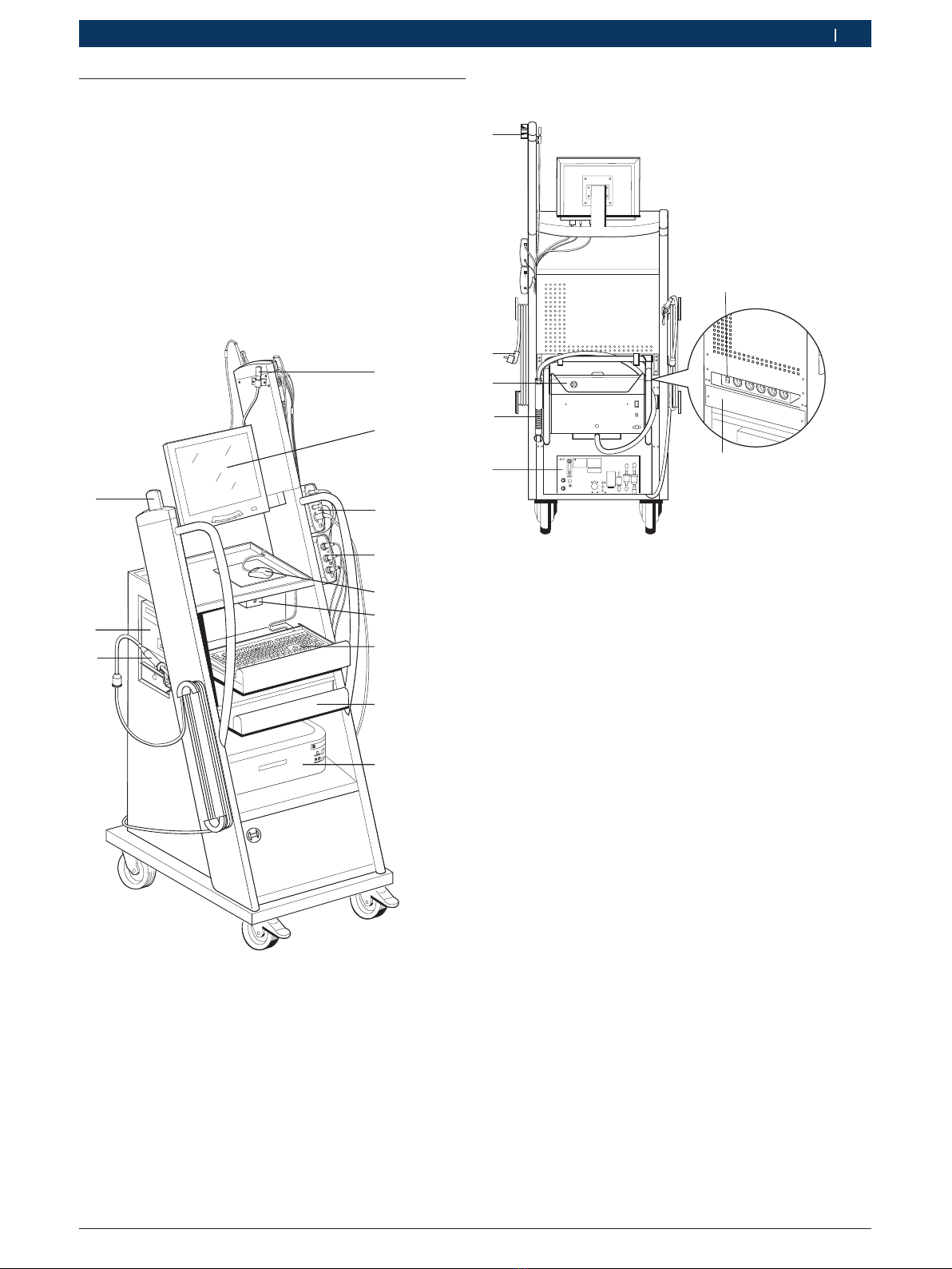
3. Produktbeschreibung
3.1 Bestimmungsgemäße Verwendung
Die Bosch-Emissions-Analyse, nachfolgend als BEA
bezeichnet, dient der anwenderfreundlichen Durchfüh-
rung von Abgasmessungen an Fahrzeugen. Prüflinge
sind das gesamte Fahrzeugspektrum von Otto- und Die-
selfahrzeugen, die am Straßenverkehr teilnehmen und
an denen Emissionsmessungen, einerseits auf Grund
gesetzgeberischer Maßnahmen und anderseits zur Feh-
lerlokalisierung und Fehlerbehebung, im Rahmen des
Werkstattbesuches durchgeführt werden müssen.
!Wenn BEA 950 und das mitgelieferte Zubehör anders
als vom Hersteller in der Betriebsanleitung vorge-
schrieben betrieben wird, kann der von BEA 950
und dem mitgelieferten Zubehör unterstützte Schutz
beeinträchtigt sein.
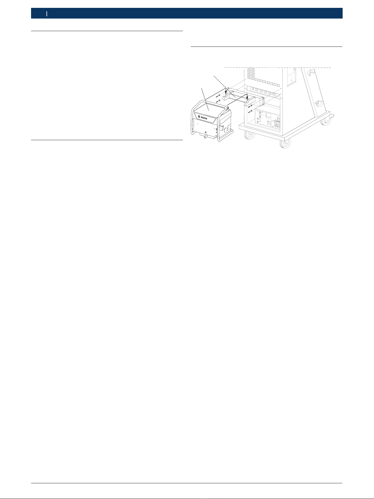
3.2 Lieferumfang
iDer Lieferumfang ist abhängig von der bestellten Pro-
duktvariante und dem bestellten Sonderzubehör und
kann von der nachfolgenden Auflistung abweichen.
Benennung Bestellnummer
Fahrwagen mit PC, Monitor, Fernbedienung
(mit Batterien), Maus mit Mausunterlage –
BEA 030 mit Netzteil –
BEA 055 1 687 023 550
BEA 070 1 687 023 638
Netzanschlussleitung für BEA 070 (4 m) 1 684 461 182
Batterieanschlussleitung B+/B– 1 684 463 822
Anschlussleitung für
Zigarettenanzünderbuchse 1 684 463 547
Primär-Adapterleitung 1 684 460 196
PDR 377 1 687 023 685
Grobfilter 1 687 432 005
Halterung für BEA 070 –
Schlauchleitung für BEA 070 und
Abgasentnahmesonde (Diesel) 1 680 703 047
1 680 790 044
Reinigungsbürste 1 687 929 006
Schlauchleitung für BEA 055 und
Abgasentnahmesonde (Benzin) 1 680 706 043
1 680 790 049
Bluetooth-USB-Adapter –
USB-Verbindungsleitung (1 m) 1 684 465 491
USB-Verbindungsleitung (5 m) 1 684 465 563
Softwarepaket mit SystemSoft BEA-PC –
Recovery-DVD-ROM 1 687 005 132
Mitgeltende Unterlagen 1 689 979 922
1 689 989 179
1 689 989 181
1 689 989 183
1 689 989 184
1 689 989 266
1 689 989 277
1 689 989 312
1 689 989 347
1 689 989 362
2. Benutzerhinweise
2.1 Wichtige Hinweise
Wichtige Hinweise zur Vereinbarung über Urheberrecht,
Haftung und Gewährleistung, über die Benutzergruppe
und über die Verpflichtung des Unternehmens finden
Sie in der separaten Anleitung "Wichtige Hinweise und
Sicherheitshinweise zu Bosch Test Equipment".
Diese sind vor Inbetriebnahme, Anschluss und Bedie-
nung von BEA 950 sorgfältig durchzulesen und zwin-
gend zu beachten.
2.2 Sicherheitshinweise
Alle Sicherheitshinweise finden Sie in der separaten
Anleitung "Wichtige Hinweise und Sicherheitshinweise
zu Bosch Test Equipment". Diese sind vor Inbetriebnah-
me, Anschluss und Bedienung von BEA 950 sorgfältig
durchzulesen und zwingend zu beachten.
2.4 EG-Konformitätserklärung
BEA 950 trägt die CE-Kennzeichnung in Übereinstim-
mung mit den einschlägigen EG-Richtlinien. Die EG-
Konformitätserklärung finden Sie auf
http://downloads.bosch-automotive.com als Adobe PDF-Doku-
ment.
2.3 Funkverbindungen
iDer Betreiber von Funkanlagen hat dafür zu sorgen,
dass die Richtlinien und Einschränkungen des jewei-
ligen Landes eingehalten werden.
Eine "Funkanlage" im Sinne der europäischen Richtlinie
RED 2014/53/EU (Radio Equipment Directive) ist ein
elektrisches oder elektronisches Erzeugnis (Komponen-
te), das zum Zweck der Funkkommunikation und/oder
der Funkortung bestimmungsgemäß Funkwellen aus-
strahlt und/oder empfängt.
Hinweise zu WLAN und Bluetooth finden Sie in der
separaten Anleitung "Wichtige Hinweise zu Funkverbin-
dungen und Connected Repair (CoRe)". Diese sind vor
Inbetriebnahme, Anschluss und Bedienung von BEA 950
sorgfältig durchzulesen und zwingend zu beachten.