Timeguard Weathersafe IS3N-20 Manual

Installation & Operating Instructions
IP65 Isolator Switches
Model: IS3N-20 – 3 Pole, 20A
Model: IS4N-20 – 4 Pole, 20A
Model: IS4N-40 – 4 Pole, 40A
Model: IS4N-63 – 4 Pole, 63A
Model: IS3N-32 – 3 Pole, 32A
Model: IS4N-32 – 4 Pole, 32A
Model: IS4N-100 – 4 Pole, 100A

IS4N-100
Manual Motor Controller EN60947-3
MOTOR 120V 240V 415V 220V 415V
3ph HP 10 25 50 lu = lth = AC21A 100A
1ph HP 5 15 30 AC-23A 3ph 22kW 37kW
100A 415V AC AC-3 1ph 18.5kW 30kW
IS4N-63
Manual Motor Controller EN60947-3
MOTOR 120V 240V 415V 220V 415V
3ph HP 5 10 20 lu = lth = AC21A 63A
1ph HP 2 5 10 AC-23A 3ph 11kW 22kW
63A 415V AC AC-3 1ph 11kW 22kW
IS4N-40
Manual Motor Controller EN60947-3
MOTOR 120V 240V 415V 220V 415V
3ph HP 3 7.5 15 lu = lth = AC21A 40A
1ph HP 1.5 3 7.5 AC-23A 3ph 7.5kW 15kW
40A 415V AC AC-3 1ph 7.5kW 11kW
IS3N-32 and IS4N-32
Manual Motor Controller EN60947-3
MOTOR 120V 240V 415V 220V
415V
3ph HP 1.5 3 5 lu = lth = AC21A 32A
1ph HP 0.5 1.5 3 AC-23A 3ph 7.5kW
32A 415V AC AC-3 1ph 5.5kW
IS3N-20 and IS4N-20
Manual Motor Controller EN60947-3
MOTOR 120V 240V 415V 220V
415V
3ph HP 1.5 3 5 lu = lth = AC21A 20A
1ph HP 0.5 1.5 3 AC-23A 3ph 5.5kW
20A 415V AC AC-3 1ph 4.0kW
2
1. Dimensions
2. Installation Instructions
4. Specifications
3. Cleaning
Please note that all instructions are to be left with the
customer after installation
The Weathersafe Isolator range is manufactured from tough, durable
thermoplastic, and is intended for use in an outdoor environment,
or one in which the protection provided by the Weathersafe Extreme
range is required. The protection level is IP65.
• These products should be installed by a competent person
(e.g. qualified electrician) in accordance with these instructions and
in compliance with the appropriate clauses of the current edition of
the IEE wiring and building regulations.
• The Weathersafe Isolator range is designed to be mounted on a
vertical flat surface.
• The rear box shall be mounted on the wall using fixings and wall
plugs if necessary. The fixing dimensions are marked on the back
of the rear box.
• The front moulding can only be removed when the switch is on
the OFF position.
• The terminals should be tightened to a torque of 1.8Nm.
Do not exceed the maximum cables sizes:
• 20A 2.5mm2
• 32A 6mm2
• 40A and 63A 16mm2
• 100A 25mm2
• A cable gland of IP65 or higher should be used in order to maintain
the IP rating.
• The relevant cable entry knockout should be carefully removed by
scoring the groove around the required knockout with a sharp knife
and then tapping it out with a small hammer onto a screwdriver in
the groove.
• When re-assembling the enclosure ensure that the gasket is fully in
place in order to retain the IP65 rating.
• Tighten the screws supplied to refix the front cover in place. Do not
overtighten. Use of an electric screwdriver is not recommended.
• Advice should be sought before installing this product in an
environment where it is likely to be subjected to chemicals,
oils or solvents.
Care should be taken when cleaning this product.
• Inside the lid should only be wiped with a clean dry cloth.
• The outside can be cleaned with mild detergent.
• Solvent based cleaners should not be used.
A
C
E
B
ØD1
H
F
IS4N-40
Manual Motor Controller IEC947-3, EN63947-3, VDE0660-107
MOTOR 120V 240V 480V 600V 220V 380V 690V
440V
3ph HP 3 7.5 15 15 Iu=Ith=AC21A 40A
1ph HP 1.5 3 7.5 7.5 AC-23A 3ph 7.5kW 15kW 18.5kW
40A 600VAC AC-3 1ph 7.5kW 11kW 11kW
IS4N-63
Manual Motor Controller IEC947-3, EN63947-3, VDE0660-107
MOTOR 120V 240V 480V 600V 220V 380V 690V
440V
3ph HP 5 10 20 20 Iu=Ith=AC21A 63A
1ph HP 2 5 10 10 AC-23A 3ph 11kW 22kW 22kW
63A 600VAC AC-3 1ph 11kW 22kW 15kW
IS4N-100
Manual Motor Controller IEC947-3, EN63947-3, VDE0660-107
MOTOR 120V 240V 480V 600V 220V 380V 690V
440V
3ph HP 10 25 50 50 Iu=Ith=AC21A 100A
1ph HP 5 15 30 30 AC-23A 3ph 22kW 37kW 30kW
100A 600VAC AC-3A 1ph 18.5kW 30kW 22kW
IS3N-20 and IS4N-20
Manual Motor Controller IEC947, EN60947-3, VDE0660
MOTOR 120V 240V 480V 600V 220V 380V
440V 690V
3ph HP 1.5 3 5 5 Iu=Ith=AC21A 20A
1ph HP 0.5 1.5 3 3 AC-23A 3ph 5.5kW 7.5kW
20A 600VAC AC-3 1ph 4.0kW 5.5kW
IS3N-32 and IS4N-32
Manual Motor Controller IEC947, EN60947-3, VDE0660
MOTOR 120V 240V 480V 600V 220V 380V
440V 690V
3ph HP 1.5 3 5 5 Iu=Ith=AC21A 32A
1ph HP 0.5 1.5 3 3 AC-23A 3ph 7.5kW 11kW
32A 600VAC AC-3 1ph 5.5kW 7.5kW
A B C D1 E F H
For assistance with the product please contact:-
Helpline
020-8450-0515
or emailhelpline@timeguard.com
For a product brochure please contact:
Timeguard Ltd.
020-8452-1112
or email csc@timeguard.com
Timeguard Limited
Victory Park, 400 Edgware Road, London NW2 6ND
A Group Company
67.058.471 (iss. 1)
3 Year Guarantee
In the unlikely event of the product becoming faulty due
to defective material or manufacture within 3 years of the
date of purchase, please return it to your supplier in the first year with
proof of purchase and it will be replaced free of charge.
For the second and third years or any difficulty in the first year telephone
the helpline on 020 8450 0515
50Hz
50Hz
50Hz
50Hz
50Hz
Zerofour – December 2016
67-058-525 (Issue 2)
Timeguard Limited.
Victory Park, 400 Edgware Road, London NW2 6ND
Sales Office: 020 8452 1112
or email csc@timeguard.com
For a product brochure please contact:
For assistance with the product please contact:
HELPLINE 020 8450 0515
3 Year Guarantee
In the unlikely event of this product becoming faulty due to defective material
or manufacture, within 3 years of the date of purchase, please return it to
your supplier in the first year with proof of purchase and it will be replaced
free of charge. For years 2 to 3 or any difficulty in the first year, telephone
our helpline on 020 8450 0515.
Note: a proof of purchase is required in all cases. For all eligible replacements
(where agreed by Timeguard) the customer is responsible for all shipping/
postage charges outside of the UK. All shipping costs are to be paid in
advance before a replacement is sent.
or email helpline@timeguard.com
www.timeguard.com
A B C D1 E F H
IS3N-20 IS4N-20 100 82 90 2x M20 60 60 65
IS3N-32 IS4N-32 141 100 126 2x M20/25 75 100 68
IS4N-40 IS4N-63 175 121 161 2x M20/25 96 135 91
IS4N-100 240 160 IS4 2x M25/32
50Hz
50Hz
50Hz
50Hz
50Hz
142 193 95
1x M20
This manual suits for next models
6
Other Timeguard Switch manuals
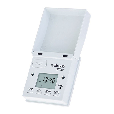
Timeguard
Timeguard ZV700B Manual
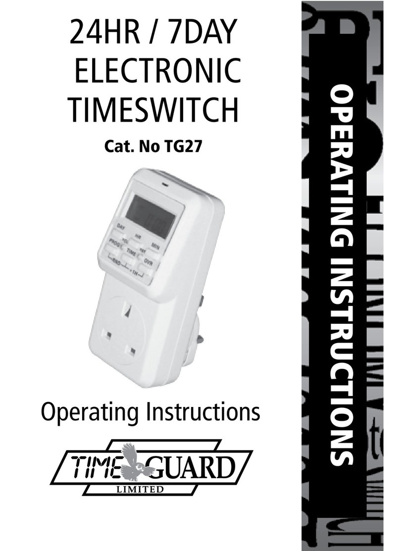
Timeguard
Timeguard TG27 User manual
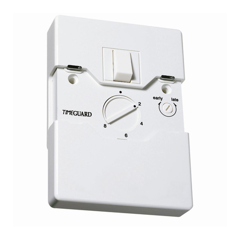
Timeguard
Timeguard ZV210 User manual
Timeguard
Timeguard Weathersafe Vision TGVL01 Manual
Timeguard
Timeguard NTTHDA User manual

Timeguard
Timeguard ZV210 User manual
Timeguard
Timeguard TuyaSmart FSTWIFITUTGV Manual
Timeguard
Timeguard NTM02 Manual
Timeguard
Timeguard DS1 User manual

Timeguard
Timeguard ZV210 User manual
