Osram e:cue Bridge8 Specification sheet

Our Brand
www.osram.com/ecue
Light is OSRAM
AM356960031
e:cue Bridge8
Information for Use / Bedienungsanleitung

02
AM356960031
e:cue Bridge8 Information for Use (original issue)
e:cue Bridge8 Bedienungsanleitung (Originalversion)
Edition / Ausgabe:
23.07.20 [EN_DE_ecue_Bridge8_Setup_v1p3]
Published by / Herausgegeben von:
OSRAM GmbH
Karl-Schurz-Strasse 38
33100 Paderborn, Germany
©2020 OSRAM GmbH, BU Digital
All rights reserved / Alle Rechte vorbehalten
Art-Net™ Designed by and Copyright Artistic Licence Holdings Ltd

03
Read the Setup Manual and
the Safety instructions carefully.
Subject to modication without
prior notice. Typographical and
other errors do not justify any
claim for damages. All
dimensions should be veried
using an actual part.
Modication of the product is
prohibited.
This manual is designed for
electricians, system
administrators, and product
users.
All product names mentioned
in this manual are trademarks
of their respective owners.
Except for internal use,
relinquishment of the
instructions to a third party,
duplication in any type or form
- also extracts - as well as
exploitation and / or
communication of the contents
is not permitted.
Lesen Sie die
Installationsanleitung und das
Heft "Sicherheitshinweise"
sorgfältig durch. Alle Änderungen
vorbehalten. Rechtschreibfehler
oder andere Fehler rechtfertigen
keinen Anspruch bei Schäden.
Alle Maße sollten an einem realen
Gerät überprüft werden.
Modikation des Produktes ist
verboten.
Diese Anleitung richtet sich an
Installateure, IT-Administratoren
und Benutzer des Produktes.
Alle in dieser Anleitung
genannten Bezeichnungen von
Erzeugnissen sind Marken der
jeweiligen Hersteller.
Außer für interne Verwendung ist
die Überlassung dieser Anleitung
an Dritte, die gesamte oder
auszugsweise Veröffentlichung,
Verwertung oder Mitteilung in
jeglicher Art und Form nicht
gestattet.
04
Table of Contents / Inhalt
English 07
1 Security instructions 08
1.1 Symbols 08
1.2 General security instructions 08
2 General device description 09
2.1 Delivery content 10
2.2 Connectors and Interfaces 11
2.3 User interface: LEDs 12
2.4 Identify button: Identication & Reset 13
3 General remarks 14
3.1 Transport 14
3.2 Unpacking 14
3.3 Warranty regulations 14
3.4 Maintenance and Repair 14
3.5 Disposal 15
3.6 Support 15
4 Installation 15
4.1 Installation conditions 16
4.2 Mounting process 16
4.3 Ethernet connection 16
4.4 DMX connection 17
4.5 Power supply 17
4.6 Protective Earth 18
5 Network configuration 19
5.1 Default network properties 19
5.2 Network conguration with the web interface 19
6 Output configuration 21
6.1 Ports conguration 22

05
Table of Contents / Inhalt
6.2 Data mapping (Sources conguration) 22
6.3 Source switch 24
7 Test mode 25
7.1 Test mode via Test button 26
7.2 Test mode via web interface 26
8 Firmware Update 28
9 Dismounting 29
10 Product specifications 30
11 Certifications 31
Deutsch 32
12 Sicherheitshinweise 33
12.1 Symbole 33
12.2 Sicherheitshinweise 33
13 Gerätebeschreibung 34
13.1 Lieferumfang 35
13.2 Anschlüsse und Schnittstellen 36
13.3 Benutzeroberäche: LEDs 37
13.4 Identify-Taster: Identizierung & Reset 38
14 Allgemeine Hinweise 39
14.1 Transport 39
14.2 Entpacken 39
14.3 Garantiebestimmungen 39
14.4 Wartung und Reparatur 40
14.5 Entsorgung 40
14.6 Technischer Support 40
15 Installation 41
15.1 Installationsbedingungen 41
15.2 Montage 41
15.3 Ethernet-Verbindung 42
15.4 DMX-Verbindung 42

06
Table of Contents / Inhalt
15.5 Spannungsversorgung 43
15.6 Erdung 43
16 Netzwerk-Konfiguration 44
16.1 Standardeinstellungen vom Netzwerk 44
16.2 Netzwerkeinstellung über die Webschnittstelle 45
17 Ausgabe-Konfiguration 47
17.1 Ausgangs-Konguration 48
17.2 Datenzuordnung (Quellen-Konguration) 49
17.3 Quellenwechsel 50
18 Testmodus 52
18.1 Testmodus über Test-Taster 52
18.2 Testmodus über Webschnittstelle 53
19 Firmware-Update 54
20 Demontage 56
21 Produktdaten 57
22 Zertifizierung 58
Dimensions / Abmessungen 59

07
English

08
Security instructions
1 Security instructions
Please read and follow the safety instructions, provided in a separate
manual, carefully. Make sure that the environmental, mounting, and
installation prerequisites are met. This manual should be kept at a safe
place and in reach of the device.
1.1 Symbols
!
The exclamation mark warns about possible damage of the
device itself or connected devices.
i
The information symbol gives general hints and informs
about handling and procedures for use of the device.
1.2 General security instructions
!
Connect cables and data only when the device is powered
down.
!
Ground the Ethernet and DMX connection cables for outdoor
installations (optional for indoor only). Connect the
e:cue Bridge8 to Protective Earth when at least one
connected cable runs outdoor.
!
The device must be supplied by a separate certied SELV
Class 2 power supply.
i
If security instructions are missing, please contact the
OSRAM support service to receive a new copy.

09
General device description
2 General device description
Lighting applications are heterogenous by nature. e:cue interfaces serve to
integrate many networks, protocols and third party products into e:cue
solutions. They also aid in applying special control functions for xtures,
they integrate analog or mechanical signaling into the digital world and offer
bridging functions. e:cue interfaces are the links to bring together the many
techniques and technologies of lighting control.
e:cue Nodes are a system of interfaces and provide various connection
types like DMX/RDM, DALI, digital inputs and outputs etc
The e:cue Bridge8 is an Art-Net / sACN to DMX interface. It comes with 8 x
DMX universes over screw terminal plugs. Switch between two input
sources on the y. The e:cue Bridge8 makes it possible to run up to 4096
DMX channels (= 1360 RGB pixels, 170 Pxl/Univ.) over Ethernet. The
e:cue Bridge8 supports up to 32 sACN / Art-Net universes.
With an extended operating temperature of -40 ... 70°C (max 1 hour/day;
continuous operation at max. 60 °C) the e:cue Bridge8 is suited for projects
in tough outdoor environments. In addition to embedded temperature and
humidity sensors, a backup on data loss and test modes add to the
features of the Node.
The Node is powered by an external power supply or via Power-over-
Ethernet. It is easily mounted on standard 35 mm DIN rails, or with a key
hole in the housing base on walls or on any stable vertical surface.
i
e:cue Noes are not hot-pluggable.

10
General device description
2.1 Delivery content
Delivery content of the e:cue Bridge8 -
Product number AM356960031
1. e:cue Bridge8
2. Safety instructions
3. Installation guide.

11
General device description
2.2 Connectors and Interfaces
View from top:
1DMX output 1 ... 8
(GND, DMX-, DMX+ left to right)
2DMX status LEDs
3Test / Error LED
4Ethernet LED (LAN activity)
5Status LED (Device status)
6Identify button
7Test button
8Protective Earth
9Power supply (Vcc+, Vcc- left to right)
10 Ethernet
11 DIN rail handle
1
3
4
5
6 7
8 9 10
11
2

12
General device description
2.3 User interface: LEDs
The e:cue Bridge8 has 11 LEDs on the front panel. The 11 LEDs show the
basic states of the e:cue Bridge8.
LEDs
Status On: If constantly on, the device is online. Server
application is in operation.
Blinking: If blinking in one second intervals, the
device is ofine. If blinking more rapidly, the device is
in bootloader mode.
Ethernet Off: no link available.
On: link established.
Blinking: Ethernet trafc.
Test / Error Off: no error detected.
Short-short-long sequence: Test mode active.
On: If constantly lights in red, an error occurred. This
can be an internal error or malfunction of the device,
or an external error, e.g. a shortcut of interface
connections or alien power supply. Switch the device
off and on. If the error persists, check the wiring or
contact OSRAM Service.
DMX 1 ... 8 Orange: DMX data.
Orange + White: port error.

13
General device description
2.4 Identify button: Identification & Reset
The Identify button has two functions: to reset the Node (A), and to exit the
error state (B).
(A) The Identify button can be used to reset the device to factory state or to
stay in bootloader mode. With a reset you restore the password and device
settings by using the Identify button. Please note that the device name is
not reset:
• Keep the Identify button pressed while powering up, Status and
Test / Error LEDs light up at rst. Bootloader mode is signaled by a fast
blinking Status LED. Release the button now. The device stays in
bootloader mode to download a new rmware.
To exit the bootloader mode, short press the Identify button again.
• Press the Identify button during operation until Status and
Test / Error LEDs blink alternating, then blink together. Releasing the
button now resets the device to its factory settings. The password and
network settings are reset to their default values. Please note that the
device name cannot be reset.
• Keeping the button pressed further on, the device proceeds to
normal operation. No changes apply.
(B) Short press the Identify button if an error occurs and you want to exit
the error mode. The device will switch back to normal activity if the cause of
error is eliminated. The Node might reboot.

14
General remarks
3 General remarks
3.1 Transport
Only transport the device in its original packaging. This protects the device
from damage.
3.2 Unpacking
Only unpack the device at its installation location. To protect the device
against condensation water, unpack it and wait until all moisture remaining
in the device has evaporated. Condensation can occur when the device is
moved from a cold to a warm location. Keep the packaging for use in case
of further transport. Inspect all parts for completeness regarding chapter
“2.1 Delivery content” (page 10). If there is apparent damage to the
device or parts are missing from the delivery scope, please contact the
OSRAM support service.
3.3 Warranty regulations
Depending on the product, guaranty regulations are of different duration.
The warranty time is usually noted in the quote and in the order
conrmation. See “Services” “OSRAM Guarantees” at www.osram.com
for details. Legal warranty regulations apply in any case.
3.4 Maintenance and Repair
This device requires no maintenance.
!
Before dismounting, appropriate measures must be taken to
protect the respective components against damage caused
by electrostatic discharge (ESD protection).
!
Do not try to repair the device. Return it to your OSRAM
distributor for replacement or repair.

15
Installation
To update the rmware see „8 Firmware Update“ on page 28.
3.5 Disposal
The proper disposal of packing materials and of the device is the
responsibility of the respective user and for his account; in all other matters,
the retrieval obligation for packing materials and the device is subject to the
statutory regulations.
3.6 Support
In case of technical problems or questions regarding installation and repair
please contact:
OSRAM GmbH
Customer Service
Karl-Schurz-Str. 38
33100 Paderborn, Deutschland
+49 (5251) 54648-0
4 Installation
The installation of the e:cue Bridge8 consists of mounting the device,
connections to power supply, to Ethernet, and to the DMX devices.
The sequence of cabling is not dened. Supply the device with power after
all cabling is completed; it starts booting.
Batteries and technical appliances must not be disposed of
with domestic waste, but should be handed in at the
appropriate collection and disposal points.
!
Connect cables and data only when the device is powered
down.

16
Installation
4.1 Installation conditions
Installation position Terminals on top and bottom
Horizontal spacing On both sides 18 mm
Minimum vertical rail grid spacing 115 mm (90 + 25 mm)
(excluding conduit)
Recommended vertical rail grid spacing 160 mm (with 40 mm conduit)
4.2 Mounting process
The e:cue Bridge8 is designed to mount onto a 35mm DIN rail (EN 60715)
in a horizontal position.
1. Clip the device to the rail from
top.
2. Apply gentle pressure to the
top front to snap it in place. The
device has been mounted
successfully.
You can also mount the device on any at surface. Use a 3 to 3.5mm screw
for the hanger hole.
For mechanical stability, mounting on a rail is recommended.
4.3 Ethernet connection
The pin-assignment of the Ethernet port corresponds to RJ45 standards.
You can use every common Ethernet component, like cable, splitters, and
switches. Connect the e:cue Bridge8 at the designated Ethernet interface
with a patch cable (RJ45, CAT5).
1
2
!
Ground the Ethernet cable for outdoor installations (optional
for indoor only).

17
Installation
4.4 DMX connection
The e:cue Bridge8 can control eight DMX universes with its eight DMX
ports. Connect DMX devices to the Node using 3-pin terminal plugs at the
DMX interface of the Node.
The appropriate pin assignment is dened as follows:
From left to right: GND, DMX-, DMX+
It is recommended to use twisted pair cabling.
Use shielded cables for outdoor installations.
4.5 Power supply
The e:cue Bridge8 can be powered by an external power supply or via
Power-over-Ethernet.
PoE:
For PoE, simply connect an Ethernet connection from a power sourcing
device.
External power supply:
Connect the e:cue Bridge8 to a certied NEC Class 2 24 V DC power
supply unit. Present power supply equates to the status “On” or running of
the Node.
i
Never connect more than one e:cue Bridge8 in factory state
to a network. The identical IP addresses will conict and
disturb proper communication.
!
Ground the DMX connection cable for outdoor installations
(optional for indoor only). Ground each cable seperately.

18
Installation
To connect the device to a power supply unit, use the provided 2-pole
terminal and lay the wires as stated on the front label. The voltage
assignment is left V+ and right V-.
Turn the power on when all cables are connected to the e:cue Bridge8. The
device starts booting. During the booting process all DMX LEDs turn on
consecutively. The device has nished booting and is in operation when the
LED Status is ashing.
4.6 Protective Earth
Grounding of the e:cue Bridge8
Use Protective Earth where
applicable.
Ground the DMX connection
cable and the Ethernet cable.
Ground each cable separately.
i
The e:cue Bridge8 is not suited for powering over a DC
power supply network. Use a separate certied SELV Class
2 power supply unit in the control cabinet for supplying 24 V
DC to the e:cue Bridge8.
!
Connect the e:cue Bridge8’s Portective Earth to earth when
at least one connected cable runs outdoors.

19
Network conguration
5 Network conguration
The network properties of the device are precongured. The successful
installation of the power supply is required for changing the network
conguration. You can either adjust the network settings using the web
interface of the device.
5.1 Default network properties
The e:cue Bridge8 has as factory setting the default IP address
192.168.123.1.
Subnet mask: 255.255.255.0.
DHCP is disabled by default.
Login credentials for the web interface of the e:cue Bridge8:
The default password is: ecue
To change the network conguration use the web interface of the device.
5.2 Network configuration with the web interface
1. Open a common web browser on a connected PC. Enter the
e:cue Bridge8’s IP address into the address bar:
e.g. http://192.168.123.1.
The web interface of the device is displayed:

20
Network conguration
2. On the left side, select “Settings” and enter the default password
ecue:
3. Click “Apply”. The Settings page is displayed:
4. Dene the network settings at “Device Basics” to your needs. You
can also change the password for entry to the web interfaces of the
device here. Entering an empty value disables the password protection.
5. Click “Submit” to apply the settings.
The network conguration of the device is completed.
i
The employment of a discrete network is recommended.
i
Note down all employed and, if applicable, reserved IP
addresses. Keep the information for future network
congurations.
This manual suits for next models
2
Table of contents
Languages:
Other Osram Recording Equipment manuals

Osram
Osram e:cue SYMPL dmx User guide

Osram
Osram e:cue SYMPL Switch User guide

Osram
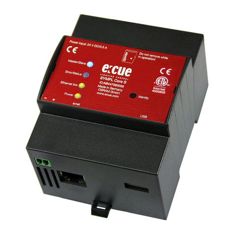
Osram e:cue SYMPL Core S User guide

Osram
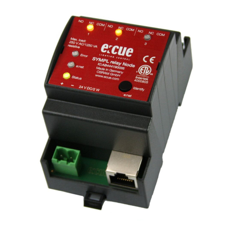
Osram e:cue SYMPL relay Node User guide

Osram
Osram e:cue SYMPL dali Node User guide

Osram
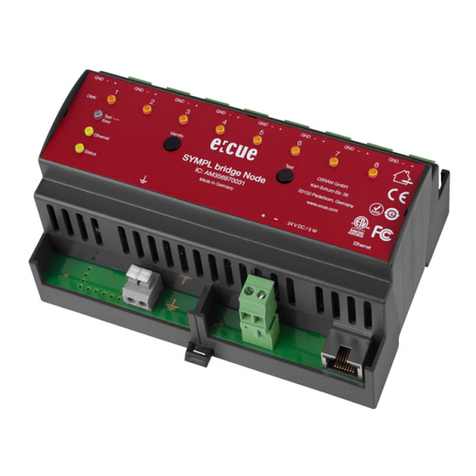
Osram e:cue SYMPL bridge Node Specification sheet

Osram
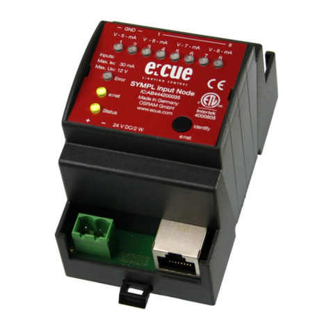
Osram e:cue SYMPL input Node User guide

Osram
Osram e:cue SYMPL e:bus Node User guide