Timitoo TEK-608A User manual

Operating Instructions
TEK –608A
Broadband Modem with Ultrasonic Sensor
V1/072017

Page 2
Contents
1 Introduction............................................................................................. 3
2 Contents of Package................................................................................ 3
3 Modem User Interface ............................................................................ 4
3 Installing the Broadband Modem............................................................ 5
4 Preparing the Tank .................................................................................. 6
4 Define Tank Height.................................................................................. 6
5 Activating the Sensor.......................................................................... 7
6 Fitting the Sensor .................................................................................... 7
7 Interacting with the Modem via a Browser............................................. 8
9 Online Setup.......................................................................................... 12
10 Troubleshooting ..................................................................................12
1: No RF reading received for 6 hours..................................................12
2: MAC Address/IP link failed............................................................... 12
3: No valid IP......................................................................................... 12
4: Unable to connect to Server ............................................................13
5: Server did not respond correctly...................................................... 13
6: File download failed .........................................................................13
7: RF self-test failed.............................................................................. 13
Low Battery (indicated in online application) ......................................13
11 Specifications....................................................................................... 14
11 Warning ............................................................................................... 14
Warranty Registration..............................................................................15
Support.....................................................................................................15

Page 3
1 Introduction
The TEK-608A is a Broadband modem, allowing to connect up to 4 Ultrasonic
Tank Monitoring Sensors and transmit the data to the Timitoo Tank Monitoring
Website.
In this online application the level of the tanks can be read in a diagram, showing
the consumption over time, as well as the current level and remaining days of
supply.
The tanks can also be set up as tanks that are filling up, i.e. Waste liquid tanks.
Individual alarms can be set to notify of tanks that are becoming empty, or in
case of waste tanks, becoming full.
2 Contents of Package
Adapter Kit
Power Supply
Transmitter
Sensor
Broadband Modem
RJ45 Network
Cable
Weather Seal

Page 4
3 Modem User Interface
The TEK-608A has a simple user interface of 3 LEDs (Yellow, Green and
Red) and a momentary push button.
The table below describes the functions and a brief summary of the LED lights of
the TEK-608A broadband modem.
LED Color
Primary Function
Secondary Function
Amber
Power LED. On solid when Power is on
Green
RF Data LED. Flashes when RF data
packet is received.
During firmware download
process it will flash rapidly.
Red
Error LED
Display Erro Flash Codes:
1: No RF reading received for 6 hours
2: MAC Address/IP link failed
3: No valid IP
4: Unable to connect to Server
5: Server did not respond correctly
During boot loading process
indicates flash memory
programming.
Amber
Green
Red
Button
Power
Ethernet
Magnet
location
dot
Black
dot

Page 5
6: File download failed
7: RF self-test failed
Amber +
Green
LED’s On solid indicate unit is
attempting to connect to the server.
Amber + Green double flash
to indicate a successful
connection to the server.
Amber +
Green +
Red
All three LED’s on solid indicate the
unit is powering up. If this does not
clear, please contact support.
Indicates a sensor is being
activated (and matched if
sensor matching is enabled).
3 Installing the Broadband Modem
Please unpack the broadband modem from the packaging and screw the
antenna onto the unit, if it is not already pre-installed.
The Ethernet port (right hand of the picture) must be connected to your internet
high speed connection router. No additional bridges or routers are required. The
modem should have “line of sight”to the tank sensor transmitter and should not
exceed 250ft of distance.
Please note that the distance will decrease with obstacles such as walls or glass
between the modem and the transmitter.
The Ethernet-cable delivered is approximately 1m/3ft long, but a longer cable of
up to 100m/328ft can be used.
The left plug in the picture above is for the power supply, which is also delivered
in the packaging.
Upon correct installation and activation the green LED light in the corner of the
Ethernet plug will blink. If this light remains off, the connection to the Router is
faulty.

Page 6
4 Preparing the Tank
a. To avoid errors, the Tank Gauge Transmitter must sit in a vertical position
on top of the tank and have a direct perpendicular line of sight to the
liquid level in the tank, through the bottom ultrasonic cone, without any
interference from i.e. window configurations or tank braces.
b. Install the supplied metal adapter into the pre-drilled 2” NPT opening on
the top of the tank. Apply pipe sealant on the adapter thread and tighten
appropriately. For basement tanks, temporarily place a rag/cover over
the adapter to minimize fuel odors until transmitter is synchronized.
Tanks with 1½ and 1¼ ” NPT openings or European style double-wall
tanks require adapters (see parts sold separately). Do not use an
extension pipe when mounting the adapter; this can cause inaccurate
measurement and malfunction.
c. Installation Help:
Avoid tanks with braces, as it can reflect the ultrasound and cause
wrong readings.
4 Define Tank Height
Accurately measure the height of your tank from the liquid outlet at the bottom
of your tank to the bottom of the ultrasonic Sensor Transmitter. The sensor
measures the distance from the sensor to the level of the surface of the liquid
within the tank. Any setting for the shape of the tank, its content and the volume
of the tank are entered into the online setup of the Tank Monitoring website:
https://online.tankmonitoring.net

Page 7
5Activating the Sensor
Remove the sensor from packaging
Recycle the power on the modem and it will enter the “Learn mode”for
two minutes. Hold the black dots of the modem and the black dot on
the sensor together.
All 3 LED’s will flash while the transmitter is matching to the receiver.
Once the matching process is complete the green LED will light up for 5
seconds and will no longer be flashing.
The unit will not immediately try to connect to the server and then
revert to the listen mode.
Also consult the online video:
6 Fitting the Sensor
For tanks with pre-drilled 32mm holes:
Remove cap from pre-drilled hole and insert transmitter, ensuring the
weather seal is securely in place and that the sensor sits vertically.
Tighten onto the tank with the supplied 2 stainless steel self-tapping
screws provided. Do not use longer screws or over tighten.
For tanks with a 2”, 1½” or 1¼” BSP/NPT gauge aperture
(60mm/48mm/42mm):

Page 8
Unscrew any caps from hole; fit adapter provided by screwing into
gauge socket.
Fit Sensor to adapter on the tank; ensure weather seal is in place.
Tighten on the tank using the screws supplied. Do not over tighten.
NOTE: Mounting Adapter supplied must only be used.
7 Interacting with the Modem via a Browser
Once the TEK-608A Broadband modem has been connected to the power supply
and to the networks router, the System Dashboard page can be viewed in a
web-browser.
In order to connect to the modem use the following URL:
HTTP://TEK608-XXXX
The XXXX must be replaced with the last 4 digits of the
modems serial number.
The sample to the right would need HTTP://TEK608-1897 as hostname to be
typed into the browser.
Please note that the hostname address can only be used with a Windows-based
PC or a MAC PC. Android or Apple Tablets/Smartphones do not have a native
way of dynamically discovering the hostname. In these cases the IP-address
must be discovered from the router.
System Dashboard

Page 9
The dashboard shows the status of the connection to the internet server, as well
as which sensors that are connected. Each sensor that was matched in the
previous process shows up named “Sensor 1”to “Sensor 4”automatically.
Setup Wizard
On the Setup Wizard Page, the name of the sensor transmitter can be renamed
and a new more descriptive name can be provided. The name is stored once the
“Next”button is at the bottom of the page is selected.
Setup Wizard Stage 2

Page 10
If the transmitter sensor serial number is already known and is already active,
the number may be typed in using the “Type in sensor serial”option.
It is however more typical to use the “Activate Sensor”option.
When the “Activate Sensor”option is selected and the “Next”button is clicked,
the Broadband modem is set to the “Learn Mode”and the screen below is
shown.
A magnet needs to be held to the Transmitter Sensor (at the black dot), or the
sensor is held to the black dot of the Broadband Modem.
Follow the instructions on the screen and hold the sensor next to the broadband
modem.
If the process is not started within 2 minutes, the activation persiod will
expire and the process must be restarted.

Page 11
Once successfully paired the page will show a registration form for the details of
the tank. The name of the sensor and the serial number will be pre-filled.
The transmitter sensor is now matched with the Broadband modem. The screen
will not be showing that data is being received from the newly matched sensor:
Once the transmitters are matched the data is received and forwarded on to the
online monitoring. Further setup is done at the online monitoring website.

Page 12
9 Online Setup
Once the system is up and running the tanks must be registered with the online
monitoring service. Please contact your seller about the different options on
how to activate the system for your use.
10 Troubleshooting
Problems typically only arise with the modem and the connectivity of the
sensors, or the connectivity to the server.
The red LED indicator on the Broadband modem provides the error code, by the
flashing sequence. By observing the red LED light, please note that there is a
longer break. From this point forward the amount of flashes should be counted
until a longer break is observed again. The number counted, represents the
error code of the issue described below:
1: No RF reading received for 6 hours
The Broadband modem does not receive any signal from the sensor transmitter.
This is usually when there is no direct line of sight, an unusual obstacle, or the
sensor transmitter was not properly matched.
Please refer to the matching sequence above in order to match the sensor again
and observe the Dashboard to verify the Sensor Transmitter sending data.
The sensor transmitter might also have reached the end of its battery life. Please
refer to the section below on how to exchange the battery in the sensor
transmitter.
2: MAC Address/IP link failed
The system could not receive an IP Address, or there is a conflict with the MAC
Address of the Broadband modem. Check with your Router settings and verify
the DHCP settings and DHCP Client on the network.
3: No valid IP
The broadband modem did not receive a valid IP Address through the DHCP
service, or the hardcoded IP Address is invalid. Please check with your network
router what the network address should be, or if the device is blocked.

Page 13
4: Unable to connect to Server
The system cannot connect to the server. The Broadband modem might be
blocked from external Internet access or the Router is down and cannot receive
any outside addresses.
The routers DHCP service might not be up to date. Try to restart the router,
check internet access via a browser and restart the broadband modem.
5: Server did not respond correctly
This message should not occur in normal operation. There might be however a
network issue preventing the remote servers reply to make it back to the
Broadband modem. Please contact customer service in this case.
6: File download failed
This error message can only occur when the system is remotely updated. This
requires maintenance access which is not done by the end-user.
7: RF self-test failed
When this error occurs customer service needs to check the unit, as this
indicates a hardware issue.
Low Battery (indicated in online application)
1. Remove transmitter from the tank and take it into a clean, dry environment.

Page 14
2. The battery can be accessed by removing 4 self-tapping screws from the base
of the unit.
3. Remove the old battery noting the
orientation (+ mark facing upwards) and
replace with a new battery (3V-CR2450)
4. Re-assemble, ensuring the O-Ring is
undamaged and secured in position.
5. Place the transmitter on the tank.
No need to re-match the sensors.
11 Specifications
Tank depth measurement:
Depth: 4ins./0.1m –10 ft.
(Use on tanks vented to the atmosphere)
Battery / battery life:
3-volt CR2450 lithium cell / up to 10 years.
Dimensions (modem):
Indoor use only
120 x 25 x 72 mm
4.7 x 1 x 2.8 inch
Max and min operating
temp. (transmitter):
Operating temperature range: +14°F to +140°F
Operating humidity: 0-100%
Sealed airtight unit made from PP3317 UV
stabilized
Hole size for tank fitting:
2 ins. Use adapters for tanks with pre-drilled 2”,
1½“or 1¼” BSP/NPT gauge aperture.
11 Warning
It is the user’s responsibility to avoid exposing the product to aggressive
substances e.g. liquids or gases that may attack metals, or solvents that may
affect polymeric materials.
The broadband modem is for indoor use only (the sensor is OK for
outdoor use).
The broadband modem is a sealed unit; do not attempt to open it.

Page 15
Periodically check that the unit is intact and securely fastened to the
tank.
Do not attempt to repair the product.
Clean only with a damp cloth.
Do not replace batteries in a potentially explosive atmosphere.
Do not discard batteries in a pressurized container.
Warranty Registration
Please register your product for warranty at:
https://www.tankmonitoring.net/warranty-registration.html
Support
Timitoo Tank Monitoring Solutions
4620 St. Charles Ct.
Flower Mound, TX 75022
http://www.tankmonitoring.net
support@tankmonitoring.net
(817) 778 4050
Table of contents
Popular Modem manuals by other brands
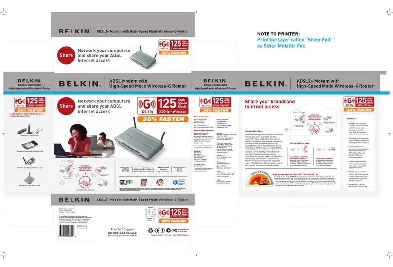
Belkin
Belkin F5D7633uk4A Brochure & specs
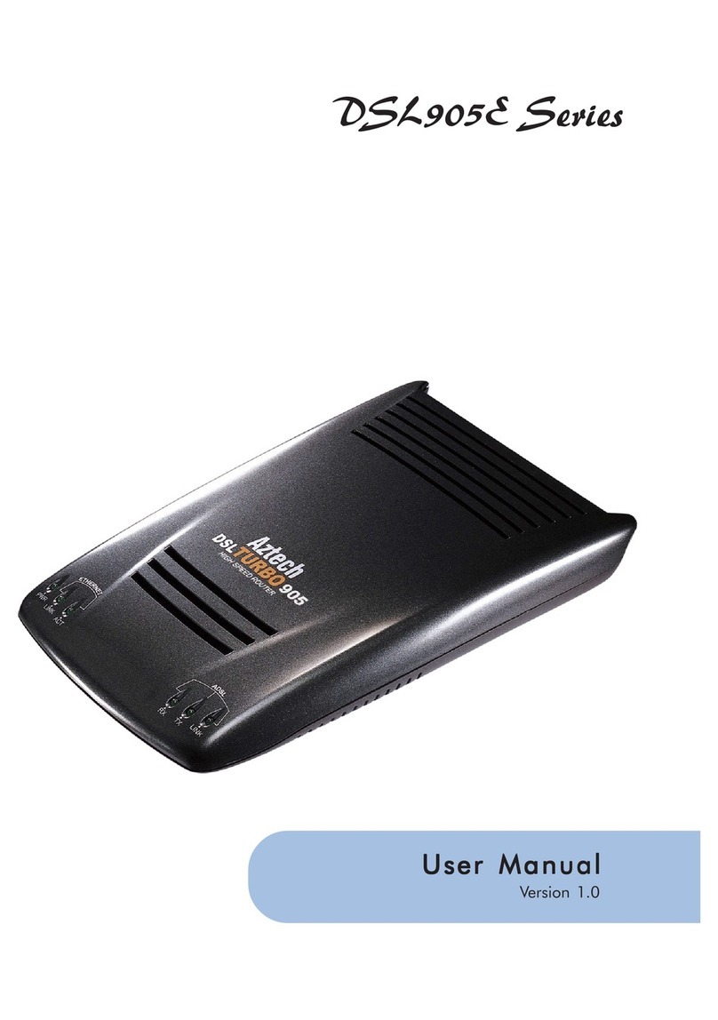
Aztech
Aztech DSL905E Series user manual

Cradlepoint
Cradlepoint AER1600 Series quick start guide
US Robotics
US Robotics SportsterVoice user guide
US Robotics
US Robotics 56K PCI FAXMODEM - QUICK REV 1 Quick installation guide
Patton electronics
Patton electronics 1070RC user manual
