Tippkemper CNS-SV 25 T User manual

Capacitance Level Sensor
CNS-SV 25 T
Level control for:
•waxes
•granulates
•paints
•hot-melt adhesives
•chemicals
Type
Technical data:
CNS-SV 25T
Nominal voltage Choice of 12-30V/DC or 110-250V/AC 50Hz
Nominal current 30 mA
Switched off delay Variable from 0 to 5 seconds
Output current Relais: max. 3A (Ohmic Load), when switching inductive loads
the use of noise suppressors recommended.
Transistor: max.1A, short-circuit proof
Pin arrangement
+ NPN - 12-30V/DC 110-250V/ACRelayTransistor C NO + - N L
78654321
Housing material Makrolon
Permissable ambient temperature 0°C to +80°C
Type of protection IP 53 / EN40050
Outputs
+
-
NPN
NO
C
+
-
NPN
NO
C
LED-display red LED on
yellow LED on green LED on
yellow LED on, as long as the
delay time is completed.
Probe type C...
CNS-SV25T_E.DOC 10/00
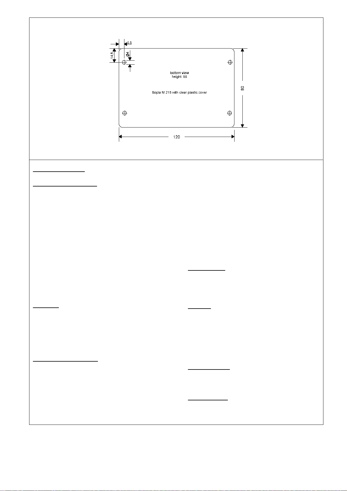
Dimensions:
Operating Manual
Mounting Instructions
The pin configuration is to be strictly observed.
The appliance is only to be operated with the
voltage entered on the rating plate. The glue
receptacle and the screening of the connection
lines are to be safety grounded. The probe- and
connection lines are not to be laid parallel to the
drive connections. The amplifier is not to be
installed onmachine components which are hot
and subjected to strong temperature
fluctuations. The probe distance to the vessel
wall must amount at least 30mm. The influence
of strong suction effect by cooling glue, can
conduct to material fatigue and in extreme
cases to probe destruction.
Function
The capacitive level sensor is provided for the
detection of insulant, solid and non-conducting
substances. The appliance evaluates the
capacity modifications ∆C of the probe base
capacity.
Adjustment/Operation
The adjustment of the appliance is simply to be
seen as a tolerance compensation. Resulting
from installation, filling media and the
fabrication, tolerances are given, which are so
compensated. The optimal shift-point is
10...30mm over the probe ground. On this point,
the glue altitude is to be adjusted. The
adjustment occurs, with the potentiometer
(level), over the probe sensitivity, and must
always be made with the effectively used filling
media. In direction of rotation to the right, the
glue level increases. In direction of rotation to
the left, the glue level decreases. With the
“time” potentiometer you can adjust the delay
time between0...5 sec. In the case of a possible
defect of the appliance, the exit can take any
conditionon.
Maintenance
The appliance is maintenance free. Appliances
are only to be repaired or touched up by the
manufacturer.
General
With installation and operation of the capacitive
level sensor, CNS-SV 25 T, the EU- and
national regulations must be considered. Our
appliances are on a high technical level.
Modifications, which serve the technical
progress, are reserved.
Met standards
EN 50081-1; EN 50081-2
EN 50082-1; EN 50082-2
EU-directives
89/336/EWG; 92/31/EWG; 93/68/EWG
Tippkemper Elektronik GmbH & Co KG
Zum Kreuzweg 12 D-59302 Oelde Tel. +49 (0) 25 29 / 93 01-50 Fax. +49 (0) 25 29 / 93 01-49
Other Tippkemper Accessories manuals


