Tiras ECD Tiras 1X User manual
FIRE ALARM SYSTEMS
ECD «Tiras 1X»
Installation Manual
DSTU ISO 9001:2015
Serial number:
FW Version:

2
Contents
1 List of abbreviations....................................................................................................................... 3
2 Terms and definitions .................................................................................................................... 3
3 General information and technical features............................................................................ 3
3.1 Purpose ......................................................................................................................................... 3
3.2 ECD technical features................................................................................................................ 5
4 ECD operation .................................................................................................................................. 6
4.1 Operation modes (conditions) ................................................................................................... 6
4.2 General operation algorithm..................................................................................................... 7
4.3 ECD inputs and outputs .............................................................................................................. 8
4.4 Controls and indication ............................................................................................................12
5 Installation and preparation for operation ............................................................................16
5.1 Installation .................................................................................................................................16
5.2 Inputs and outputs connection ...............................................................................................17
5.3 Preparation for operation........................................................................................................18
6 ECD setting......................................................................................................................................19
6.1 Access levels ...............................................................................................................................19
6.2 Default settings .........................................................................................................................19
6.3 Access Level 2 .............................................................................................................................19
6.4 Access Level 3 .............................................................................................................................20
6.5 TM keys assigning......................................................................................................................21
7 Maintenance...................................................................................................................................21
8 Packaging........................................................................................................................................22
9 Information on declarations of conformity to technical regulations and ......................22
10 Acceptance certificates .............................................................................................................22
11 Storage and transportation conditions .................................................................................22
12 Warranties and repairs..............................................................................................................23
13 Limitation of liability..................................................................................................................23
14 Disposal .........................................................................................................................................23

3
This guidance includes the description, operation principle, instructions on installation,
configuration and operation of Electrical Automatic Control and Delay Device (further - ECD)
Tiras-1X for use in fire alarm systems and in fire extinguishing systems.
In order to avoid possible errors during operation and possible damage to the
equipment, before the installation, configuration and operation of ECD, please read this
document and also the user manual, which are provided with the control panel.
1 List of abbreviations
FACP –Fire Alarm Control Panel;
FAS –Fire Alarm System;
AFAS –Addressable Fire Alarm System;
FARC –Fire Alarm Receiving Centre;
MRD –Manual Release Device;
EAD –Emergency Abort Device;
2 Terms and definitions
Zone –some defined part of the protected premises, in which one or more components
are installed and a general indication of the current state is provided for them.
Siren –sound or light and sound device intended to alert people to the need to evacuate
from areas where a fire has been detected.
Detector –component of the FAS that contains at least one sensor that monitors one
physical and (or) chemical phenomenon associated with fire continuously or periodically at
short intervals and emits at least one appropriate signal to the FCP.
Pre-discharge-warning time –time period between the start of the warning indication
and the discharge to warn personnel of impending gas release.
3 General information and technical features
3.1 Purpose
3.1.1 ECD is designed to detect the fire in two zones and control the devices for releasing
gas, powder and aerosol extinguishing agents in the fixed fire extinguishing system. ECD was
developed in accordance with the requirements of EN 12094-1:2015 "Fixed firefighting systems.
Components for gas extinguishing systems. Part 1. Requirements and test methods for electric
automatic control and delay devices " and EN 54-2:2003/Amendment No. 1:2012 "Fire detection
and fire alarm systems. Control and indicating equipment".
ECD is designed to control one direction of fire extinguishing.
It is allowed to use the ECD autonomously (in premises for which the current regulatory
documents do not require the FCAP using) or to be connected to the FAS based on FACP "Tiras
PRIME" or AFAS based on FACP "Tiras PRIME A".
The structural diagrams of the connection of the ECD to FCP are shown in Figure 3.1.

4
а) Connection of ECD to FCP «Tiras PRIME»;
б) Connection of ECD to FCP «Tiras PRIME A».
1 –detectors; 2 –manual call points; 3 –sirens; 4 –fire routing equipment (internal); 5 –EAD;
6 –MRD; 7 –release equipment; 8 –external power supply unit; 9 –fire routing equipment
(external); 10 –AM-Converter module (for connection to AFAS “Tiras PRIME A”).
Figure 3.1 –General structural diagrams of the connection of the ECD to FCP
3.1.2 ECD is designed to perform the following functions:
a) transmission of extinguishing signal to release equipment:
1) after reception and processing two independent input signals from two zones;
2) after reception and processing signal from FCP;
b) forming of delay of extinguishing signal (pre-discharge-warning time);
c) alert about the start of extinguishing;
d) forming of output signals about modes of operation;
e) manual release and emergency abort of extinguishing.

5
3.2 ECD technical features
General technical features of ECD are shown in Table 3.1.
Table 3.1 –Technical features of ECD
Feature
Value
Range of the power supply voltage of ECD («U1/U2» inputs), V:
- «12V»
- «24V»
11 –16
18,5 –30
Range of the power supply voltage for release equipment («UП+/ UП-»), V:
- «12V»
- «24V»
9 –16
18,5 –30
Maximum current consumption (Quiescent condition), mA
60
Maximum current consumption (Release condition), mA
80
Maximum load current of «П+/П-»outputs, А
- outputs are active for more than 5 s
- outputs are active for less than 5 s
5
10
Maximum load current of «U1», «SIR», А
0,5
Range of the voltage for controlled inputs/outputs, V:
- «12V»
- «24V»
9 –14,5
15 –27,5
Range of the current for controlled inputs/outputs (Quiescent condition), V:
- «12V»
- «24V»
1,1 –4,2
1,5 –8,4
Current limitation in controlled inputs/outputs, mA
58
“Open collector” outputs features («ГАС», «ВП», «AL», «FT», «ВА»):
Maximum load current, mA
Maximum voltage, V
Maximum load current for resettable fuses (each output), mA
150
30
200
Minimum inputs impedance, kOhm
50
Line resistance (wires), Ohm
250
Zone reaction time to alarm (fault), s, max.
10
Dimensions, mm
270 200 50
Weight, kg
0,6
Meantime to failure, hours, not less
40000
Average lifetime, years, not less
10
The ECD can be supplied from an external power supply source or from the power supply unit
of the FACP.
ECD is manufactured according to class B (DSTU EN 12094-1:2015), in a plastic case with a
protection degree IP30 according to IEC 60529:1989.
ECD is designed for continuous round-the-clock operation in premises with unregulated
climatic conditions. The range of operating temperatures is from -20 to 50 OC. The relative humidity
is no more than 93% at a temperature of 25 OC.

6
4 ECD operation
4.1 Operation modes (conditions)
- Quiescent (standby) –operating mode when the ECD is not in any of the following modes:
- Pre-activation –operating mode when the ECD received an activation signal from one of
the controlled zones or one signal from the FACP.
- Activation –operating mode when the ECD received activation signals from:
- both controlled zones,
- two zones of FCP Tiras PRIME or two detectors in FACP Tiras PRIME A zone,
- manual release input ("MANUAL RELEASE" button in the ECD front panel).
When the ECD in the "Activation" mode, the evacuation alert starts working in intermittent
mode and the extinguishing delay time (pre-discharge-warning time) counts down (if a delay is
set).
- Release (extinguishing) –the mode after extinguishing delay time has expired. In the
Release mode, an alert about the release of an extinguishing agent is activated and a signal is
transmitted to the extinguishing equipment.
- Release 2 –a special Release mode when the ECD goes under one of the following
conditions:
- after the "Activation" mode, confirmation of the release of the extinguishing agent was
received;
- received a signal about the spontaneous release of an extinguishing agent in the Quiescent
mode.
The signal about the release of an extinguishing agent is sent to the "KП" input (see
clause 4.3.6).
- Manual (Automatic disabled) –when the ECD ignores receiving activation signals from
controlled zones or from the FCP. Activation of the Release mode is possible only by activating
the manual release input or pressing the "MANUAL RELEASE" button (see p. 4.3.4).
- Fault –when a fault of at least one of the controlled functions or controlled circuits is
detected.
- Disabled –the mode when some functions are manually disabled, the ECD does not
process signals from disabled input circuits or does not issue control commands to disabled
outputs.

7
4.2 General operation algorithm
The general operation algorithm of the ECD is shown on Figure 4.1.
Figure 4.1 –The general operation algorithm of the ECD
8
4.3 ECD inputs and outputs
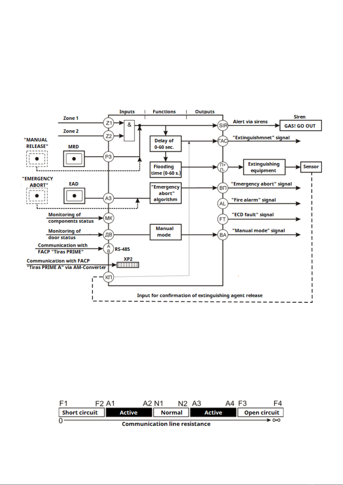
4.3.1 Operational diagram
The ECD operational diagram with the indication of inputs and outputs with their purpose,
is shown in Figure 4.2
Technical features of the ECD inputs and outputs are given in table 3.1.
The algorithms for determining the state of the ECD inputs and outputs depending on the
connected communication lines resistance are given in clause 4.3.2.
Inputs and outputs connection diagrams are given in Appendix A.
Figure 4.2 –The ECD operational diagram
4.3.2 Algorithm for determining the status of the inputs and outputs depending on
the connected lines resistance
The algorithm for determining the status of the controlled inputs and outputs depending
on the value of the resistance of the lines connected to the corresponding inputs is shown in
Figure 4.3 and in Table 4.1.
Figure 4.3 –A controlled inputs and outputs status change with a change in the
resistance of the connected communication lines

9
Table 4.1 –Thresholds for determining the status of controlled inputs and outputs
Controlled inputs and
outputs
Thresholds, kΩ
F1 –F2
A1 - A2
N1 - N2
A3 - A4
F3
«Z1», «Z2»
0 –0,5
0,6 –3,0
3,1 –8,7
-
> 8,7
«АЗ», «РЗ»
0 –0,7
0,8 –2,1
2,2 –8,7
-
> 8,7
«КП»
0 –0,7
0,8 –2,1
2,2 –8,7
8,8-14
> 14
«МК»
0 –0,7
-
2,2 –8,7
-
> 8,7
«П+/П-»
0 –6,3
-
6,4 –7,5
-
> 7,5
«SIR»
0 –4,5
-
4,7 –9,4
-
> 9,4
«ДВ»
-
0 –3,0
3,1 –8,7
> 8,7
-
4.3.3 «Z1» and «Z2» inputs (Fire alarm zones)
Inputs for receiving signals from fire detectors for automatic launch of extinguishing
work according to the "and" algorithm –the ECD goes into activation mode only if both inputs
are active (Fig. 4.4).
If the "РЗ" input is activated during the activation mode (pre-discharge-warning
time countdown), the ECD immediately switches to the Release mode.
Figure 4.4 –Algorithm when activating inputs "Z1" and "Z2"
4.3.4 «РЗ»input (Manual release)
Input for receiving signals from the MRD for manual launch of extinguishing. When the
«РЗ»input is activated in the Quiescent mode, a visual and audible indication of the input
activation appears on the ECD front panel ("MANUAL RELEASE" indicator, Table 4.2).
Note - pressing the "MANUAL RELEASE" button on the ECD front panel is equivalent
to activating the «РЗ»input.
If the input is activated in Quiescent mode, the ECD starts the pre-discharge-warning time
countdown.
The algorithm of the «РЗ»input is shown in fig. 4.5.
Figure 4.5 –The algorithm of the «РЗ»input
Activations of "Z1" and "Z2" inputs and «РЗ»input have the same priority.
4.3.5 «АЗ»input (Emergency abort)
Input for receiving signals from EAD for emergency abort of extinguishing. In the case of
the «АЗ»input fault (or communication line with the EAD fault), the ECD does not go into
Release mode.
10
Note - pressing the "EMERGENCY ABORT" button on the ECD front panel is
equivalent to activating the «АЗ» input.
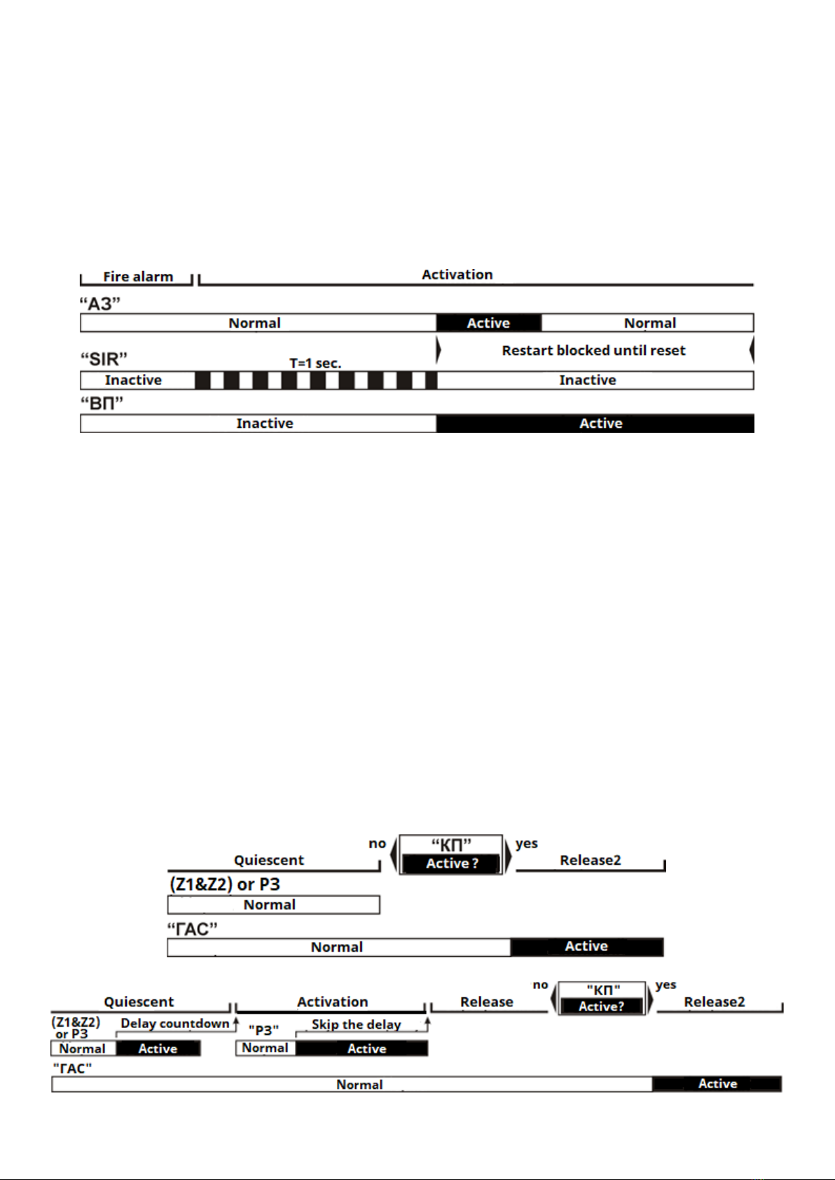
The algorithm of the «АЗ»login is shown in Fig. 4.6.
When activating the «АЗ»input (or pressing the "EMERGENCY ABORT" button from the
access level 2 (see p. 6.3), during the pre-discharge-warning time, the extinguishing signal is
blocked, "EMERGENCY ABORT" indicator lighting (Table 4.2). Transmission of the extinguishing
signal possible after the manual resetting of the ECD activation mode and receiving new
activation signals from Z1&Z2 inputs or «РЗ» input.
The algorithm for «АЗ»input and dependent outputs are shown in fig. 4.6.
Figure 4.6 –«Emergency abort»algorithm («АЗ»input)
4.3.6 «КП»input (Flow control)
If the design of the fixed fire extinguishing system provides for the function of controlling
the release of extinguishing agent, it is necessary to activate the "КП" input. The ECD is
switched to the Release mode after confirming the release of the fire-extinguishing substance
or a signal about its spontaneous release ("Release 2" mode - see point 4.1). Algorithms of the
ECD operation using the flow control function are shown in fig. 4.7, the indication is shown in
Table. 4.2.
Algorithms of the ECD operation with Flow control function:
a) in the ECD Quiescent mode when the "KP" input is activated (for example, spontaneous
release of a fire extinguishing agent occurred) - the ECD switches to the "Release 2"
mode and activates the evacuation alert (sirens) without activating the output to the
fire extinguishing equipment –"П+/П-" (Fig. 4.7 a);
b) upon activation from the inputs "Z1" and "Z2", or "РЗ", the ECD waits for a confirmation
signal about the release of the extinguishing agent at the input "КП", and only after that
the "Release 2" mode is set and the output "ГАС" is activated (Fig. 4.7 b).
а)
б)
Figure 4.7 –Algorithms with the Flow control function is enabled

11
If the "КП" input is faulty, the ECD works according to the usual algorithm (without
waiting for confirmation about the release of fire extinguishing agent).
4.3.7 «МК» input (Monitoring of status of components)
The «МК»input is used to detect the fault status of individual components of the fixed fire
extinguishing system and transmit it to the "FT" output. The "MK" input status does not affect
other functions or ECD operation algorithm.
The "MK" input can transmit the status of such components as: fire doors, dampers, weight
or pressure sensors of extinguishing equipment, etc. The number of connected outputs of the
components is according to the needs of the consumer, but it is necessary to ensure that the
operating conditions of the MK input are not violated (Table 4.1, Fig. 4.3)
4.3.8 «ТМ» input (Touch Memory)
The "TM" input is used to connect Touch Memory readers (1-wire, iButton), which enable
access to the Level 2 or remote activation/deactivation of the "Manual" mode. One key per
mode and no more than two keys per user can be used (see Table 6.1).
4.3.9 «ДВ» input (door status monitoring)
The «ДВ»input is used to connect opening detectors installed on the entrance door of
the premises. When the input is activated, the ECD switches to the "Manual" mode, the "ДВ"
and "MANUAL MODE" indicators light up (see Table 4.2). Exit from the "Manual" mode is
possible only from the access Level 2 of (see p. 6.3) by pressing the "MANUAL MODE" button
or applying the TM key.
4.3.10 «П+/П-» output (release equipment)
The output is intended for transmitting the launch signal to the extinguishing equipment,
as well as for monitoring the communication line between the ECD and the extinguishing
equipment. The output is activated in the "Release" mode. The output can be in an active state
from 1 to 60 s or until the reset procedure is performed after the extinguishing agent release
time has expired (see Table 6.1). The required activation time of the output should be selected
on the technical characteristics of the extinguishing equipment used.
4.3.11 «SIR» output (evacuation alert)
The output is intended for transmitting a signal to warning devices (sound and light),
which are intended to alert about preparation for the release of a fire-extinguishing agent
("Gas, exit!", "Aerosol, do not enter!", etc.), and about the release of a fire-extinguishing agent.
The output monitors the communication line with the sirens. The connection diagram is
shown in Fig. A.4 of Appendix A. The output has two operation modes that are set
automatically: intermittent and continuous.
Intermittent mode: turns on during the pre-discharge-warning time countdown, the
output is activated for 0.8 s with a period of 1.6 s (Fig. 4.6).
Continuous mode - the output is activated continuously, during the "Release" mode.
If the "SIR" output or the communication line with the sirens is failure, the "Release" mode
cannot be reached.
It is possible to disable the "SIR" output only after completing the "Release" or "Release 2"
mode (see p. 6.3.2).

12
Note - when the "SIR" output is disabled, the "П+/П-" output is automatically
disabled.
When the "П+/П-" output is enabled, the "SIR" output is automatically enabled, if it was
disabled before.
4.3.12 «ГАС» output
This "open collector" type output activates simultaneously with “П+/П-”output.
4.3.13 «ВП» output (Emergency abort)
The "open collector" type output activates when the "AЗ" input is activated or the
"EMERGENCY ABORT" button is pressed from the access level 2 (see item 6.3) and remains
active until manual reset (fig. 4.6).
4.3.14 «AL» output (Alarm)
The "open collector" type output activates when: any of the ECD zones are activated, the
"РЗ" input is activated, the "MANUAL RELEASE" button is pressed from the access level 2, or an
activation signal is received from the FCP.
4.3.15 «ВА» output (Manual mode)
The "open collector" type output activates when the ECD is going to the "Manual" mode.
4.3.16 «FT» output (Fault)
The "open collector" type normally closed output activates when fault of any of ECD
controlled function (circuits) is detected.
4.3.17 Power supply inputs
The ECD has several inputs for connecting an external power supply:
- "U1/U2" (main and backup) - for supplying the ECD and sirens;
- "UП+/UП-" - for supplying the output "П+/П-" to the fire extinguishing equipment.
These inputs can be connected to one common power supply unit or to several different
ones. The power supply unit should meet the requirements of DSTU EN54-4:2003 "Fire alarm
systems. Part 4. Power supply equipment (EN 54-4:1997, IDT). The voltage of the power supply
connected to the ECD and the fire extinguishing equipment must correspond to the values
indicated in Table. 4.1 depending on the programmed settings (table 6.1).
4.3.18 ECD connection to FCP «Tiras PRIME» and «Tiras PRIME A»interfaces
"A", "B" contacts are used to connect the ECD to the FCP "Tiras PRIME" via the RS-485
interface.
The ХР2 slot (Fig. A.1, Appendix A) on the ECD board is used to connect it via AM-Converter
to the address loop of the FCP Tiras PRIME A.
The messages specified in Appendix B are transmitted through the specified interfaces.
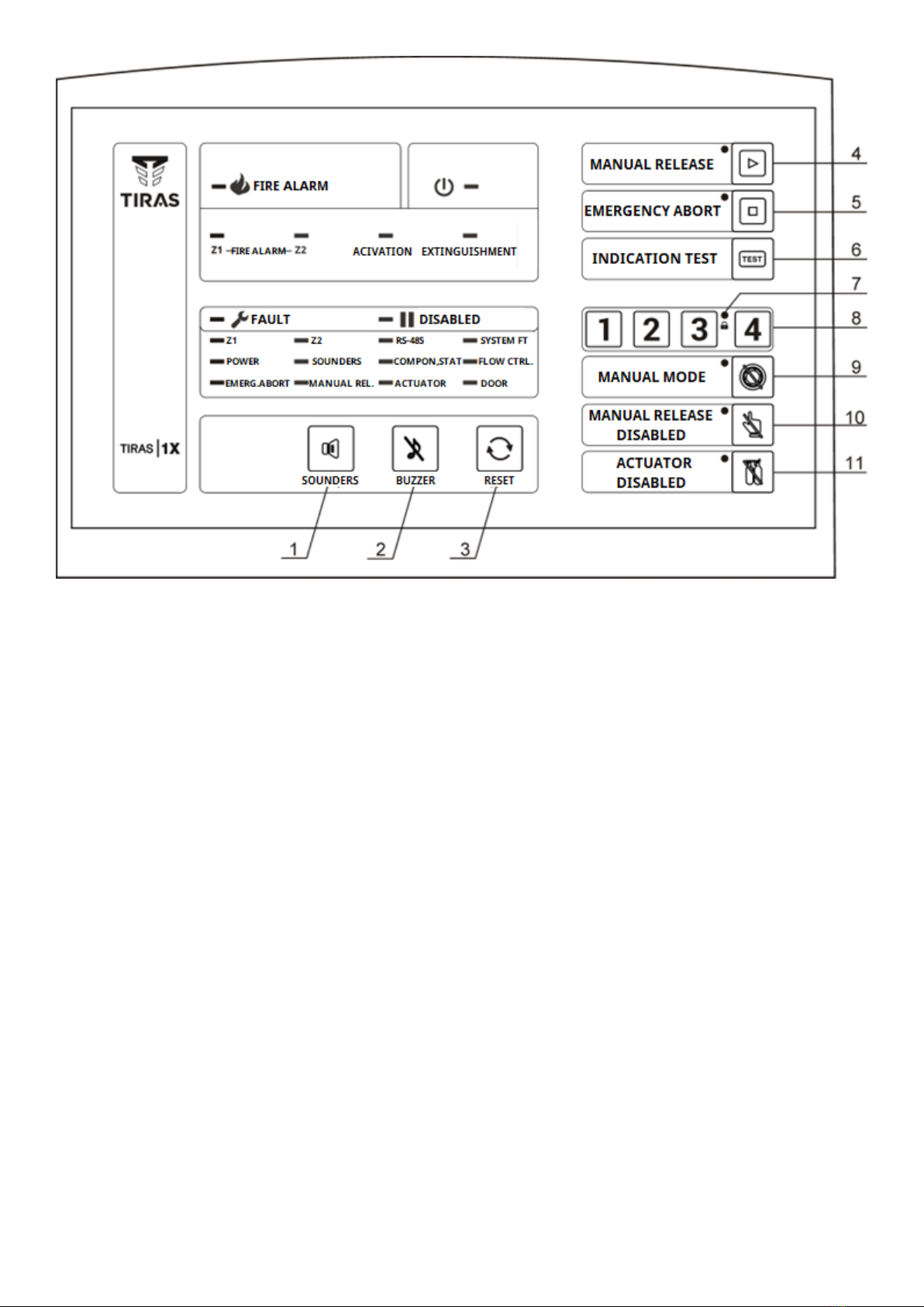
4.4 Controls and indication
The location of controls (buttons) and indicators on the ECD front panel is shown on
Figure 4.8.
13
1 –button to disable the "Sirens" output; 2 –button to turn off the internal sound indicator
(buzzer); 3 –reset button; 4 –button and indicator for activation of the "Manual release" function
(see section 3); 5 –button and indicator for activation of the "Emergency abort" function (see
section 3); 6 –the button for testing the indicators of the ECD (except for the "Access" indicator);
7 –"Access" indicator; 8 –buttons for entering the access code; 9 –button and an indicator for
“Manual mode” activation; 10 –button and indicator for disabling the "Manual release" function
(the "РЗ" input and the "Manual release" button); 11 - button and indicator for disabling the
output to the fire extinguishing equipment "П+/П-".
Figure 4.8 –User interface
Detailed information on the use of the ECD controls is given in section 6.
Information about the state of the indicators in the ECD operating modes is given in table 4.2.
Table 4.3 shows information on controls, their purpose and accompanying indicators.

14
Table 4.2 –ECD indications
Indicator name/
Purpose
Indicator status/mode
(Power, green)
Lighting - there is power supply at the ECD.
Blinking –one or more zones or a Manual release input has been activated, an
activation signal has been received from the FCP
Lighting - at least one of the ECD function is disabled.
Blinking –fault of one or more of the controlled inputs or outputs.
(Red, fire alarm)
Blinking –«Fire alarm»mode, an activation signal from one ECD zone or from
one FCP zone was received.
Lighting –activation signals from both ECD zones or from two FCP zones were
received.
(Pre-discharge-
warning time)
Blinking –«Activation»mode, the pre-discharge-warning tome is counting down
until Release mode.
Lighting –time is expired, the signal to the extinguishing equipment was
transmitted.
(“Release1” or
“Release2” mode)
Blinking - a signal to the extinguishing equipment was transmitted, but
confirmation of the release of the extinguishing agent at the "KП" input has not
yet been received (only if the“Flow control” is set – see Table 6.1).
Lighting - in the "Release" mode, if the “Flow control” is not set, or in the
"Release 2" mode, when the confirmation of the release of the extinguishing
agent has been received at the "КП" input.
After completion of the release time of the extinguishing agent (Table 6.1),
indicator is lighted off
Indicators of controlled inputs/outputs («Fault»/«Disabled»)
Blinking –a zone fault.
Lighting –a zone is disabled. In “Manual” mode both indicators lighting
(Communication
fault)
Blinking –the communication fault with FACP «Tiras PRIME».
Inactive –the communication with the FACP is normal or the ECD has not been
assigned to the FACP (works autonomously, without connection to the FACP).
Blinking –the ECD settings in memory were damaged or firmware failure
(see 3.4.4).
(Powersupplyfault)
Blinking –power supply fault: «U1/U2»or «UП+/ UП-» outputs voltage does
not meet with correspond values in the Table 3.1
(Siren output)
Blinking –sirens output or connection line fault
Lighting –the sirens output is disabled
(Monitoring of status
of components)
Blinking –the «МК»input connection line fault
Lighting –the «МК»input is activated (status of components was changed)
Blinking –the «КП» input connection line fault
Lighting –the «КП» input is activated
(Emergency abort)
Blinking –the «АЗ» input connection line fault
Lighting –the «АЗ» input is disabled.
(Manual release)
Blinking –the «РЗ»input connection line fault.
Blinking –the «П+ / П-» input connection line fault.
Lighting –the input is activated.

15
Table 4.3 –The ECD controls (buttons)
Button name
Purpose
Indicator status/Mode
Manual release
Blinking (red)–«РЗ» input
activation
Lighting (red) –«MANUAL RELEASE»
button was pressed.
Emergency abort of
extinguishing during the pre-
discharge-warning time
Blinking (yellow)–«АЗ»input
activation
Lighting (yellow) –"EMERGENCY
ABORT" button was pressed
during the pre-discharge-warning
time.
Manual/Automatic mode
switching
Lighting (yellow) –ECD –in
«Manual mode».
Disabling/Re-Enabling of
“Manual release” function
(input “РЗ” and “Manual
release” button)
Lighting (yellow) –«РЗ»output was
disabled.
Not lighting –«РЗ» output is
normal or was activated
Disabling/Re-Enabling of the
extinguish equipment output
(“П+/П-”)
Lighting –output was disabled.
Not lighting –«РЗ» output is
normal or was activated.
Buttons for entering the
access code and the "Access"
indicator
Lighting (green) –the correct
access code is entered or the
correct TM key is applied
Siren output (SIR) disabling
-
Buzzer turning off/on
-
Resetting of ECD modes
-
Testing of ECD status
indicators
-

16
5 Installation and preparation for operation
5.1 Installation
5.1.1 The design of the ECD allows it mounting on the wall. At the base of the ECD
enclosure there are 4 mounting holes and holes for cables entry (Fig. 5.1).
Figure 5.1 –The open ECD enclosure appearance

17
When entering cables, minimum gaps shall be provided between the edges of the holes
and the cables isolations. If any of the cable entry holes will not be used, do not break their
falseplates.
5.1.2 The enclosure cover with the control and indication board fixed on it opens from
the upper edge and turns down. To open, press one by one on the spring latches, which are
located in the holes on the side walls of the enclosure, starting from the upper ones (Fig. 5.2).
Figure 5.2 –ECD enclosure opening
If the ECD will be mounted on the wall, it is necessary to ensure the possibility of
convenient access to it.
5.2 Inputs and outputs connection
5.2.1 The ECD inputs and outputs should be connected in accordance with the project of
the fixed fire extinguishing system and the recommendations given in this passport.
If any of the inputs: "Z1", "Z2", "MK", "KП", "ДВ", "РЗ", "АЗ" will not be used, it should be
connected to the terminals "GND" through resistor 6.8 kΩ, 0.5 W.
WARNING! In order to prevent the failure of the ECD, it is necessary to limit the
current in the circuits connected to the "open collector" type outputs ("ГАС", "ВП", "AL",
"FT", "ВА") to the level of 150 mA (see Table 3.1, Fig. A6, A7 of Appendix A).
5.2.2 Connection diagrams of individual components of the fixed fire extinguishing
system to the ECD inputs and outputs are shown in figures A.2 - A.7 (Appendix A).
No more than 32 detectors can be connected to each of the inputs "Z1", "Z2".
WARNING! It is necessary to connect the fire extinguishing equipment ("П+/П-"
inputs) only with protective diodes, as shown in fig. A.5 of Appendix A.
5.2.3 Stranded or solid copper wires with a recommended cross-sectional area 0.22-
0.5 mm2should be connected to the input and output terminals (except those specified
in 5.2.3).

18
5.2.4 The power supply of the sirens and the fire extinguishing equipment should be
connected to the ECD terminals using of the copper wires with a cross-sectional area
corresponding to the current consumption.
The voltage of the power source connected to the ECD and the fire extinguishing
equipment must correspond to the values indicated in Table. 4.1 depending on the
programmed settings (table 6.1).
WARNING! The device and the power supply unit should be placed as close as
possible to the fire extinguishing equipment to ensure the minimum length of the
cables and, accordingly, reduce the voltage drop on the cables.
For example, with a distance from the power supply unit to the fire extinguishing
equipment of 50 m and a load current of 3 A, in a two-wires line with a cross section of
2.0 mm2, the voltage drop will be 2.8 V.
The power supply lines between the power supply unit and the ECD, which are outside
the enclosure and have a length of more than 10 cm, should be protected from mechanical
damage.
5.2.5 To connect to the "A", "B", "GND" terminals of the RS-485 interface, a "twisted pair"
type cable should be used. In conditions of significant industrial electromagnetic interference,
it is recommended to use a shielded cable. The shield should be connected to the grounding
terminals only at one of the two ends of the line (in the ECD it is the "GND" terminal).
5.2.6 The ECD has fire routing output “AL” (normally open) and fault routing output “FT”.
(normally closed) to transmit to the FARC respectively the fire alarm signal and the fault signal.
5.2.7 An example of connecting the ECD to the gas fire extinguishing system is shown in
fig. A.8, Appendix A.
5.3 Preparation for operation
5.3.1 After installing the ECD, the following actions should be carried out:
- in accordance with clause 6.2, reset the ECD to factory settings;
- enter the access level 3 of and set the parameters according to table 6.1;
- register the required number of Touch Memory keys according to clause 6.5;
- exit from the access level 3.
5.3.2 After installation and setting it is necessary to check the correctness of the ECD
operation:
- if fault indicators are flashing (table 4.2), it is necessary to establish and eliminate the
causes of faults;
- check the operation of the ECD according to the algorithm of fig. 4.1, as well as the
operation of each component connected to the ECD.
WARNING! In order to avoid incorrect operation of the fire extinguishing
equipment, the first switch-on and subsequent switches-on after changing of the ECD
settings should be carried out without connection to the extinguishing equipment, just
using load equivalents.
If, during the approving of the ECD operation, the "П+/П-" output does not activate, the
following causes should be checked:
- the "АЗ" input (emergency abort) is activated. The "АЗ" input has a higher priority than
the "РЗ" input (manual release);

19
- fault of the "AZ" input or its communication line;
- fault of the "SIR" output (sirens) or its communication line;
- the "ДВ" input is activated;
- the “П+/П-”output for the extinguishing equipment is disabled.
6 ECD setting
6.1 Access levels
Level 1 - allows you to receive information visually from the indicators, turn off the sound
(by pressing the "BUZZER" button), check the performance of the ECD indicators (by pressing
the " INDICATION TEST" button). Does not require user authorization.
Level 2 allows to perform the following operations:
- resetting the activation and release modes;
- disabling and re-enabling the siren output ("SOUNDERS" button);
- disabling and re-enabling the output to the fire extinguishing equipment (button
"ACTUATOR DISABLED");
- disabling the manual release input ("MANUAL RELEASE DISABLED" button);
- ECD switching to the "Manual" mode ("MANUAL MODE" button);
- ECD switching to the "Activation" mode ("MANUAL RELEASE" button);
- avoiding the ECD switching to the "Release" mode during the pre-discharge-warning
time ("EMERGENCY ABORT" button)
Access to the Level 2 is possible by entering an access code or applying a Touch Memory
key.
Level 3 is intended for setting the parameters of the ECD functions during
commissioning and maintenance.
Level 3 is available by means of the tools and can be additionally restricted by the ECD
tamper (disabled by default).
6.2 Default settings:
To reset the ECD to default settings^
- turn off the ECD power supply, if it is turned on;
- while holding down the "Reset" button, power on the ECD. After loading the settings,
the indicator «Access»( ) flashes for 3 seconds
6.3 Access Level 2
To access the Level 2, enter the access code or attach the Touch Memory electronic key
to the reader. If the entered access code is correct, the «Access»( ) indicator lights up. If the
key code is accepted, the reader's built-in indicator and the "Access" indicator on the ECD front
panel will light up.
Exit from access level 2:
- automatically after 5 seconds;
- after reset, shutdown or mode change;
6.3.1 Resetting
Features of the "Reset" function:
a) it is possible to switch the ECD to the Quiescent mode by pressing the "RESET" button
at any time, except for the "Release" and "Release2" modes.

20
b) in the "Release" mode, it is possible to switch the ECD to the Quiescent mode by
pressing the "RESET" button after the time of the fire-extinguishing agent release has expired
(Table 6.1, "Release time").
6.3.2 Disabling
Disabling used to prevent from receiving or transmitting signals on the input or output
(for example, during testing or maintenance).
Control of lines connected to the ECD is disabled or enabled by the corresponding
buttons, the indicator of disabled line lights up.
The ECD provides the disabling of the following inputs and outputs:
- "РЗ"–Manual release. If the " РЗ " input is disabled (by the "MANUAL RELEASE
DISABLED" button), the ECD does not respond to any of the states of this input or the
communication line, manual release becomes impossible;
- "П+/П-" –extinguishing equipment (by the "ACTUATOR DISABLED" button). Disabling
avoids the activation of the output to the fire extinguishing equipment;
- "SIR"–siren output (by the "SOUNDERS" button). When this output is disabled, the
"П+/П-" output is also automatically disabled in order to prevent fire extinguishing without
the alert. It is possible to disable the siren output only after the time required for the release
of the extinguishing agent has expired. In the "Activation" mode sirens are silenced by
pressing the "EMERGENCY ABORT" button.
6.3.3 Manual mode
The "Manual" mode is used to avoid the automatic activation in case of room leakage or
during the presence of personnel in the controlled premise.
To enable this mode, press the "MANUAL MODE" button, the " MANUAL MODE" indicator
and the general "DISABLED" indicator light up.
The ECD provides a function of avoid the start of fire extinguishing in the case of room
leakage by monitoring of the premise door status (for example, by means of magnetic
switches). The magnetic switches (detectors) connect to "ДВ" input. In the case of a fault or an
activation of the "ДВ" input, the ECD switches to the "Manual" mode. At the same time, the
"MANUAL MODE" indicator and the "DOOR" indicator light up.
In this mode, it is possible to activate the extinguishment only by the ECD "MANUAL
RELEASE" button or a MRD connected to the "РЗ" input.
6.4 Access Level 3
At the access level 3 it is possible to set the parameters of the ECD functions listed in
table 6.1.
To enter the level 3:
a) power off the ECD and the extinguishing equipment;
b) open the ECD enclosure;
c) connect the ECD to the PC using the USB-miniUSB cable or to smartphone using
additionally OTG cable;
d) launch the tLoader PRIME program, read the settings from the device, set the
necessary settings according to table 6.1 and write settings in the device;
e) disconnect the ECD from PC or smartphone.
Table of contents
Other Tiras Security System manuals


Popular Security System manuals by other brands

UTC Fire and Security
UTC Fire and Security Interlogix ATS1236 Installation sheet

Smart Hi-Tech
Smart Hi-Tech SMART GUARD user guide

Vimar
Vimar By-alarm 01715 quick start guide

Honeywell
Honeywell VISTA-128BPTSIA quick guide

Swann
Swann SW351-KCH operating instructions

Elan
Elan EL-IP-OTF2-SS quick start guide


