Tire-Safeguard TPM-V104-R50H User manual
Tire-Safeguard
Tire Pressure Monitoring System
TPM-V104-R50H Model
Operator’s Manual
HCI Corporation
Version 1.0 1 TPM-V104 Op Manual
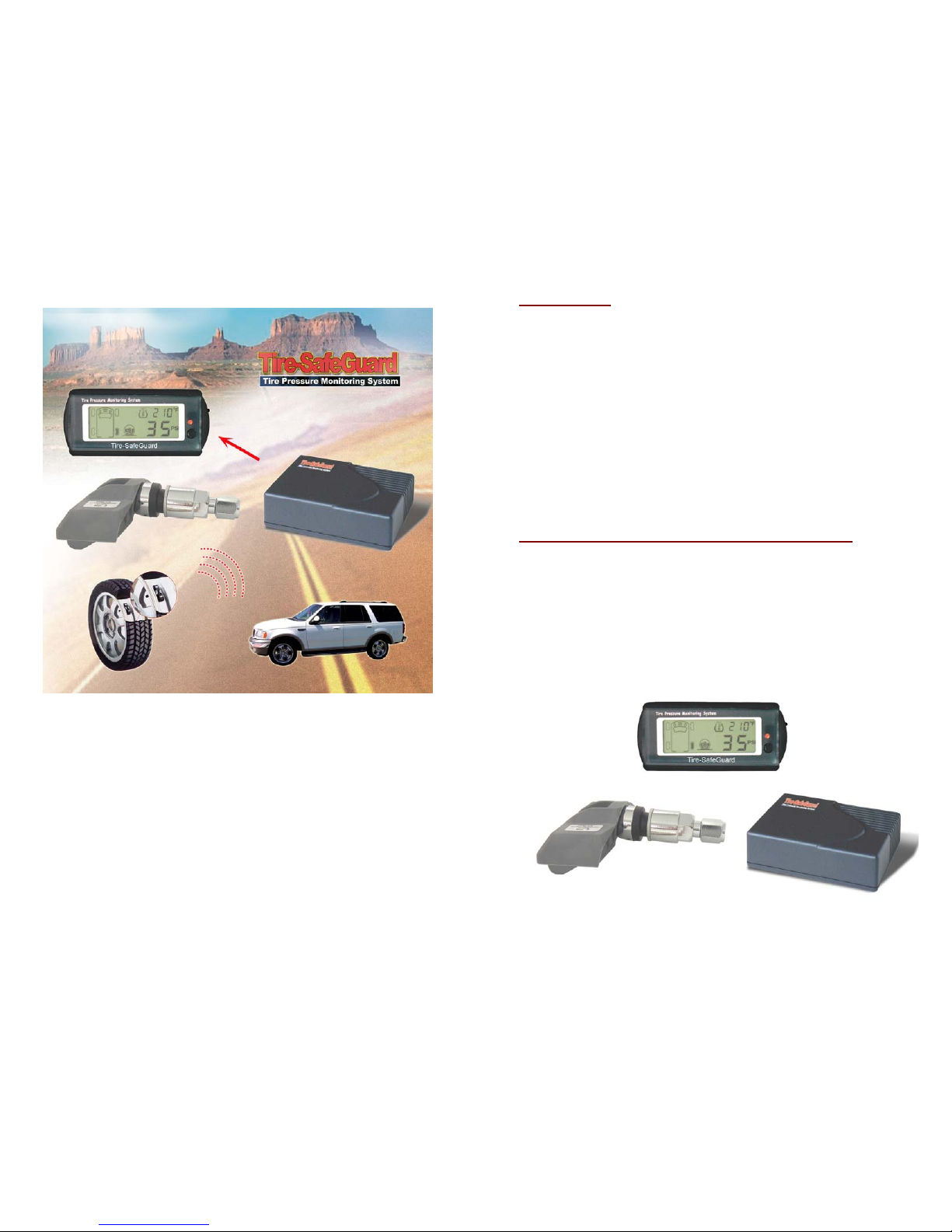
1. Introduction
Tire-Safeguard is a wireless tire pressure monitoring system. This
valuable addition to your vehicle will help you drive safer. Tire-
Safeguard automatically monitors your vehicle tires, and will
immediately alert you of abnormal tire pressure and/or temperature,
providing a timely warning to you in order for you to take corrective
action. In addition, Tire-Safeguard’s digital display makes tire pressure
maintenance easy. You will no longer need to manually check the tires
with a pressure gauge. Consequently, your tires can easily be kept in
optimal operating condition. The resulting benefits are obvious:
reduced uneven tire wear, reduced severe tire damages, reduced air
loss related tire failures, increased tire life, improved fuel efficiency,
improved vehicle braking and handling. Best of all, Tire-Safeguard will
help you drive with enhanced vehicle safety and with less worry of flat
tires and blowouts.
2. Tire Pressure Monitoring System (TPMS) Overview
The major components of Tire-Safeguard TPMS are: one sensor-
transmitter per tire, a receiver, and a display. For the internal valve-
mounted model, the sensor-transmitter is affixed inside the tire on the
wheel with a valve stem. The sensor-transmitter automatically and
continuously monitors the tire and, periodically, transmits out RF
signals with the current tire pressure and temperature readings. Upon
detection of abnormal tire pressure and/or temperature, the sensor-
transmitter will immediately issue a warning signal. The receiver
captures the signals from the sensor-transmitters and forwards them to
the display unit.
Version 1.0 2 TPM-V104 Op Manual
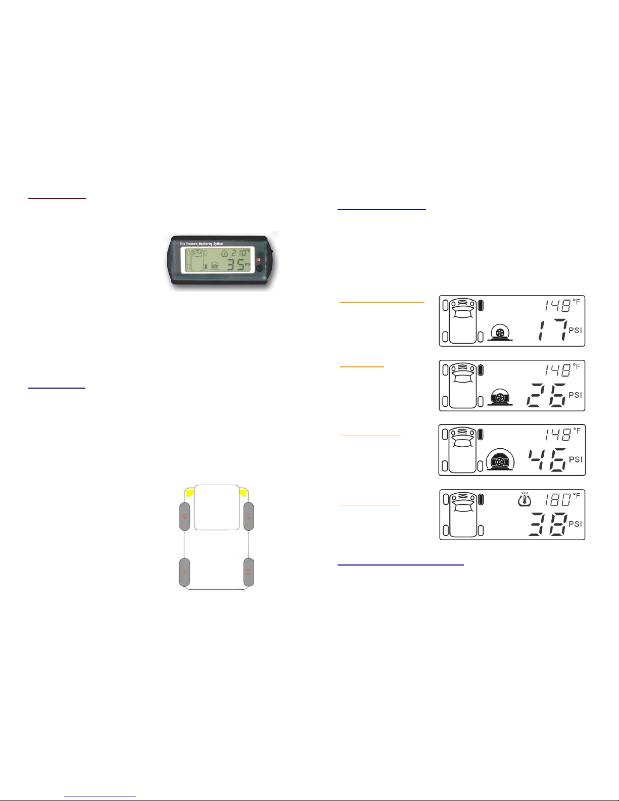
3. The Display
The display unit is the interface between the TPMS and the user. The
display has a graphical representation of the vehicle with tire icons on
the left side of the screen, a
thermometer icon and
temperature reading on the upper
right, and a tire status icon and
pressure reading on the lower
right side.
There is a status lamp on the right
side of the display. Below the status lamp there is a control button.
Pressing the control button will display individual tire pressure and
temperature readings; a darken tire icon on the vehicle graphic
indicates the associated tire location.
On the right edge of the display unit there is a button for programming
the system. Detail description of the set up procedures will be
described in a later section.
3. 1 Operation
After installation, the system operates automatically and continuously.
When vehicle power is turned on, the display will show the current tire
pressure and temperature one-by-one from tire No.1 to No. 4. The
display then turns off and only the status light remains lit. A green
status light indicates normal pressure and temperature for all tires.
Otherwise the status light turns to blinking red (low tire pressure
and/or rapid air loss) or red (other warnings), and the corresponding
tire indicator(s) and the warning icon(s) will be illuminated.
The order of tire information
display for a 4-tire vehicle is
as showed on the right.
Version 1.0 3 TPM-V104 Op Manual
3. 2 System Warnings
Upon detection of abnormal tire pressure and/or temperature the
system will display one of the following warnings and the status light
will change to red or blinking red as described earlier. The warning
display lasts 8 seconds and then will switch to a screen as shown in
Abnormal Situation Display (described in the next section). For severe
warnings (low pressure and rapid pressure change) the system will
also sound an 8-second alarm.
Low pressure or blowout
The tire icon is hollow;
indicating tire pressure is
low or tire is rapidly
losing 3+ PSI of air within
a number of seconds.
Slow air leak
The tire icon is 2/3 full;
indicating tire pressure
depletion of 3 PSI or
more within 2 to 10
minutes.
High tire pressure
The tire icon is full with
an outer shell; indicating
the tire pressure is too
high.
High temperature
The high-temp icon is
visible; indicating tire
temperature is too high.
3.3 Abnormal Situation Display
A persistent abnormal tire situation (with possibly several tire
abnormalities) will cause one of the following warnings to be displayed.
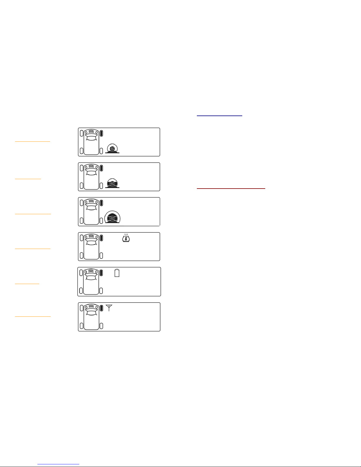
Version 1.0 4 TPM-V104 Op Manual
The warnings are listed below in the order of precedence for display
selection (from multiple abnormalities) by the system.
Low tire pressure
(Highest priority)
Slow air leak
High tire pressure
High temperature
Low Battery
No Sensor Signal
(Lowest priority)
Version 1.0 5 TPM-V104 Op Manual
3.4 Display Control
•A warning will continue to be displayed until the cause of the warning
is corrected.
•When multiple warnings occurred, the higher priority warning will be
displayed first.
•Pressing the Control Button for 3 seconds will clear the warning
display.
•If the abnormal situation persists, however, warnings will be
displayed again even after the display was cleared.
•The system continues to monitor the tires even after the vehicle is
turned off. When the vehicle’s power is turned back on, the current
tire information is displayed.
4. Warning Threshold Set Up
The user can adjust the warning threshold for tire pressure and
temperature, as follows:
•Press and hold down the Setup Button located on the side of the
Display. While holding down the Setup Button, turn the vehicle’s
power on. After 3 seconds the system enters the Warning Setup
Mode. Release the Setup Button.
•The first screen is for setting up the Low Pressure warning
threshold. Pressing the Setup Button again brings up the next
screen (High Pressure).
•While in a setup screen, the Control Button on the front panel is
used to change the threshold setting. Pressing and holding down
the Control Button advances the setting rapidly.
•While in a setup screen, pressing the Setup Button exits the
setup. While in the last screen (High Temperature), pressing the
Setup Button exits the Warning Setup Mode and saves the new
settings for all screens.
•Turning vehicle’s power off before exiting the last screen always
cancels the setup.

Version 1.0 6 TPM-V104 Op Manual
5. Retrain System after Tire Change and/or Rotation
Alter the tires have been changed and/or rotated the system must be
retrained to display the correct tire locations, as follows:
5.1 Retrain System for All Tires
•Press and hold down the Setup Button. Turn on vehicle power.
After 6 seconds the system enters the Setup screen; the #1 tire
indicator starts blinking.
Setup Screen:
•Setup Steps -
¾Release 3 PSI or more of air from the #1 tire. This triggers its
sensor to send out a signal. Upon receiving the signal, the
system sets up this tire as the #1 tire location. The system
then moves on to the #2 tire.
¾Repeat the above step for the remaining tires (The setup order
must always be from tire #1, #2, …, to the last tire). After
successfully retraining the last tire the system exits the Setup
mode automatically.
¾A simpler way of retraining is: put the system to retraining
mode, follow the setup order and release air from each tire for
20 seconds without needing to look at the display. After
working on the last tire the retraining will be completed.
¾Refill tires to the proper air pressure.
¾Turning vehicle power off before finishing always cancels the
setup.
Setup Button
Control Button
Version 1.0 7 TPM-V104 Op Manual
5.2 Retrain System for Some Tires
•To retrain system for tire rotation or replacement with less than
all the tires, get into the Setup screen as described above, press
the Control Button to move the blinking icon to the desire tire
location, and then release the associated tire air as described
earlier to set it up.
•Note that each skipped tire will retain its previous location
assignment.
•If there are more tire setup then press the Control Button again
for moving the blinking icon to the next desire tire location, and
then repeat set up procedure.
•Press the Control Button passing the last tire icon to exit the
setup and save the new setting.
•Turning vehicle power off before finish always cancels the setup.
Popular Automobile Accessories manuals by other brands

Pacbrake
Pacbrake HP10216 installation manual

Witter
Witter ZX302/EU Fitting instructions

Hama
Hama 00 123530 operating instructions

Hamron
Hamron 003-067 operating instructions

Whelen Engineering Company
Whelen Engineering Company 10” Continuum Single installation guide

Brink
Brink 742828 29180527 installation instructions


