tissin TS900 Series User manual

Smart Valve Positioner
TS900
Series
Instruction Manual
Ver. PM-TS900EN-4/2018

2
Smart valve positione
r
TS900 Series tissin
Table of Contents
1 Introduction------------------------------------------------------------------------------------- 4
1.1 General information for the user---------------------------------------------------------- 4
1.2 Requirement for safety---------------------------------------------------------------------- 5
1.3 Basic safety instructions for use in the Ex area--------------------------------------- 6
2 Description of products-------------------------------------------------------------- 7
2.1 Function--------------------------------------------------------------------------------------- 7
2.2 Features--------------------------------------------------------------------------------------- 7
2.3 Options---------------------------------------------------------------------------------------- 7
2.4 Applications---------------------------------------------------------------------------------- 7
2.5 Name plats----------------------------------------------------------------------------------- 8
2.6 Products number---------------------------------------------------------------------------- 9
2.7 Specifications-------------------------------------------------------------------------------- 10
2.8 Structure-------------------------------------------------------------------------------------- 11
2.8.1 External structure----------------------------------------------------------------- 11
2.8.2 Internal structure------------------------------------------------------------------ 12
2.9 System configuration---------------------------------------------------------------------- 13
2.10 Principle of operation---------------------------------------------------------------------- 13
2.11 Dimension drawings----------------------------------------------------------------------- 14
2.11.1 Dimension------------------------------------------------------------------------- 14
2.11.2 Feedback shaft connection---------------------------------------------------- 14
3 Installation--------------------------------------------------------------------------------------- 15
3.1 Before installation----------------------------------------------------------------------------- 15
3.2 TS900L installation--------------------------------------------------------------------------- 15
3.2.1 Notes on installation --------------------------------------------------------------- 15
3.2.2 Effective rotation angle of feedback lever------------------------------------ 16
3.2.3 Lever type and dimensions ------------------------------------------------------ 16
3.2.4 Bracket installation----------------------------------------------------------------- 17
3.2.5 Dimension after installation------------------------------------------------------ 17
3.3 TS900R installation--------------------------------------------------------------------------- 18
3.3.1 TS900R installation examples--------------------------------------------------- 18
3.3.2 TS900R List of supplied installation parts----------------------------------- 18
3.3.3 TS900R installation steps-------------------------------------------------------- 19
3.4 Installation of option modules ------------------------------------------------------------- 21

3
Smart valve positione
r
TS900 Series tissin
3.4.1 Installation of Position transmitter module------------------------------------ 21
3.4.2 Installation of HART communication module-------------------------------- 21
3.5 How to adjust Auto/Manual switch ------------------------------------------------------- 22
4 Pneumatic connection---------------------------------------------------------------- 23
4.1 Condition of air supply----------------------------------------------------------------------- 23
4.2 Description of air ports----------------------------------------------------------------------- 23
4.3 Air connection---------------------------------------------------------------------------------- 24
4.3.1 TS900L air connection------------------------------------------------------------ 24
4.3.2 TS900R air connection------------------------------------------------------------ 24
5 Electrical connections---------------------------------------------------------------- 25
5.1 Terminal description-------------------------------------------------------------------------- 26
5.2 Power and Feedback signal connections----------------------------------------------- 27
5.3 Alarm switch connection-------------------------------------------------------------------- 27
6 Calibration--------------------------------------------------------------------------------------- 28
6.1 Description of Display----------------------------------------------------------------------- 28
6.2 Description of Buttons----------------------------------------------------------------------- 29
6.3 How to perform fast auto calibration ---------------------------------------------------- 30
6.3.1 Steps of auto calibration ---------------------------------------------------------- 30
6.4 Software map---------------------------------------------------------------------------------- 31
6.5 Description of Main menus----------------------------------------------------------------- 32
6.6 Description of Main parameters----------------------------------------------------------- 33
6.7 Description of Submenus------------------------------------------------------------------- 34
6.7.1 TUNNING ---------------------------------------------------------------------------- 34
6.7.2 PARAMETE-------------------------------------------------------------------------- 36
6.7.3 DEVICE P----------------------------------------------------------------------------- 38
6.7.4 INFOMATN--------------------------------------------------------------------------- 41
6.7.5 DIAGNOST--------------------------------------------------------------------------- 42
6.7.6 EMERGNCy-------------------------------------------------------------------------- 45
7 Error code and Troubleshooting -------------------------------------------- 46
8 Limited warranty and disclaimer -------------------------------------------- 47

4
Smart valve positione
r
TS900 Series tissin
1 Introduction
1.1 General information for the user
This instruction includes installation, operation, maintenance, and parts information for Tissin
TS900 Valve Positioner. Keep these instructions in a location which is easily accessible to
every user and make these instructions available to every new owner of the device.
Installation, commissioning and maintenance of the product can only be performed by
trained specialist personnel who have been authorized by the plant operator to do so.
To avoid possible injury to the personnel or damage to valve parts, WARNING,
CAUTION and NOTICE must be strictly followed.
Before installing or commissioning, be sure to read and thoroughly understand the
product manual and operate the product properly.
Operators must strictly observe the applicable national regulations with regards to
installation, function tests, repairs, and maintenance of electrical products.
For additional information or if specific problems occur that are not explained in these
instructions, contact the manufacturer.
The manual can be altered or revised due to hardware of software upgrades without any prior
notice. Please visit our website (http://www.tissin.co.kr ) and check the latest documentation.
Manual version PM-TS900EN-4/2018
Software version V.1.39

5
Smart valve positione
r
TS900 Series tissin
1.2
Requirements for safety
This manual contains notices you have to observe in order to ensure your personal safety, as
well as to prevent damage to property. These safety instructions are intended to prevent
hazardous situations and/or equipment damage. For the safety, it is important to follow the
instructions in the manual.
WARNING
Failure to observe the warning may result in serious injuries or death.
CAUTION
Failure to observe this warning may result in damage to the device or personal injury.
NOTICE
Failure to observe the warning may result in damage to the device or may degrade
performance.
Safety notes
CAUTION
Only trained and authorized person should operate the machinery and the equipment.
Do not use this positioner out of the range of its specifications as this can cause failure.
Do not service or attempt to remove product and machinery/equipment until safety is
confirmed.
Never handle mechanical equipment or disassemble the device until safety is confirmed.
Before loosening the pneumatic lines and valves, turn off the pressure and vent the
pneumatic lines.
Before reaching into the device or the equipment, switch off the power supply and
secure to prevent reactivation.
Observe applicable accident prevention and the safety regulations for electrical
equipment.

6
Smart valve positione
r
TS900 Series tissin
1.3
Basic safety instructions for use in the Ex area
To prevent the risk of explosion, observe not only the basic safety instructions in the
respective operating instructions for operation in the Ex area, but also the following.
WARNING
Make sure that the device is suitable for the area of use. Available in Zones 1 and
Zone2.
Check the positioner’s certified and permitted explosion proof range.
Close all unnecessary cable glands with lock screws approved for the explosions area.
Do not remove terminal cover in a hazardous location while the power is on.
Covers for the terminal and body should be in place while operating.
Install cables and conduit connections must accordance with IEC60079-14.
Ring terminal with surface area of more than 0.195mm
2
with M4 spring washer should
be used when connect the power.
For external ground terminal, ring terminal with surface area of more than 5.5 mm
2
should be used.
The external control unit should be installed a fuse with a rated short-circuit of current
of less than 62mA.
Do not disassemble the bolts and parts shown below when the power is connected.

7
Smart valve positione
r
TS900 Series tissin
2 Description of products
2.1 Function
Smart valve positioner TS900 series controls the valve stroke in response to an input signal of
4~20mA DC from the control panel, DCS or calibrator.
2.2 Features
LCD and 4 button local control
Quick and easy calibration
PST and alarm function
Auto / Manual switch included
Built-in self-diagnostic function
Modularization of the internal parts
IP66 / NEMA4X
Improvement of valve control speed by applying large flow pilot valve
Strong vibration resistance and impact resistance
2.3 Options
Position transmitter (4~20mA DC Feedback signal)
HART communication (Ver. HART 7)
Alarm sensor
2.4 Applications
The TS900 is mounted on a pneumatic control valves and is used for fluid control of industrial
parts.
Oil and gas
Chemicals
Power plant
Paper
Water treatment
Pharmaceutical
Printing and dyeing processing
Food and beverage
Other
8
Smart valve positione
r
TS900 Series tissin
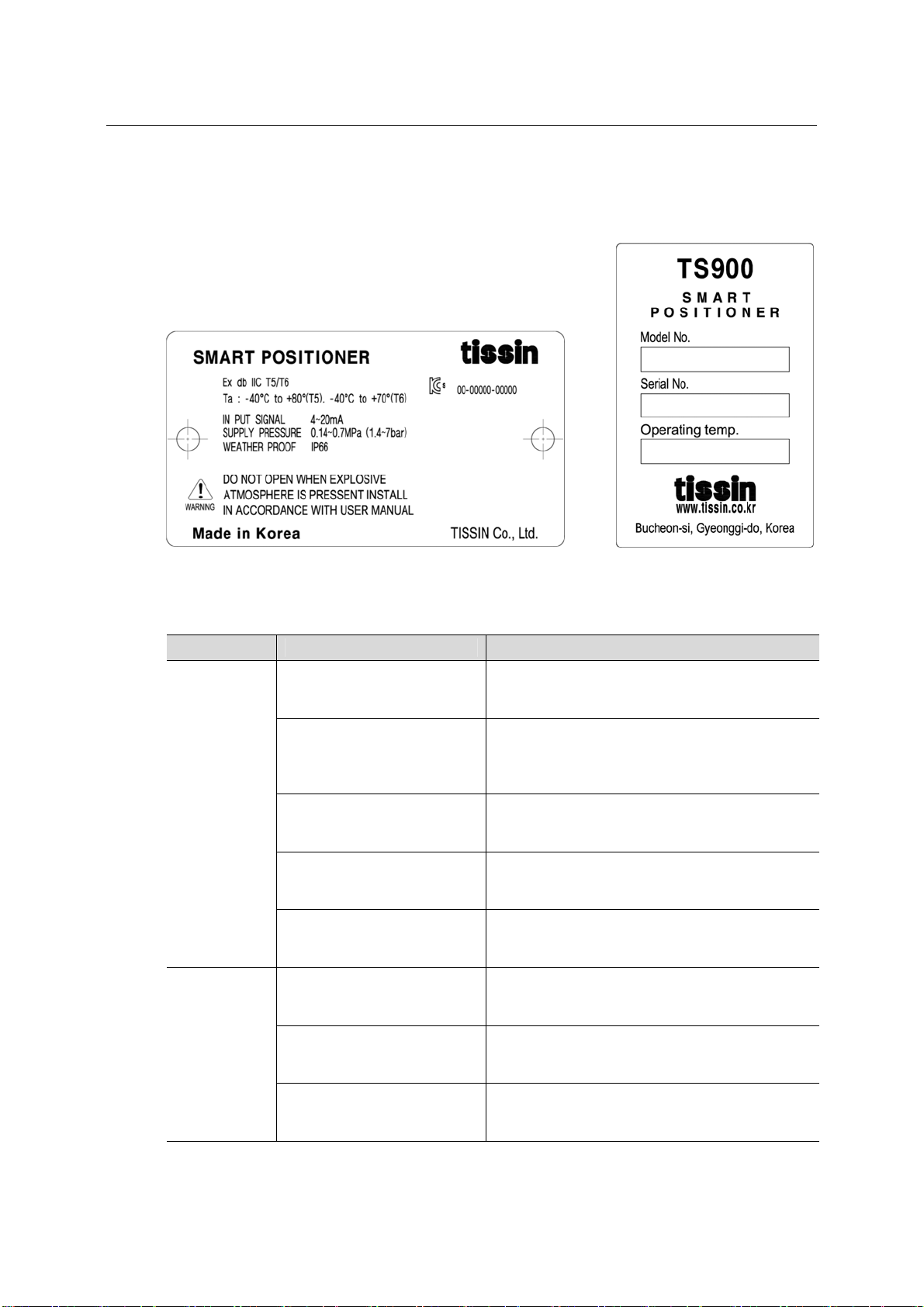
2.5 Name plates
<Body label> <Cover label>
Label Item Description
Body label
Ex db IIC T5/T6 Indicates the certified explosion proof grade.
Ta : -40℃to +80℃(T5)
-40℃to +70℃(T6)
Indicates the ambient temperature range for
the explosion proof. This temperature range
must be observed when using in explosion-
proof areas.
INPUT SIGNAL Indicates input current signal range.
SUPPLY PRESSURE Indicates the allowable input supply pressure
range.
WEATHER PROOF Indicates the enclosure grade.
Cover label
Model No. Indicates the model number.
Serial No. Indicates the serial number.
Operating Temp. Indicates the allowable operating
temperature.

9
Smart valve positione
r
TS900 Series tissin
2.6 Products number
TS900
Model Standard type TS900
Stainless steel TS905
Acting type Linear type L
Rotary type R
Explosion proof
type
Ex db IIC T5/T6 C
Connection type Conduit entry Air connection
G(PF)1/2 PT1/4 1
G(PF)1/2 NPT1/4 2
NPT1/2 NPT1/4 3
M20 NPT1/4 4
Lever type
(Linear ) 10~80mm 1
70~150mm 2
Adapter type(70mm) 3
Lever type
(Rotary) M6 x 34L (Fork lever type) 1
NAMUR 5
Ambient Temp. -30℃~80℃(Standard type) S
-40℃~80℃(Low temperature type) L
Communication*None 0
Position transmitter(4~20mA DC) 1
HART 2
HART and Position transmitter (4~20mA DC) 3
Alarm switch None 0
Included A

10
Smart valve positione
r
TS900 Series tissin
2.7 Specifications
Model TS900 TS905
Input signal 4~20mA DC
Impedance 500Ω(20mA DC)
Supply pressure 0.14~0.7MPa
Stroke Linear type:10~150mm, Rotary type:0~900
Air connection PT1/4, NPT1/4
Gauge connection PT1/8, NPT1/8
Conduit G(PF)1/2, NPT1/2
Explosion proof type Ex db IIC T5/T6
Degree of protection IP66
Ambient
Temp.
Acting Temp. -30℃∼85℃(Standard type),
-40℃∼85℃(Low temp type)
Explosion Temp. -40℃~60℃(T5) / -40℃~40℃(T6)
Linearity ±0.5% F.S.
Sensitivity ±0.2% F.S
Hysteresis ±0.5% F.S
Repeatability ±0.3% F.S
Air consumption Below 2.3LPM (Sup.=0.14MPa)
Required air quality Class 3 (ISO 8573-1)
Flow capacity Over 100LPM (Sup.=0.14MPa)
Material Aluminum die cast Stainless steel 316
Weight 3.5kg 7kg
Option specifications
Options Item Specification
HART HART version HART 7
Position transmitter Wire connection type 2Wire
Supply voltage 9~30V DC
Alarm switch Supply voltage 9~30V DC
Note: Please contact our sales department for other specifications.

11
Smart valve positione
r
TS900 Series tissin
2.8 Structure
2.8.1 External structure
.
①Body cover
②LCD window
③Button cover
④Buttons
⑤Junction box cover
⑥Feedback lever
⑦Ground bolt
⑧Conduit
⑨Water vent hole
⑩Auto/Manual switch
⑪Air supply port
⑫Air vent hole cover
⑬OUT2 gauge
⑭OUT1 gauge
⑮Pilot valve cover
○
16
Out1 port
○
17
Out2 port
12
Smart valve positione
r
TS900 Series tissin
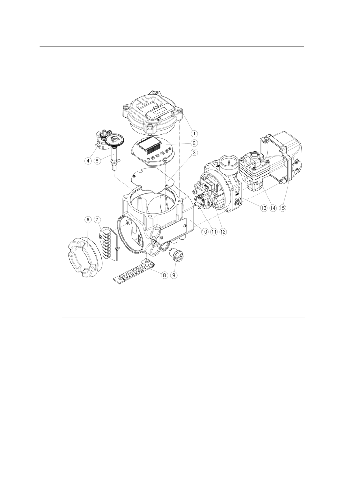
2.8.2 Internal structure
①Body cover
②Main PCB
③PCB support
④Potentiometer
⑤Main shaft
⑥Junction box cover
⑦Terminal block
⑧Feedback lever
⑨Water vent cover
⑩Body
⑪Pressure sensor (Option)
⑫Torque motor
⑬Pneumatic piping block
⑭Pilot valve
⑮Pilot valve cover
13
Smart valve positione
r
TS900 Series tissin
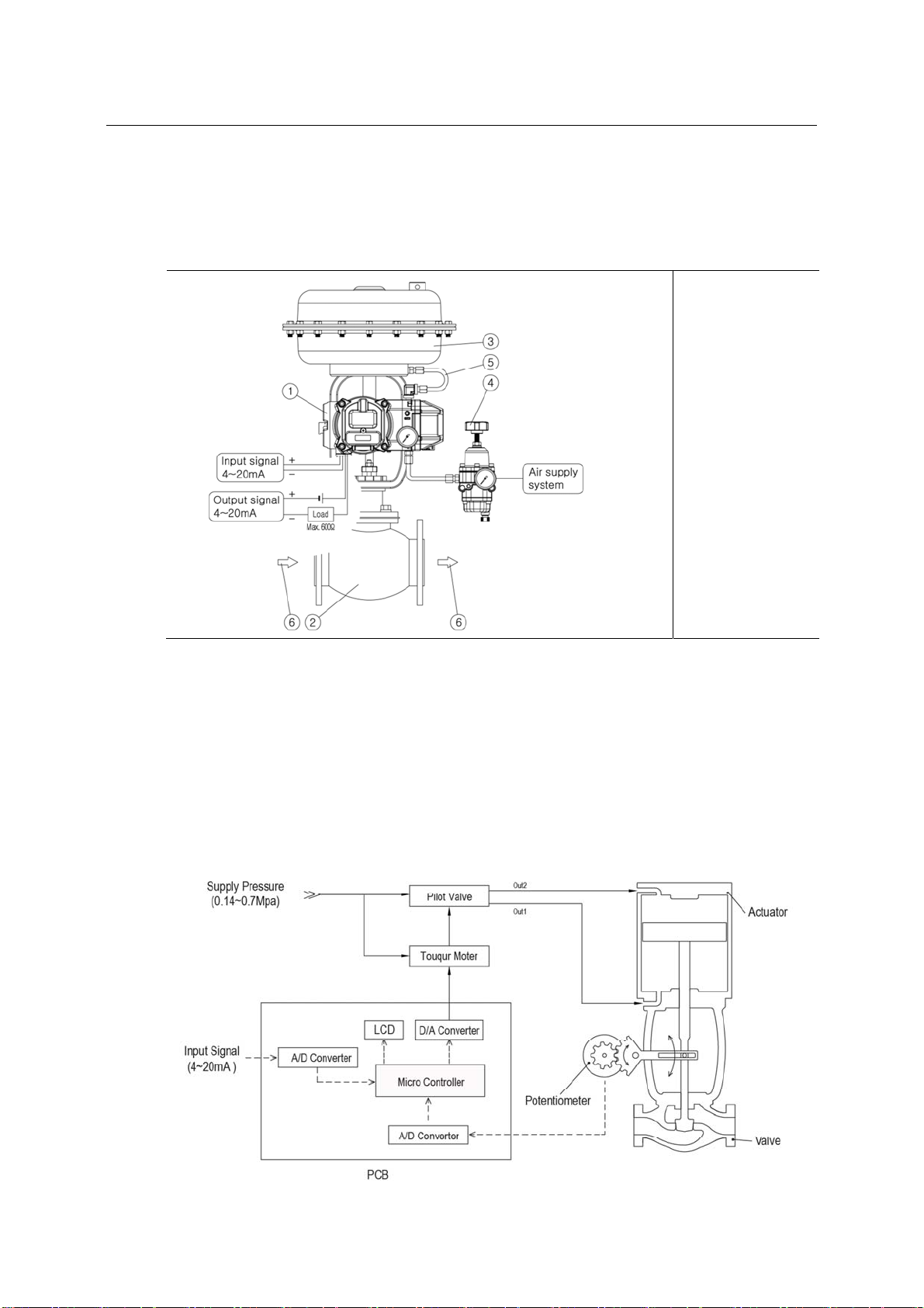
2.9 System configuration
Basically, the control valve system consists of a positioner for controlling the pneumatic
pressure of the actuator, an actuator for controlling the opening of the valve, and a valve for
controlling the flow of the fluid.
①Positioner
(TS900)
②Valve
③Actuator
④Regulator
⑤Out1 vent line
⑥Fluid
2.10 Principle of operation
TS900 receives the 4-20mA input signal of the control room, the micro-processor (CPU)
compares input signal with position feedback through the potentiometer and sends control
signal to the I/P conversion module torque motor, torque motor converts it to a pneumatic
signal to control the pilot valve to control the opening of the control valve by converting the
output pressure of OUT1 and OUT2.

14
Smart valve positione
r
TS900 Series tissin
2.11 Dimension drawings
2.11.1 Dimension
2.11.2 Feedback shaft connection

15
Smart valve positione
r
TS900 Series tissin
3 Installation
3.1 Before installation
WARING
Make sure if TS900 is appropriate to the valve and actuator installation conditions and
the site requirements specifications before installation.
If the installation state is not correct, TS900 control characteristics may be degraded.
3.2 TS900L installation
3.2.1 Notes on installation
When make the mounting bracket and connecting the lever to the stem connection pin, be
sure to observe the following two points.
If not compliance will affect the product performance such as linearity.
NOTICE
①When the valve stroke is 50%, the feedback lever should be horizontal.
②When the valve stroke is 50%, the stem connection pin must be located at the numeric
position marked on the feedback lever that is corresponding to the valve stroke.
①Feedback lever
②Stem connection pin
③Pin fixing spring
④Actuator stem
⑤Valve opening indicator

16
Smart valve positione
r
TS900 Series tissin
3.2.2 Effective rotation angle range of the feedback lever
The effective rotation angle of TS900L lever is respectively 30
o
upward and downward that is
based on horizon.
Follow 3.2.1notes, effective rotation angle can be maintained to achieve the best performance.
3.2.3 Lever type and dimensions
The numeric position marked on the feedback lever correspond to the valve stroke, and the
stem connection pin must be connected to the corresponding marked location
Lever No. Valve stroke Dimensions
No.1 10~80mm
No.2 70~150mm
No.3 10~70mm
NOTICE
If the rotation angle range is too small during operation, the performance of products
such as linearity may be degradation.
If the rotation angle range is too big during operation, may damage the product or cause
malfunctions.

17
Smart valve positione
r
TS900 Series tissin
3.2.4 Bracket Installation
Refer to the TS900L drawing (refer to 2.11.1) and actuator drawing, and make appropriate
bracket and install the positioner on the actuator.
①Bracket
②Bolt (M8)
③Washer
④Feedback lever
⑤Lever fixing bolt
⑥Main shaft
⑦Shaft fixing pin
3.3.3 Dimension after installation
<When the lever is No.1 or 2 > <When the lever is No.3>
①Stem connection pin
②Feedback lever
③Bracket
④Actuator york

18
Smart valve positione
r
TS900 Series tissin
3.3 TS900R installation
3.3.1 TS900R installation examples
<Fork lever type> <NAMUR type>
3.3.2 TS900R list of supplied installation parts
When shipped form the factory, parts 1~8 are provided as standard.
The brackets support the NAMUR mounting standard (VDI/VDE3835, IEC60534-6-2).
<Fork lever type> <NAMUR type>
①Lower bracket(1)
②Upper bracket(1)
③Nuts(4)
④Screws (M6x4)
⑤Screws (M8x4)
⑥Fork lever(1)
⑦NAMUR adapter (1)
⑧Adapter fixing pin(2)

19
Smart valve positione
r
TS900 Series tissin
3.3.3 TS900R installation steps
1
Lower bracket installation
Attach the lower bracket to the
actuator and secure it with the
screw.
2
Fork lever installation
Insert the fork lever into the
actuator stem and tighten with
the fixing bolt.
Position the start point of the
fork lever according to the
direction of rotation of the
actuator stem.
3
Tighten upper and lower
brackets
Connect the upper bracket to
the lower bracket attached to
the actuator and fasten with
the screw.
Tighten the bolts to the
corresponding holes of 20.30
and 50 depending on the
actuator stem height.

20
Smart valve positione
r
TS900 Series tissin
4
Shaft lever installation
Fork lever type
Insert the shaft lever into the
main shaft and tighten with the
fixing bolt.
NAMR type
Insert the NAMUR shaft
adapter into main shaft and fix
it with two fixing pins.
5
Attach the positioner to the
upper bracket and fix it with
screw.
At this time, insert the lever pin
at the bottom of the fork lever
into the hole of the fork lever
attached to the actuator and
then align the center.
This manual suits for next models
4
Table of contents
Other tissin Valve Positioner manuals


