tissin TS800 Series User manual

Smart Valve Positioner
TS800 Series
Instruction Manual
Ver. PM-TS800EN-12/2020

2
Smart valve positioner
TS800 Series
tissin
Table of Contents
1
Introduction-------------------------------------------------------------------------------------
4
1.1
General information for the user----------------------------------------------------------
4
1.2
Limited warranty and disclaimer----------------------------------------------------------
4
1.3
Requirement for safety----------------------------------------------------------------------
5
1.4
Explosion proof certificate------------------------------------------------------------------
5
1.5
Basic safety instructions for use in Ex area--------------------------------------------
6
1.6
Conditions to maintain intrinsically safety (Ex i) --------------------------------------
6
2
Product Description---------------------------------------------------------------------
7
2.1
Function---------------------------------------------------------------------------------------
7
2.2
Features---------------------------------------------------------------------------------------
7
2.3
Options----------------------------------------------------------------------------------------
7
2.4
Applications----------------------------------------------------------------------------------
7
2.5
Label-------------------------------------------------------------------------------------------
8
2.6
Product number-----------------------------------------------------------------------------
9
2.7
Specifications--------------------------------------------------------------------------------
10
2.8
Structure--------------------------------------------------------------------------------------
11
2.8.1 External structure-----------------------------------------------------------------
11
2.8.2 Internal structure------------------------------------------------------------------
12
2.9
System configuration----------------------------------------------------------------------
13
2.10
Operation Principle-------------------------------------------------------------------------
13
2.11
Approval drawings--------------------------------------------------------------------------
14
2.11.1 TS800 standard type------------------------------------------------------------
14
2.11.2 TS800 with limit switch type --------------------------------------------------
14
2.11.3 TS800 feedback shaft connection-------------------------------------------
14
3
Installation---------------------------------------------------------------------------------------
15
3.1
Before installation-----------------------------------------------------------------------------
15
3.2
TS800L installation---------------------------------------------------------------------------
15
3.2.1 Notes on installation ---------------------------------------------------------------
15
3.2.2 Effective rotation angle range of feedback lever----------------------------
16
3.2.3 Lever type and dimension -------------------------------------------------------
16
3.2.4 Bracket Installation-----------------------------------------------------------------
17
3.2.5 Dimension after installation------------------------------------------------------
17
3.3
TS800R installation---------------------------------------------------------------------------
18
3.3.1 TS800R installation examples---------------------------------------------------
18
3.3.2 TS800R bracket installation components------------------------------------
18
3.3.3 TS800R installation steps--------------------------------------------------------
19
3.4
TS820 Remote type installation-----------------------------------------------------------
21
3.5
Option module Installation------------------------------------------------------------------
22

3
Smart valve positioner
TS800 Series
tissin
3.5.1 Position transmitter module Installation---------------------------------------
22
3.5.2 HART communication module Installation-----------------------------------
22
3.5.3 Limit switch module Installation-------------------------------------------------
23
3.5.4 How to adjust limit switch cam --------------------------------------------------
24
3.6
How to adjust Auto/Manual switch -------------------------------------------------------
25
3.7
Orifice installation-----------------------------------------------------------------------------
26
4
Pneumatic connection----------------------------------------------------------------
27
4.1
Supply air pressure condition--------------------------------------------------------------
27
4.2
Pneumatic port Description----------------------------------------------------------------
27
4.3
Air connection----------------------------------------------------------------------------------
28
4.3.1 TS800L air connection------------------------------------------------------------
28
4.3.2 TS800R air connection------------------------------------------------------------
28
5
Electrical connection-------------------------------------------------------------------
29
5.1
Terminal description--------------------------------------------------------------------------
29
5.2
Wiring diagrams-------------------------------------------------------------------------------
30
5.2.1 Power and Feedback signal connection--------------------------------------
30
5.2.2 Limit switch connection------------------------------------------------------------
30
5.2.3 Alarm signal connection-----------------------------------------------------------
30
6
Calibration---------------------------------------------------------------------------------------
31
6.1
LCD description-------------------------------------------------------------------------------
31
6.2
Button description-----------------------------------------------------------------------------
32
6.3
How to quickly perform Auto calibration ------------------------------------------------
33
6.3.1 Auto calibration Steps--------------------------------------------------------------
33
6.4
Software map----------------------------------------------------------------------------------
34
6.5
Main menu Description----------------------------------------------------------------------
35
6.6
Main parameter menu Description-------------------------------------------------------
36
6.7
Submenu Description------------------------------------------------------------------------
37
6.7.1 TUNNING ----------------------------------------------------------------------------
37
6.7.2 PARAMETE--------------------------------------------------------------------------
39
6.7.3 DEVICE P-----------------------------------------------------------------------------
41
6.7.4 INFOMATN---------------------------------------------------------------------------
44
6.7.5 DIAGNOST---------------------------------------------------------------------------
45
6.7.6 EMERGNCy-------------------------------------------------------------------------
48
7
Error code and Troubleshooting --------------------------------------------
49
7.1
Error code during Auto calibration--------------------------------------------------------
49
7.2
Error code during operation----------------------------------------------------------------
51

4
Smart valve positioner
TS800 Series
tissin
1 Introduction
1.1 General information for the user
This instruction includes installation, operation, maintenance, and parts information for Tissin
TS800 Valve Positioner. Keep these instructions in a location which is easily accessible to
every user and make
Installation, commissioning and maintenance of the product can only be performed by
trained specialist personnel who have been authorized by the plant operator to do so.
Before installing or commissioning, be sure to read and thoroughly understand the
product manual and operate the product properly.
Operators must strictly observe the applicable national regulations with regards to
installation, function tests, repairs, and maintenance of electrical products.
Only trained and authorized person should operate the machinery and the equipment.
Do not use this positioner out of the range of its specifications as this can cause failure.
Do not service or attempt to remove product and machinery/equipment until safety is
confirmed.
Never handle mechanical equipment or disassemble the device until safety is
confirmed.
Before loosening the pneumatic lines and valves, turn off the pressure and vent the
pneumatic lines.
Observe applicable accident prevention and the safety regulations for electrical
equipment.
The manual can be altered or revised due to hardware of software upgrades without any prior
notice. Please visit our website ( www.tissin.co.kr ) and check the latest documentation.
1.2 Limited warranty and disclaimer
This product has been fully inspected and shipped through a thorough quality inspection
procedure. The manufacturer warranty period of the product is 18 months after the
product is shipped from Tissin in Korea.
For any failure or damage reported within the warranty period which is clearly our
responsibility, a replacement product or necessary parts will be provided. This limited
warranty applies only to our product independently, and not to any other damage
incurred due to the failure of the product.
Using the device in a manner that does not fall within the scope of its intended use,
disregarding this manual, using under unqualified personnel, or making unauthorized
alterations releases the manufacturer from liability for any resulting damage. This
renders the manufacturer's warranty null and void.

5
Smart valve positioner
TS800 Series
tissin
1.3 Requirement for safety
This manual contains notices you have to observe in order to ensure your personal safety, as
well as to prevent damage to property. These safety instructions are intended to prevent
hazardous situations and/or equipment damage. For the safety, it is important to follow the
instructions in the manual.
WARNING
Failure to observe the warning may result in serious injuries or death.
CAUTION
Failure to observe this warning may result in damage to the device or personal injury.
NOTICE
Failure to observe the warning may result in damage to the device or may degrade
performance.
1.4 Explosion proof certificate
This product has obtained a variety of explosion-proof certification and safety level
certification. For details, please visit our website and download the corresponding explosion-
proof certificate for confirmation.
Certificate type
Certificate number
Explosion proof grade
IECEx
IECEx EPS 17.0088X
Ex ia IIC T5/T6 Gb
Ex ia IIIC T100℃/85℃Db IP6X
ATEX
EPS 17 ATEX 1 174 X
II 2G Ex ia IIC T5/T6 Gb
II 2D Ex ia IIIC T100℃/85℃Db IP6X
EAC
RU С-KR.АД07.В.01840
/20
1Ex ia IIC T5/T6 Ga X
KCS
20-KA2BO-0188X
Ex ia IIC T6/T5
20-KA2BO-0189X
Ex ia IIIC T85℃/100℃
CCC
2020322307002407
Ex ia IIC T5/T6 Gb
Ex iaD 21 T85/T100
NEPSI
GYJ18.1239X
Ex ia IIC T5/T6 Gb
SIL
SIL
FS/71/220/19/0378
(SGS TUV SAAR)
SIL2 at HFT=0
SIL3 at HFT=1

6
Smart valve positioner
TS800 Series
tissin
1.5 Basic safety instructions for use in Ex area
To prevent the risk of explosion, observe not only the basic safety instructions in the
respective operating instructions for operation in the Ex area, but also the following.
WARNING
Observe the applicable safety regulations (also national safety regulations) as well as
the general rules of technology for construction and operation.
Make sure that the device is suitable for the area of use.
Check the positioner’s certified and permitted explosion proof range.
Close all unnecessary Cable Gland with the locking screws approved by the explosion
site.
1.6 Conditions to maintain intrinsically safety (Ex i)
WARNING
Make sure to connect "Intrinsic safety" type protection device to intrinsically safe circuit
only.
Observe the specifications for the electrical data on the certificate and in technical
data.
In order to maintain intrinsically safe protection, be sure to use a barrier that meets the
following specifications.
Barrier specifications
Ui
li
Pi
Ci
Li
Main power
28V
101mA
707mW
0.6nF
6uH
Position transmitter,
Alarm1, Alarm2,
Limit Switch(Dry contact type)
28V
101mA
707mW
0.6nF
6uH
Limit Switch
(Proximity type)
16V
26mA
34mW
30nF
50uH

7
Smart valve positioner
TS800 Series
tissin
2 Product Description
2.1 Function
Smart valve positioner TS800 series controls the valve stroke in response to an input signal of
4~20mA DC from the control panel, DCS or calibrator.
2.2 Features
LCD and 4 button local control
Quick and easy calibration
PST and alarm function
Auto/Manual switch included
Built-in self-diagnostic function
Modularization of the internal parts
IP66 / NEMA4X
Improvement of valve control speed by applying large flow pilot valve
Strong vibration resistance and impact resistance
2.3 Options
Position transmitter (4~20mA DC Feedback signal)
HART communication (Ver. HART 7)
Limit switch (Mechanical or Proximity type)
Remote control type (TS820)
2.4 Applications
The TS800 is mounted on a pneumatic control valves and is used for fluid control of industrial
parts.
Oil and gas
Chemicals
Power plant
Paper
Water treatment
Pharmaceutical
Printing and dyeing processing
Food and beverage
Etc.
8
Smart valve positioner
TS800 Series
tissin
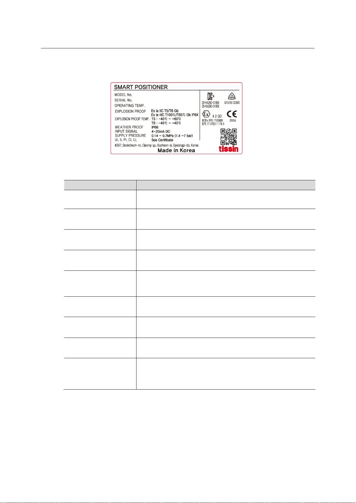
2.5 Label
Item
Description
MODEL No.
Indicate the model number.
SERIAL No.
Indicate the serial number.
EXPLOSION PROOF
Indicate the certified explosion proof grade.
OPERATING TEMP.
Indicate the allowable operating temperature.
EXPLOSION PROOF
TEMP.
Indicate the ambient temperature range for the explosion proof.
This temperature range must be observed when using in
explosion-proof areas.
WEATHER PROOF
Indicate the enclosure grade.
INPUT SIGNAL
Indicates input current signal range.
SUPPLY PRESSURE
Indicate the allowable input supply pressure range.
Ui, Ii, Pi, Ci, Li
Indicate required barrier specification for intrinsically safety circuit
configuration.
Please refer to the certificate for the detailed specifications.

9
Smart valve positioner
TS800 Series
tissin
2.6 Product number
TS800
Model
Standard type
TS800
Remote type
TS820
Acting type
Linear type
L
Rotary type
R
Explosion proof
type
Non-explosion poof
N
Ex ia IIC T5/T6
A
Connection
Conduit entry
Air connection
G(PF)1/2
PT1/4
1
G(PF)1/2
NPT1/4
2
NPT1/2
NPT1/4
3
M20
NPT1/4
4
M20
G1/4
5
Lever type
(Linear )
10~80mm
1
70~150mm
2
Adapter type (70mm)
3
Lever type
(Rotary)
M6 x 34L (Fork lever type)
1
NAMUR
5
Ambient Temp.
-30℃~85℃(Standard type)
S
-40℃~85℃
L
Communication
None
0
Position transmitter (4~20mA DC feedback)
1
HART communication
2
HART and Position transmitter (4~20mA DC feedback)
3
Limit switch
None
0
(For TS800)
Mechanical type (Dry contact NO, NC, COM)
M
Proximity type (P+F NJ1,5-F-N)
P
With Dome cover (Without Limit switch)
D
Cable length
5m
1
(For TS820)
10m
2
User define (Less than 20 meters)
X
10
Smart valve positioner
TS800 Series
tissin
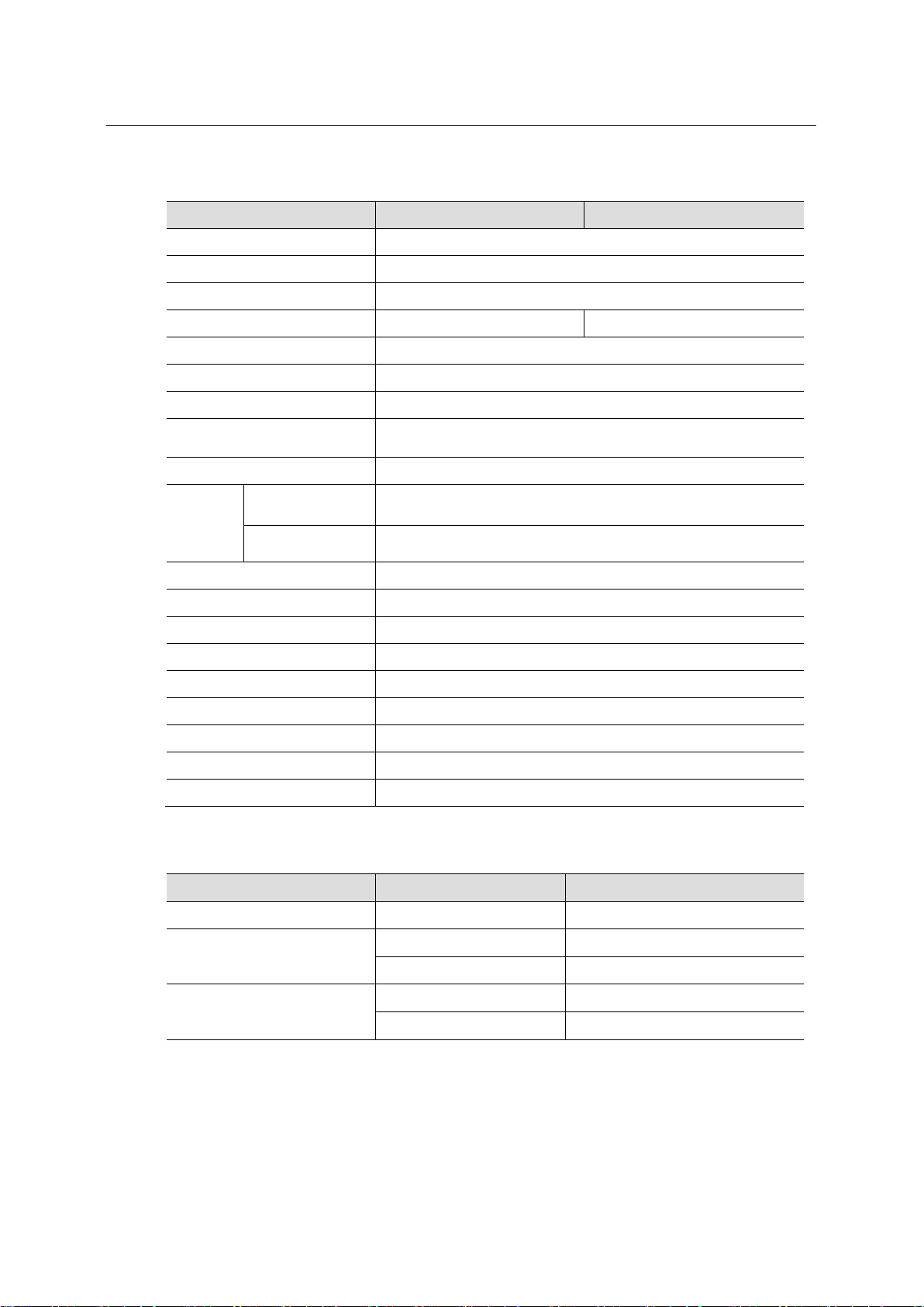
2.7 Specifications
Model
TS800L / TS820L
TS800R / TS820R
Input signal
4~20mA DC
Impedance
500Ω(20mA DC)
Supply pressure
0.14~0.7MPa
Stroke
10~150mm
0~900
Air connection
PT1/4, NPT1/4
Gauge connection
PT1/8, NPT1/8
Conduit
G(PF)1/2, NPT1/2, M20
Explosion proof type
II 2G Ex ia IIC T5/T6 Gb
II 2D Ex ia IIIC T100℃/85℃Db IP6X
Enclosure
IP66 (EN60529)
Ambient
Temp.
Acting Temp.
-30℃∼85℃(Standard type),
-40℃∼85℃(Low temp type)
Explosion proof
Temp.
-40℃~60℃(T5) / -40℃~40℃(T6)
Linearity
±0.5% F.S.
Sensitivity
±0.2% F.S
Hysteresis
±0.5% F.S
Repeatability
±0.3% F.S
Air consumption
Below 2.3LPM (Sup.=0.14MPa)
Required air quality
Class 3 (ISO8573-1)
Flow capacity
Over 100LPM (Sup.=0.14MPa)
Material
Aluminum die cast
Weight
2.2kg
Option specifications
Option
Item
Specification
HART
HART version
HART 7
Position transmitter
Wire connection type
2 Wires
Supply voltage
10~30V DC
Limit switch
Mechanical type
AC125V, 3A, DC30V, 2A
Proximity type
DC8.2V 8.2A
Note: Please contact our sales department for other specifications.
11
Smart valve positioner
TS800 Series
tissin
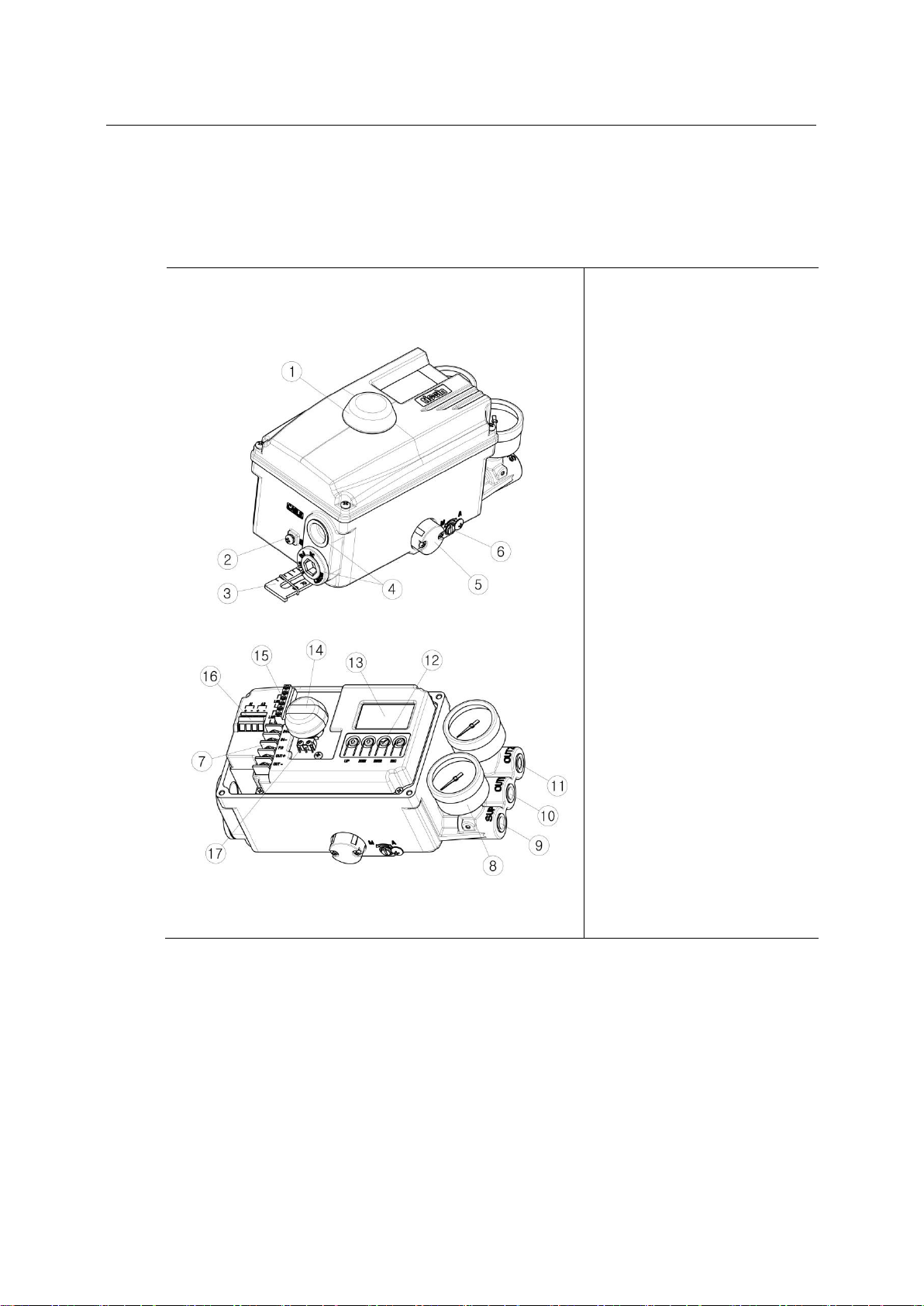
2.8 Structure
2.8.1 External structure
①Dome cover
②External ground
③Feedback lever
④Conduit
⑤Air vent hole cover
⑥Auto/Manual switch
⑦Terminal block
⑧Pressure gauge
⑨Air supply port
⑩OUT1 port
⑪OUT2 port
⑫Button
⑬LCD
⑭Dome indicator
⑮Limit switch
connection terminal
○
16 Alarm connection
terminal
○
17 Limit switch
Note: Only Limit switch type product is equipped with Dome indicator.

12
Smart valve positioner
TS800 Series
tissin
2.8.2 Internal structure
①Pilot valve
②Potentiometer
③Pressure sensor (Option)
④Torque motor
⑤Main PCB
⑥Terminal block
⑦HART communication module (Option)
⑧Position transmitter module(Option)
⑨Buttons
⑩Alarm signal connection terminal
⑪PCB cover
⑫Limit switch connection terminal
⑬Limit switch (Option)
13
Smart valve positioner
TS800 Series
tissin
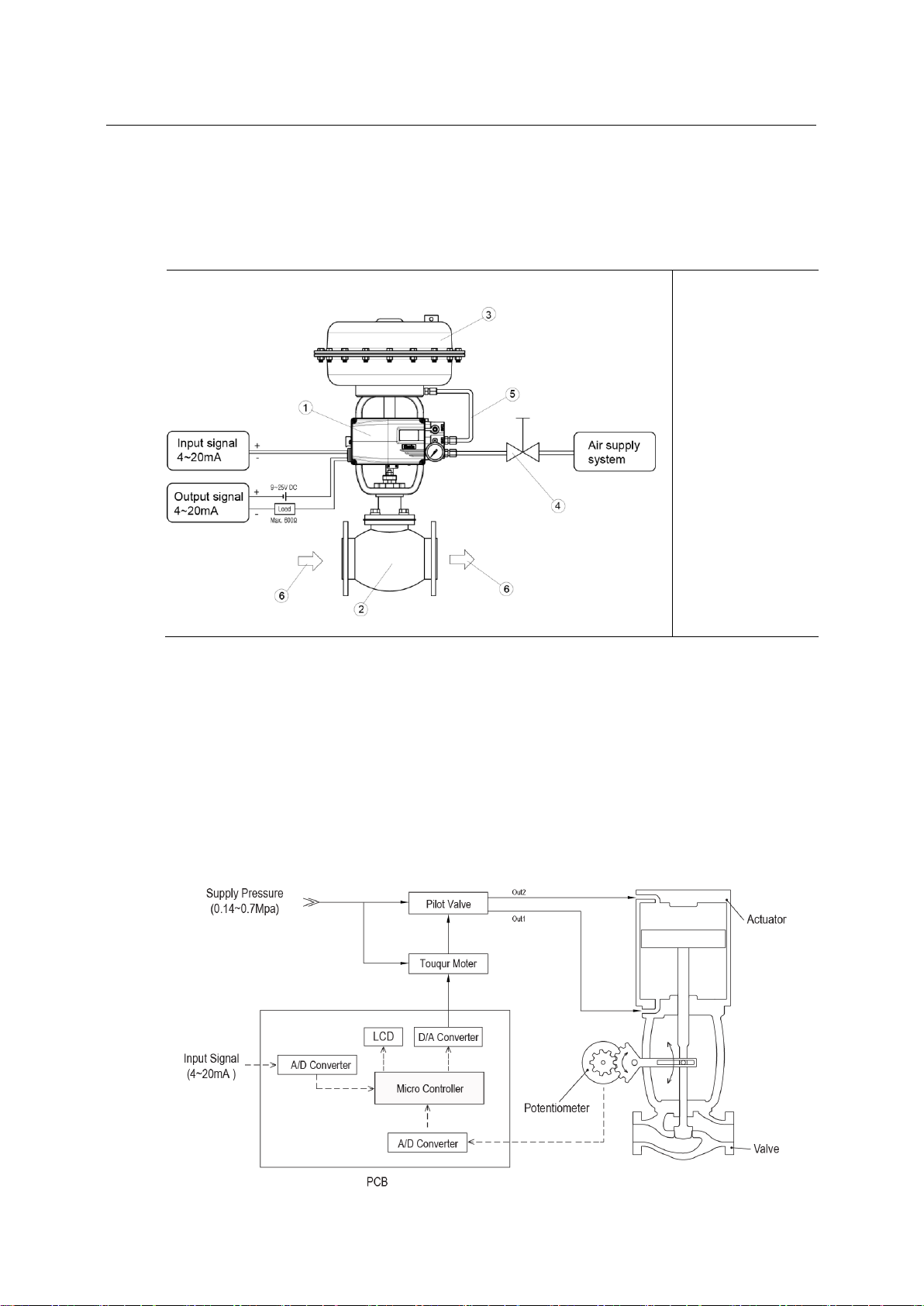
2.9 System configuration
Basically, the control valve system consists of a positioner for controlling the pneumatic
pressure of the actuator, an actuator for controlling the opening of the valve, and a valve for
controlling the flow of the fluid.
①Positioner
(TS800)
②Valve
③Actuator
④Regulator
⑤OUT1 vent line
⑥Fluid
2.10 Operation Principle
TS800 receives 4-20mA input signal of the control room, micro-processor (CPU) compares
input signal with position feedback through potentiometer and sends control signal to I/P
conversion module torque motor, torque motor converts it to a pneumatic signal to controls
pilot valve to controls the opening of the control valve by converting output pressure of OUT1
and OUT2.
14
Smart valve positioner
TS800 Series
tissin
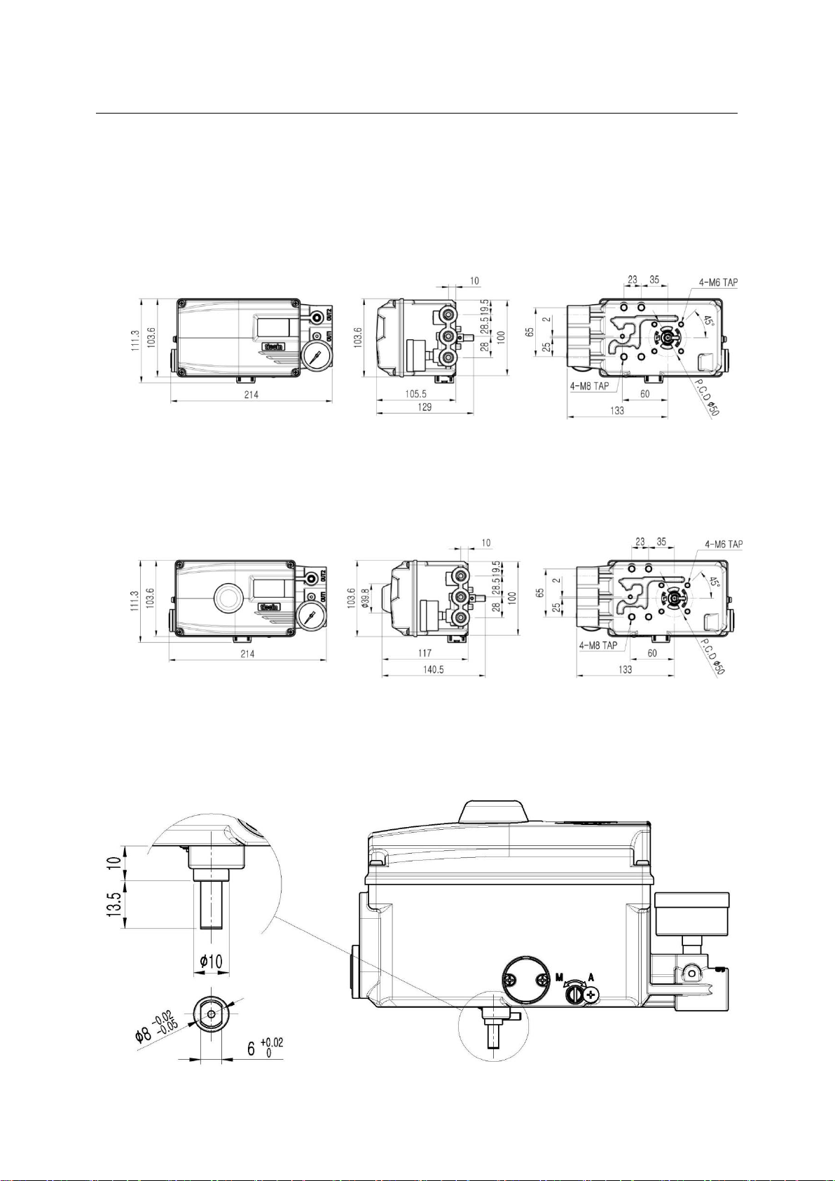
2.11 Approval drawings
2.11.1 TS800 standard type
2.11.2 TS800 with limit switch type
2.11.3 TS800 feedback shaft connection

15
Smart valve positioner
TS800 Series
tissin
3 Installation
3.1 Before installation
WARING
Make sure if TS800 is appropriate to the valve and actuator installation conditions and
the site requirements specifications before installation.
If the installation state is not correct, TS800 control characteristics may be degraded.
3.2 TS800L installation
3.2.1 Notes on installation
When make the mounting bracket and connecting the lever to the stem connection pin, be
sure to observe the following two points.
If failure to observe the followings, it will affect the product performance such as linearity.
NOTICE
①When the valve stroke is 50%, the feedback lever should be horizontal.
②When the valve stroke is 50%, the stem connection pin must be located at the numeric
position marked on the feedback lever that is corresponding to the valve stroke.
①Feedback lever
②Stem connection pin
③Pin fixing spring
④Actuator stem
⑤Valve opening indicator

16
Smart valve positioner
TS800 Series
tissin
3.2.2 Effective rotation angle range of feedback lever
The effective rotation angle of TS800L lever is respectively 30oupward and downward that is
based on horizon.
Follow 3.2.1 notes, effective rotation angle can be maintained to achieve the best
performance.
3.2.3 Lever type and dimension
The numeric positions marked on the feedback lever correspond to the valve stroke, and the
stem connection pin must be connected to the corresponding marked location.
Lever No.
Valve stroke
Dimensions
No.1
10~80mm
No.2
70~150mm
No.3
10~70mm
For the tube less
type actuator
NOTICE
If the rotation angle range is too small during operation, the performance of products
such as linearity may be degradation.
If the rotation angle range is too big during operation, may damage the product or cause
malfunctions.

17
Smart valve positioner
TS800 Series
tissin
3.2.4 Bracket Installation
Refer to the TS800L drawing (refer to 2.11.1) and actuator drawing, please make appropriate
bracket and install the positioner on the actuator.
①Bracket
②Bolt (M8)
③Washer
④Feedback lever
⑤Lever fixing bolt
⑥Main shaft
⑦Shaft fixing pin
3.2.5 Dimension after installation
<Lever No.1 or 2 > <Lever No.3>
①Stem connection pin
②Feedback lever
③Bracket
④Actuator york
⑤Lever adapter

18
Smart valve positioner
TS800 Series
tissin
3.3 TS800R installation
3.3.1 TS800R installation examples
<Fork lever type> <NAMUR type>
3.3.2 TS800R bracket installation components
When shipped from the factory, components No.1~8 are provided as standard.
The brackets support the NAMUR mounting standard (VDI/VDE3835, IEC60534-6-2).
<Fork lever type> <NAMUR type>
①Lower bracket(1)
②Upper bracket(1)
③Nuts(4)
④Screws (M6x4)
⑤Screws (M8x4)
⑥Fork lever(1)
⑦NAMUR adapter (1)
⑧Adapter fixing pin(2)

19
Smart valve positioner
TS800 Series
tissin
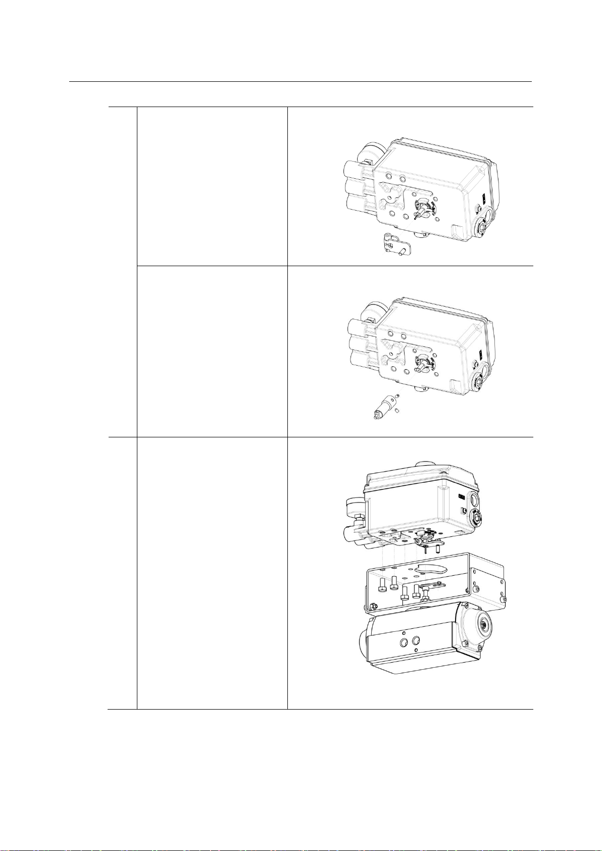
3.3.3 TS800R installation steps
1
Lower bracket installation
Attach the lower bracket to the
actuator and secure it with the
screw.
2
Fork lever installation
Insert the fork lever into
actuator stem and tighten with
the fixing bolt.
Position the start point of the
fork lever according to actuator
stem’s rotation direction.
3
Tighten upper and lower
brackets
Connect the upper bracket to
the lower bracket attached to
the actuator and fasten with
the screw.
Tighten the bolts to the
corresponding holes of 20, 30
and 50 depending on the
actuator stem height.
20
Smart valve positioner
TS800 Series
tissin
4
Shaft lever installation
Fork lever type
Insert the shaft lever into the
main shaft and tighten with the
fixing bolt.
NAMUR type
Insert NAMUR shaft adapter
into the main shaft and fix it
with two fixing pins.
5
Attach the positioner to the
upper bracket and fix it with
screw.
At this time, insert the lever pin
at the bottom of the fork lever
into the hole of the fork lever
attached to the actuator and
then align the center.
Other manuals for TS800 Series
2
This manual suits for next models
4
Table of contents
Other tissin Valve Positioner manuals


Popular Valve Positioner manuals by other brands


Samson
Samson TROVIS SAFE 3730-6 Mounting and operating instructions

Aventics
Aventics AB-1 Service information

Aventics
Aventics R431004026 Service information

Swegon
Swegon SILVER C quick start guide

Avid Technology
Avid Technology EaziCal II operating manual

halstrup-walcher
halstrup-walcher PSD4 Series instruction manual


