Titan Logix TD100 User manual
TD 100
Programming and Configuration Guide
www.titanlogix.com
Page 1
SensorLink is the desktop-based software produced by Titan Logix Corp which is available for free for every Titan
user. Use this guide to:
•Create, and modify a strapping table on any TD Series transmitter
•Set key operational parameters and tank variations
INITIATE PROGRAMMING
Step 1
Connect to the TD100 Transmitter, page 2
•Direct Connection, page 2
•Connection Through the Finch II, page 3
Step 2
Open SensorLink, page 3
STRAPPING TABLE SETUP
Step 3
Input Probe Settings, page 4
Step 4
Input Strapping Table Settings, page 5
Step 5
Input Offset Measurement Settings, page 6
Step 6
Input Alarm Settings, page 7
Step 7
Input Display Settings, page 8
Step 8
(Optional) Input Sump and Riser Settings, page 9
Step 9
Verify the Strapping Table, page 10
Step 10
Save the Strapping Table, page 10
Step 11
Program the transmitter, page 11
IMPORTING THE STRAPPING TABLE
Step 12
Import from .stb Format, page 12
Step 13
Import from .csv Format, page 13
CLONING THE STRAPPING TABLE
Step 14
Copy Existing TD80 Strapping Table, page 14
CONFIGURE (POST-INSTALLATION)
Step 15
Set Rotary Switch, page 16
Step 16
Set Fill Alarm (through Finch II), page 17
Step 17
Set Fall Alarm (through Finch II), page 17
TESTING
Step 18
Initiate Startup, page 18
Step 19
Clear Active Alarms, page 18
TD 100
Programming and Configuration Guide
www.titanlogix.com
Page 2
INITIATE PROGRAMMING
CHECKLIST
Ensure no flammable gases and/or fumes are present before installation or repair.
Turn thevehicle power off before any installation activity.
Ensure the tank is drained of liquid and free of vapors.
Ensure all required tools are available for installation.
Ensure you have the SV Bus Programming Kit.
Ensure SensorLink is installed on your computer.
Ensure you have the tank manufacturer-provided strapping table.
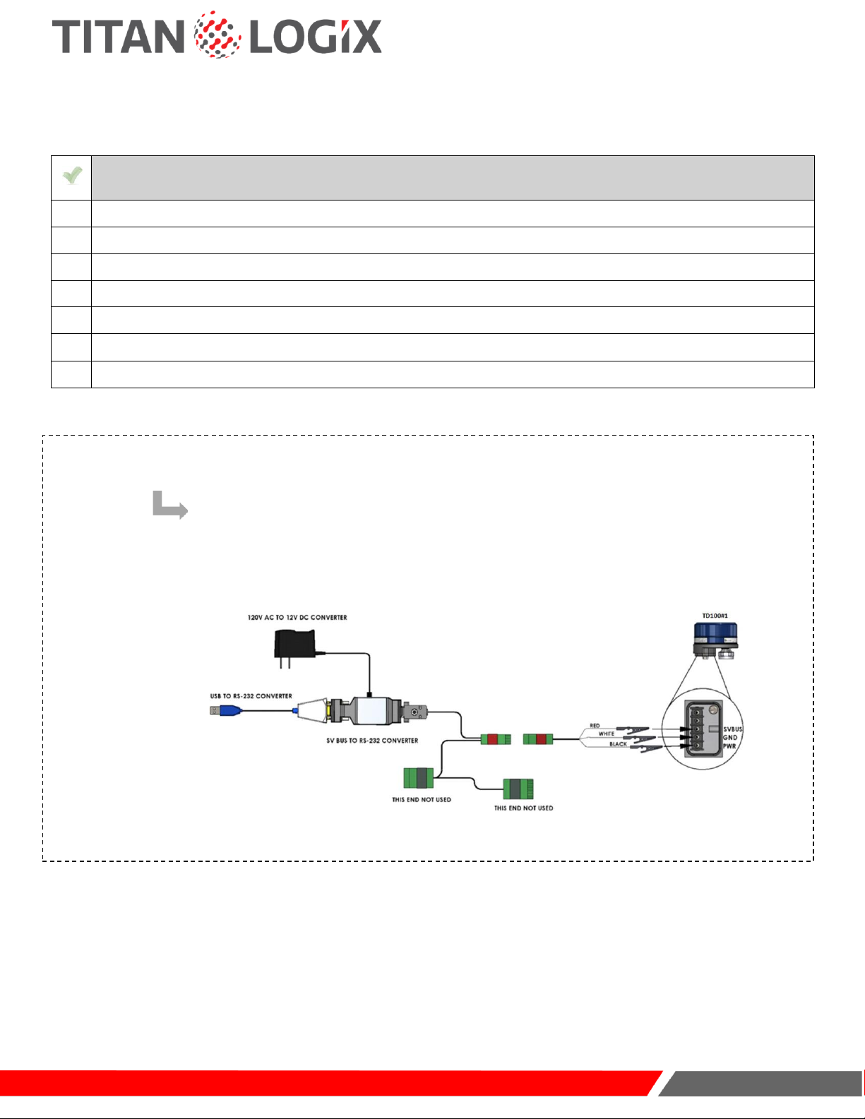
1CONNECT TO THE TD100 TRANSMITTER
START HERE IF MAKING A DIRECT CONNECTION TO THE TRANSMITTER:
Use alligator pins to connect the SV Bus Programming Kit to the transmitter beforeinstalling it on the top of
the tank.
TD 100
Programming and Configuration Guide
www.titanlogix.com
Page 3
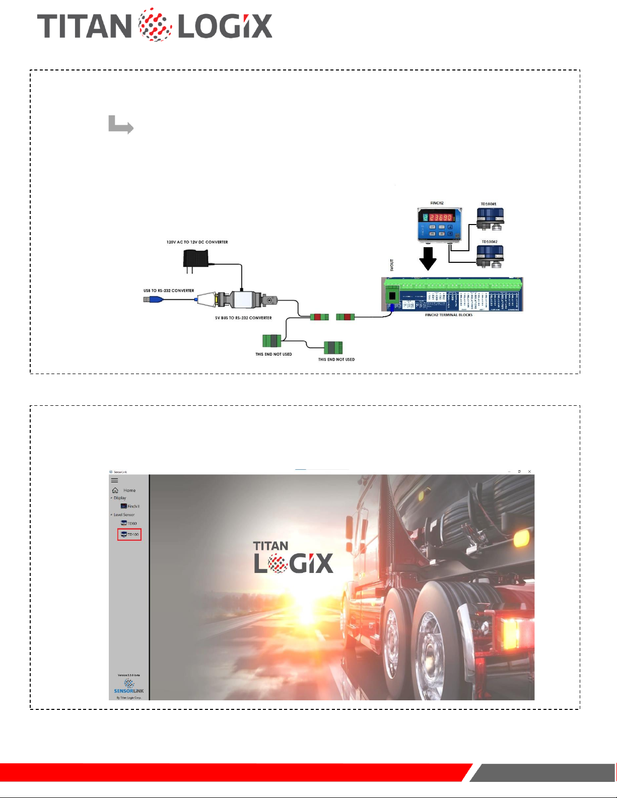
1CONNECT TO THE TD100 TRANSMITTER (CONT.)
START HERE IF MAKING A CONNECTION THROUGH THE FINCH II DISPLAY:
Use the SV Bus Programming Kit adapter to connect to the transmitter via the Finch II Display.
OPEN SENSORLINK
Select the TD100 utility using the SensorLink software:
2
TD 100
Programming and Configuration Guide
www.titanlogix.com
Page 4
STRAPPING TABLE SETUP
CHECKLIST
Ensure the TD100 is connected to a computer using the SV Bus Programming Kit.
Ensure SensorLink is installed and working on your computer.
Ensure the appropriate COM Port Drivers are installed on your computer.
Ensure you have the tank manufacturer-provided strapping table.
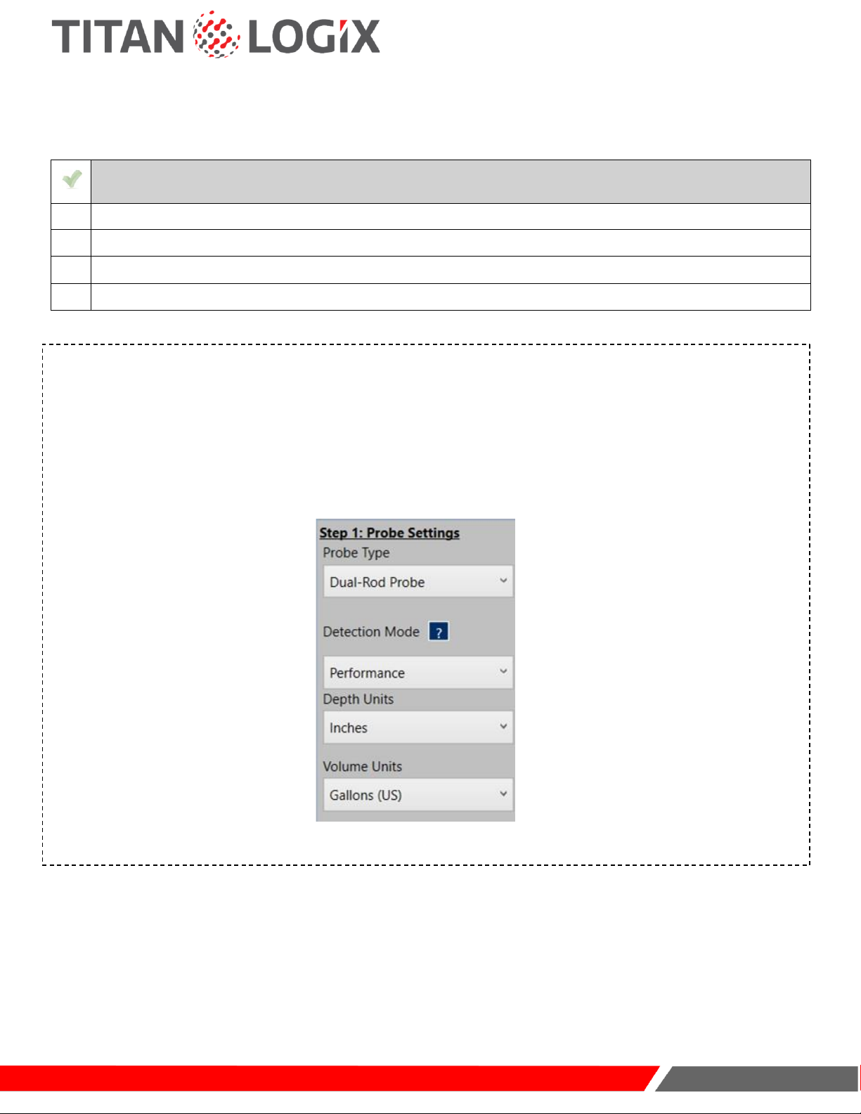
INPUT PROBE SETTINGS (STEP 1)
a. Select the type of probe.
b. Select the detection mode. (Performance mode is recommended for optimal performance. See “Detection
Modes” in SensorLink Help to learn more.)
c. Select the depth unit (to match the manufacturer-provided strapping table).
d. Select the volume unit (to match the manufacturer-provided strapping table).
3
TD 100
Programming and Configuration Guide
www.titanlogix.com
Page 5
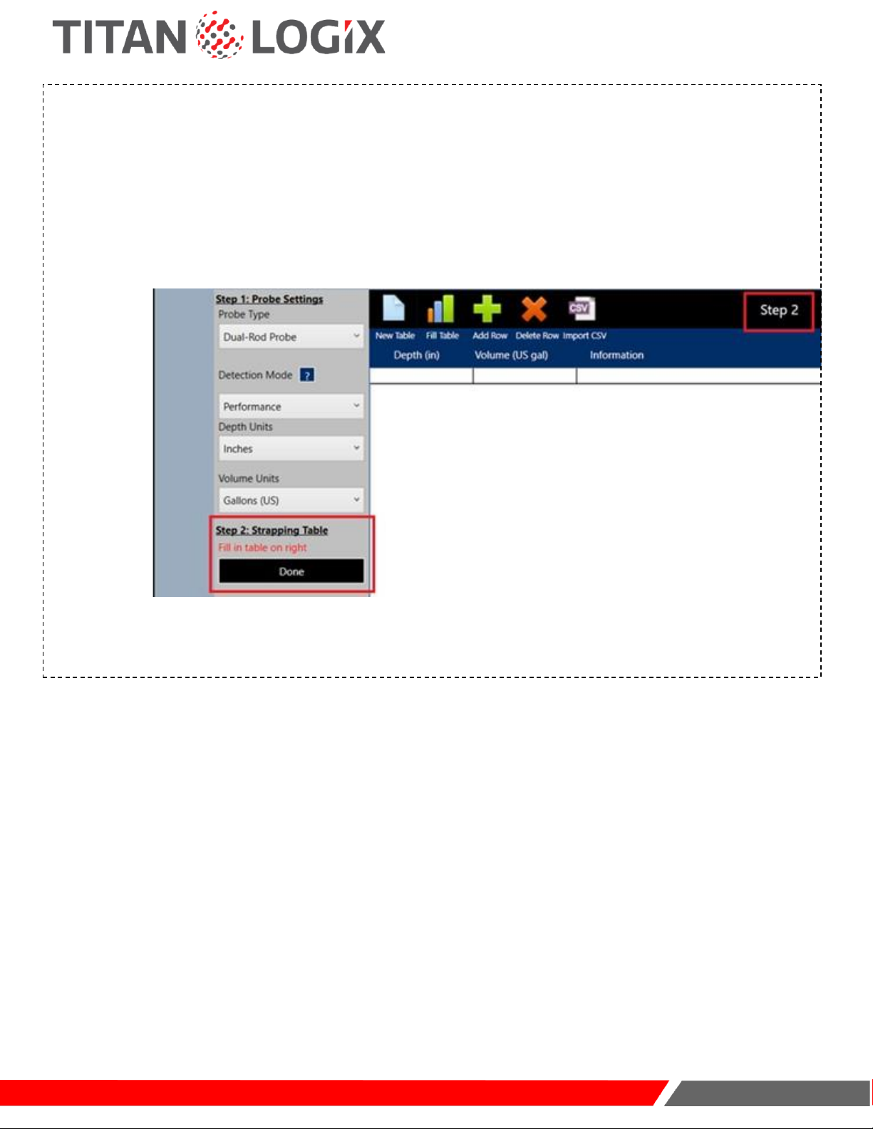
INPUT STRAPPING TABLE SETTINGS (STEP 2)
a. Click on “Add Row” to add rows to the table or start entering the values and press enter after each entry.
b. Manually enter depth and volume values in corresponding columns as given in the manufacturer-provided table.
c. Select the depth unit (to match the manufacturer-provided strapping table).
d. Click on “Done” Step 2. This button toggles between "Done" and "Edit". The user must click the "Done" button
once the editing of the strapping table is complete. Click the "Edit" button any time to make changes to the
strapping table data.
4
TD 100
Programming and Configuration Guide
www.titanlogix.com
Page 6
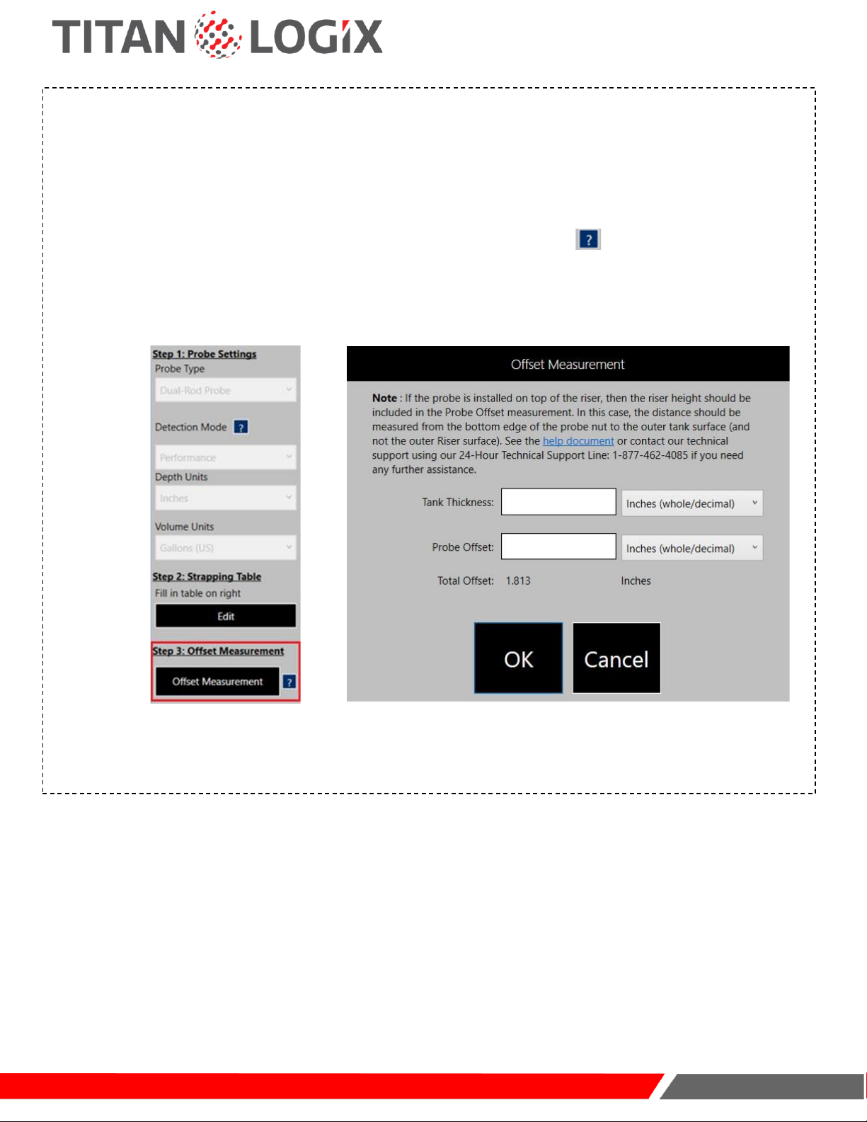
INPUT OFFSET MEASUREMENT SETTINGS (STEP 3)
a. Ensure you have the following data as measured during the mechanical installation process:
•Tank thickness measurement in the appropriate units
•Probe offset measurement in the appropriate units
b. Click on “Offset Measurement” to go to a new dialog box (Please click on to learn more about offset
measurement).
c. In the offset measurement dialog box, manually insert the tank thickness and select the appropriate unit from
the drop-down.
d. Manually insert the probe offset and select the appropriate unit from the drop-down.
5
TD 100
Programming and Configuration Guide
www.titanlogix.com
Page 7
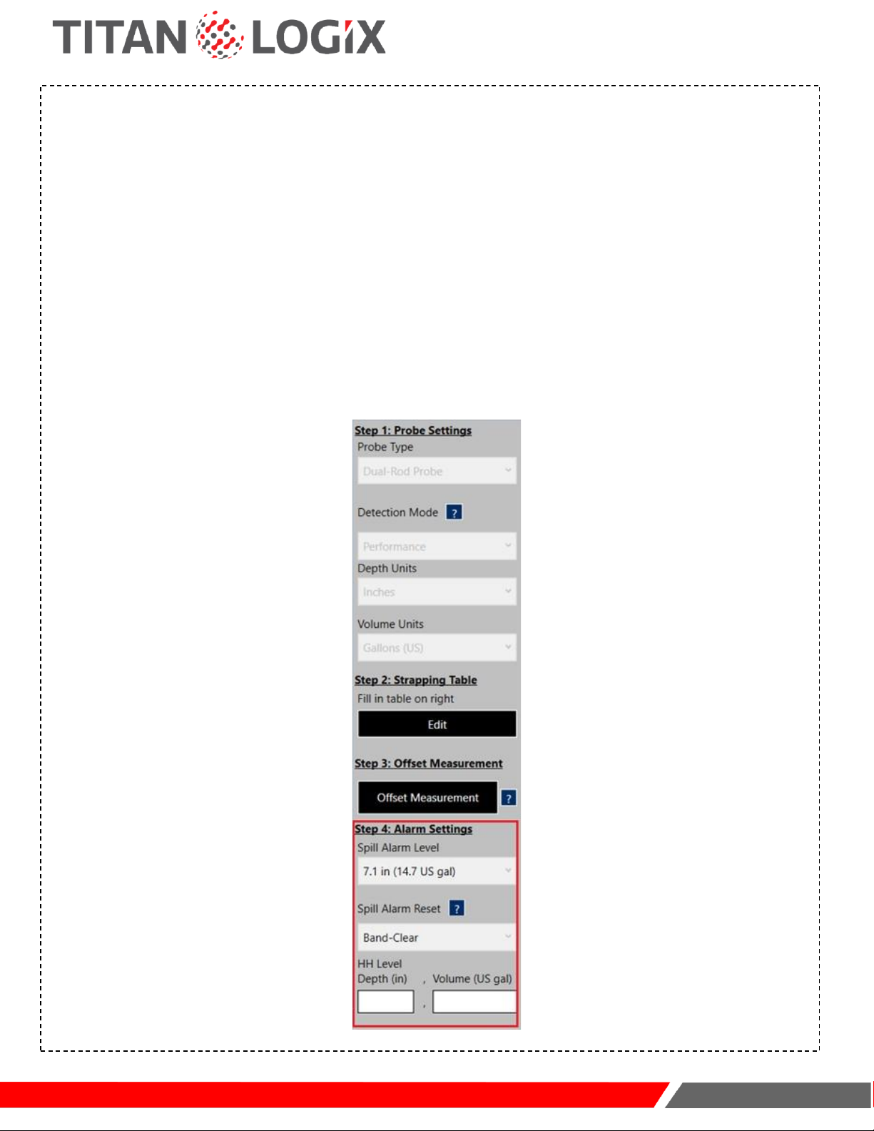
INPUT ALARM SETTINGS (STEP 4)
a. Spill alarm level:
i. For dual-rod probe, no setting is needed by the user. Please see Detection Modes in the SensorLink Help
section to learn more about spill alarm settings.
ii. For the Coax probe, the Spill level can be set from 4" to 17" for Performance Detection Mode and Standard
Detection Mode from the bottom edge of the probe nut. The spill alarm level will only be available for the
selection of a coaxial probe is selected in step one.
b. Select the "Spill Alarm Reset" mode. This setting is dependent on the probe type. For dual-rod probes, only
band-clear mode is available. For the Coax probe, select either Band-clear or Auto-clear mode. For details
about band-clear, please see Spill Reset.
c. Manually enter the HH alarm threshold either in the "HH Level Depth" text box or the "HH Level Volume" text
box. To ensure that the HH is registered by SensorLink please press 'Enter' after entering the HH value. The
HH alarm threshold must be above 2Lo and 2" below the spill level (Spill).
6

TD 100
Programming and Configuration Guide
www.titanlogix.com
Page 8
INPUT DISPLAY SETTINGS (STEP 5)
Select the number of decimal places used for the volume data under the "Precision Setting" drop-down menu.
7
Note: It is recommended to maximize the display resolution or number of decimal places in the volume measurement.
For example, if the maximum volume of the tank is 80 barrels, then the display resolution should be set to 2 decimal
places so that the maximum volume is 80.00. If the maximum volume of the tank is 9000 litres, then the display
resolution should be set to 0 decimal places. A rule of thumb to follow is that if you remove the decimal point from your
maximum volume, it should be as close to but cannot exceed 9999.
TD 100
Programming and Configuration Guide
www.titanlogix.com
Page 9
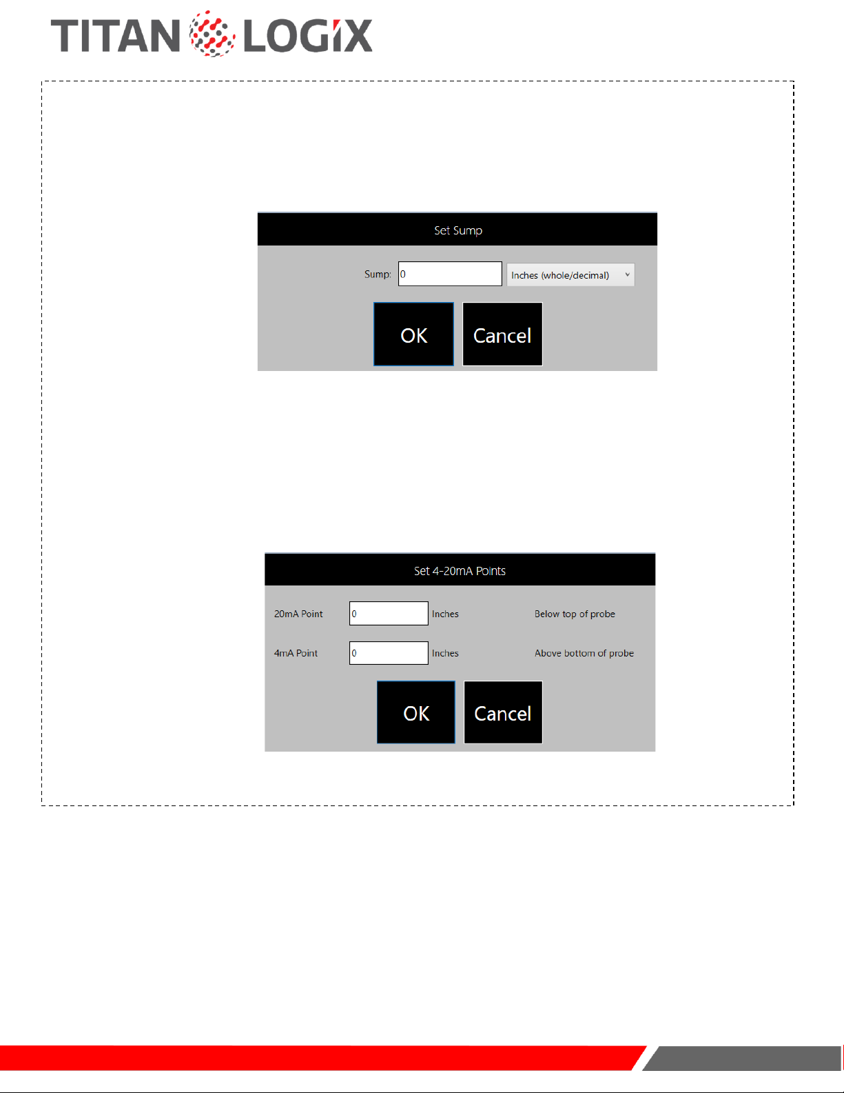
(OPTIONAL) INPUT SUMP SETTINGS
If you have a sump on your tank, go to 'Set Sump' and add the Sump depth value as applicable to the installation.
Clicking the "Set Sump" button will open a new window box in which the user can enter the sump values. The
sump value cannot be less than 0.
If your installation involves the TD100 transmitter that supports a 4-20mA current loop interface, click on "Set 4-
20mA Points" to enter the 4mA and 20mA set points.
While adding these points following restrictions must be observed:
•The 4mA point cannot be less than 0
•The 20mA point cannot be less than 0
•The 4mA point must be set below the 20mA point
8

TD 100
Programming and Configuration Guide
www.titanlogix.com
Page 10
VERIFY THE STRAPPING TABLE
Click on the 'Verify' button from the top ribbon.
If there are no errors, an OK message will be returned, otherwise, any errors will be highlighted for the user to
make necessary corrections.
SAVE THE STRAPPING TABLE
a. Click on the 'File' button to open the menu.
b. Click on the 'Save File' option from the menu.
c. Choose a suitable location for the file.
d. Name the file as you find it suitable (preferably as per your organization's convention).
e. Click 'Save' to save the file (will save to the recommended. stb format for future installations).
9
10

TD 100
Programming and Configuration Guide
www.titanlogix.com
Page 11
PROGRAM
Ensure that the TD100 is connected to the computer using the SV Bus programming kit and all appropriate fields
are filled in SensorLink.
a. Click on the 'Program' button from the top ribbon to open the program dialog box.
b. Select the appropriate COM port of your computer.
c. Power TD100 transmitter off and on using a push button switch on the cable assembly.
d. Immediately click on the 'Program' button to program the TD100 transmitter.
11
TD 100
Programming and Configuration Guide
www.titanlogix.com
Page 12
IMPORTING THE STRAPPING TABLE
CHECKLIST
Ensure the TD100 is connected to a computer using the SV Bus Programming Kit.
Ensure SensorLink is installed and working on your computer.
Ensure the appropriate COM Port Drivers are installed on your computer.
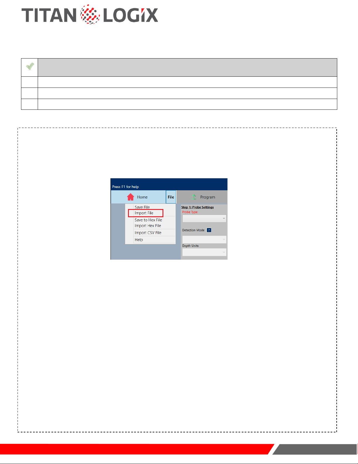
IMPORT FROM. STB FORMAT
a. Open TD100 utility on SensorLink software.
b. Click on the 'File' button to open the menu.
c. Click on the 'Import File' option to select the appropriate strapping table file from your computer drive.
d. Select an appropriate file ((*.stb) format only) from your computer drive.
e. Select 'Open' to copy the table data to SensorLink.
f. If you need to change any installation-specific parameters in steps 1 & 2, click on 'Edit' to make changes and
then click on 'Done' to move to the next step.
g. Click on 'Offset Measurement' from Step 3 to edit offset measurement values.
h. Insert the tank thickness and select the appropriate unit from the drop-down.
i. Insert the probe offset and select the appropriate unit from the drop-down.
j. Click 'OK' to exit the offset measurement dialog box.
k. Change alarm settings and optional settings as per installation requirements.
l. If continuing to program the TD100, follow instruction from SAVE THE STRAPPING TABLE, pg. 10.
12
TD 100
Programming and Configuration Guide
www.titanlogix.com
Page 13
IMPORT FROM .CSV FORMAT
a. Open TD100 utility on Sensorlink software.
b. Click on the 'File' button to open the menu.
c. Click on the 'Import CSV File' option to select the strapping table file.
d. Select an appropriate file (CSV format only) from your computer drive.
e. Select 'Open' to copy the table data to the Sensorlink. The spreadsheet program displaying the CSV file must
be closed before it could be imported into Sensorlink.
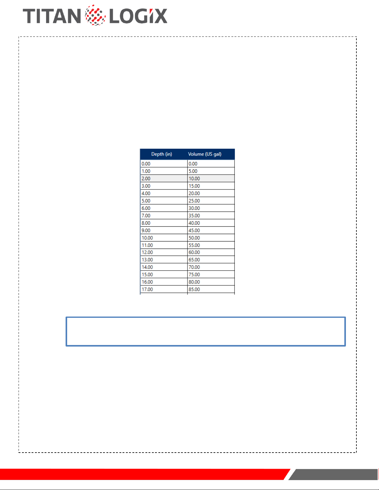
f. Once the file is successfully imported the table should be auto-populated as shown in the image.
g. Continue from SAVETHE STRAPPING TABLE, pg. 10.
13
Note: The import from the CSV file will only auto-populate the table values; all other necessary information to create
the strapping table must be manually entered. Please refer to STRAPPING TABLE SETUP, pg. 4 section to learn more if
you need help in filling out these details.

TD 100
Programming and Configuration Guide
www.titanlogix.com
Page 14
CLONING THE STRAPPING TABLE (TD80 to TD100)
CHECKLIST
Ensure the TD100 is connected to a computer using the SV Bus Programming Kit.
Ensure SensorLink is installed and working on your computer.
Ensure the appropriate COM Port Drivers are installed on your computer.
CLONING EXISTING TD80 STRAPPING TABLE
a. Establish the connection with TD80 either directly or indirectly. Use the procedure found in Connect to the
TD100 Transmitter, pg. 2.
b. Power On the TD80 transmitter.
c. Open the TD80 Utility on SensorLink.
d. Click on "Read' on the top ribbon to copy the strapping table data from the TD80.
e. Manually select the Probe Type, Depth Units, Volume Units, and Display Precision (Decimal Point).
f. Click on the 'File' button to open the menu.
g. Click on the 'Save File' option from the menu.
14

TD 100
Programming and Configuration Guide
www.titanlogix.com
Page 15
14
CLONING EXISTING TD80 STRAPPING TABLE (CONT.)
h.Choose a suitable location for the file.
i.Name the file.
j.Click 'Save' to save the strapping table to .stb file format.
k.Click on TD100 from the sidebar to go to the TD100 utility.
l.Once in the TD100 utility, continue from IMPORT FROM.STBFORMAT, pg. 12.
NOTE: When importing a TD80 table into the TD100, the Standard Detection Mode is automatically selected, and a
total offset of 1.813" is automatically added to account for the difference in probe alignment between the TD80 and
the TD100.

TD 100
Programming and Configuration Guide
www.titanlogix.com
Page 16
CONFIGURE (POST-INSTALLATION)
CHECKLIST
Ensure no flammable gases and/or fumes are present before installation or repair.
Turn thevehicle power off before any installation activity.
Ensure the tank is drained of liquid and free of vapors.
Ensure all required tools are available for installation.
Ensure you have the SV Bus Programming Kit.
Ensure SensorLink is installed on your computer.
Ensure you have the tank manufacturer-provided strapping table.
SET ROTARY SWITCH
Open the Finch II enclosure and set the rotary switches. Ensure the number in the DECIMAL rotary switch setting
matches the Display Resolution (step 5 –Display Settings) unit number - set to 1 for 1 decimal place and 2 for 2
decimal places etc.
15

TD 100
Programming and Configuration Guide
www.titanlogix.com
Page 17
SET FILL ALARM (THROUGH FINCH II)
a. Use the 'COMP SELECT' button on Finch II to select the appropriate compartment.
b. Press the 'Up' arrow for 3 seconds and release it to enter the Set Fill alarm mode.
c. The display will flash "Fill" 3 times followed by the current fill alarm level.
d. Fill alarm level can be adjusted by pressing either the up or down arrows.
e. After the 'Fill' alarm is adjusted, the FILL level will be saved automatically after 2 seconds of inactivity.
SET FALL ALARM (THROUGH FINCH II)
a. Use the 'COMP SELECT' button on Finch II to select the appropriate compartment.
b. Press the 'Down' arrow for 3 seconds and release it to enter the Set Fall alarm mode.
c. The display will flash "Fall" 3 times followed by the current fall alarm level.
d. Fall alarm level can be adjusted by pressing either the up or down arrows.
e. After the 'Fall' alarm is adjusted, the FALL level will be saved automatically after 2 seconds of inactivity.
16
17

TD 100
Programming and Configuration Guide
www.titanlogix.com
Page 18
TESTING
CHECKLIST
Visually inspect all mechanical installations.
Visually inspect all electrical installations.
Ensure all required tools are available for testing.
INITIATE START-UP
Apply power to theTD100 system.
Finch II display will show and test:
•current firmware revision number
•five digits and compartment number(s) showing the values from 0 to 9 and A to F
•HORN relay (pulsed for 1 second)
The Finch II display may show one of the following:
•“2 LO” if the tank is empty or contains liquid and the depth is less than 4.5”
•Tank volume if the tank contains liquid and the depth is greater than 4.5”
•“E xxxx” indicating an error code (where x is a number)
•"Display dash lines (" "), suggesting there is no communication between the TD100 and the Finch II
CLEAR ACTIVE ALARMS
Press the “ACK” button to clear any active alarms.
18
19
NOTE: All alarms (except for Spill and Fail) can be cleared using the “ACK”button on the
display.
Other manuals for TD100
2
Table of contents
Popular Transmitter manuals by other brands

jotron
jotron TA-7650C Maintenance and Repair Manual

MuxLab
MuxLab 500058-WP-UK Quick installation guide

Vega
Vega VEGABAR 82 operating instructions

Siemens
Siemens miniTek user guide

BWI Eagle
BWI Eagle AIR-EAGLE SR PLUS 36-1400-4B-DC Product information bulletin

RHEONIK
RHEONIK RHE28 Installation & start?up guide


