TJERNLUND UCRT User manual

Copyright © 2011, Tjernlund Products, Inc. All rights reserved P/N 8504162
OWNER INSTRUCTIONS, DO NOT DESTROY
Recognize this symbol as an indication of important Safety Information!
THESE INSTRUCTIONS ARE INTENDED AS AN AID TO QUALIFIED, LICENSED
SERVICE PERSONNEL FOR PROPER INSTALLATION, ADJUSTMENT AND
OPERATION OF THIS PRODUCT. READ THESE INSTRUCTIONS THOROUGHLY
BEFORE ATTEMPTING INSTALLATION OR OPERATION. FAILURE TO FOLLOW
THESE INSTRUCTIONS MAY RESULT IN IMPROPER INSTALLATION, ADJUST-
MENT, SERVICE OR MAINTENANCE POSSIBLY RESULTING IN FIRE, ELECTRI-
CAL SHOCK, CARBON MONOXIDE POISONING, EXPLOSION, PERSONAL
INJURY OR PROPERTY DAMAGE.
!
DO NOT DESTROY. PLEASE READ CAREFULLY AND
KEEP IN A SAFE PLACE FOR FUTURE REFERENCE.
MODEL UCRT (UC1 with speed control)
INSTALLATION INSTRUCTIONS
REV. A 5/11
TJERNLUND PRODUCTS, INC.
1601 Ninth Street • White Bear Lake, MN 55110-6794
PHONE (800) 255-4208 • (651) 426-2993 • FAX (651) 426-9547
Visit our web site • www.tjernlund.com
UC1 VERSION
X.06
THE UCRT CONTROL IS ONLY SUITABLE FOR USE WITH
TJERNLUND RT SERIES ROOFTOP DRAFT INDUCERS

1
TABLE OF CONTENTS
Page (s)
Description and General Information...............................................................................................................................1
Installation Restrictions and Cautions ........................................................................................................................1, 2
UC1 Universal Control Board Features ..........................................................................................................................2
LED Status / Fault Indicators and Fault Retrieval from Memory .................................................................................2, 3
Pre / Post-Purge & Pre-Cycle Prover Status Check Settings......................................................................................3, 4
UCRT Installation ...........................................................................................................................................................4
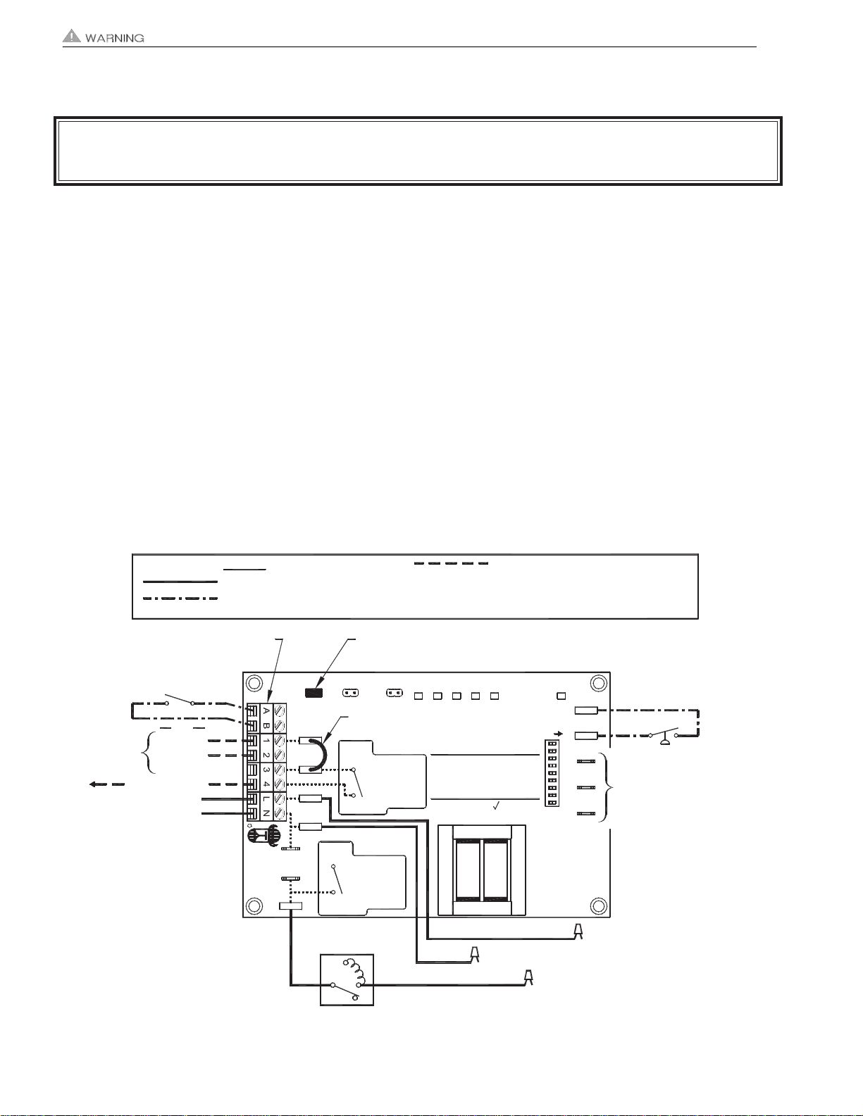
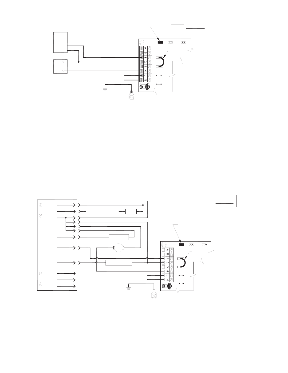
Electrical Wiring
Specifications, Warnings, Sequence of Operation & Internal Schematic .....................................................4, 5
Inducer Ground, Motor and Prover Safety Circuit Connections .......................................................................6
Multiple and Millivolt Appliance interlocks ........................................................................................................6
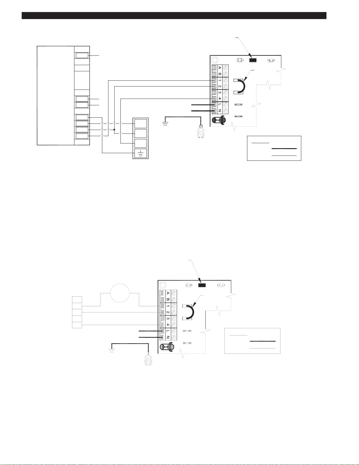
Wiring to Gas Fired Appliance ......................................................................................................................7-9
Wiring to Oil Fired Equipment .....................................................................................................................9-11
PSA-1 Fan Proving Switch Adjustment ........................................................................................................................12
UC1 Operational Check ................................................................................................................................................13
Troubleshooting Electrical Problems........................................................................................................................13-15
Warranty & Replacement Parts.....................................................................................................................................15
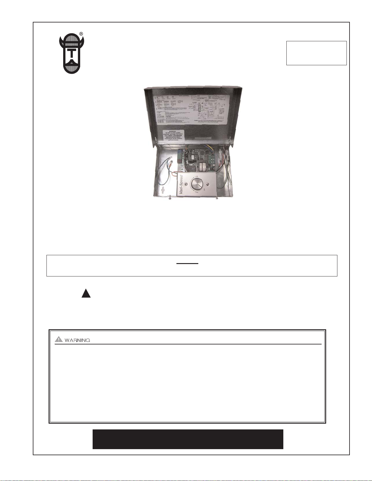
DESCRIPTION
The UCRT combines Tjernlund’s UC1 burner interlock control with an Inducer speed control. It is designed for use ONLY with
Tjernlund RT-Series Rooftop Inducers. Follow these instructions through page 11 for information, options and wiring for the UC1.
Follow PSA-1 proving switch adjustment procedures on page 12 or within the RT-Series Rooftop Inducer Installation Instructions.
The UC1 interlock control can be interlocked with virtually any burner control circuit. Features include: adjustable pre & post
purge, LED status / diagnostic indicators, 10 second prover switch delay to avoid burner start up and wind induced short cycling.
Interlocks with any 24-115 VAC burner control circuit and also includes “dry” contact actuation option. After each burner cycle the
UC1 will continue to operate in post-purge mode to allow the Inducer to purge the heater and vent of residual flue gases. A factory
post-purge time is set at 2 minutes and is adjustable up to 16 minutes, see “Pre / Post Purge and Prover Status Check Dip Switch
Settings” on page 3.
GENERAL INFORMATION
Each UC1 is electrically factory line tested before shipment.
After opening carton, inspect thoroughly for hidden damage. If any damage is found notify freight carrier and your distributor
immediately and file a concealed damage claim.
INSTALLATION RESTRICTIONS
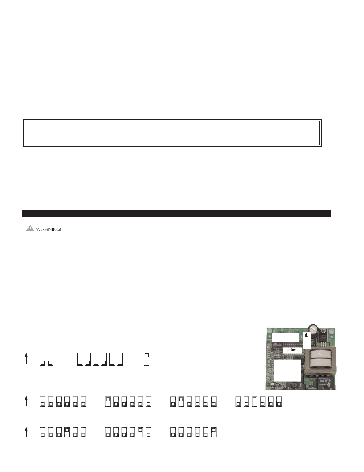
1. The Pre-Cycle Prover Status Check is deactivated from the factory on the UCRT. Natural chimney draft may be sufficient to
close the PSA-1 Fan Prover contacts prior to a call for heat which may cause nuisance lockouts. The Pre-Cycle Prover Status
dip switch #9 should be up or “ON” so that it is deactivated. See page 4 for details.
2. An Inducer post-purge on the UC1 has been factory set at 2 minutes. Confirm that dip switch #5 is in the up or "on" position.
Oil fired equipment requires that the post-purge be long enough to eliminate post cycle nozzle drip odor. A longer post-purge
may be necessary for longer vent runs or high heat retention, refractory lined combustion chambers. A shorter post-purge may be
desired for gas installations. See “Pre / Post Purge Dip Switch Settings” on page 3 for details.
3. The UCRT is intended for indoor installation only. Do not mount the UCRT on a heat source that exceeds 140oF (60oC).
Examples of improper mounting surfaces include vent pipe, top of heater casing or any place where radiant or convective heat
would cause the junction box temperature to exceed 140oF (60oC).
CAUTIONS
The UC1 must be installed by a qualified installer (an individual properly licensed and/or trained) in accordance with all local
codes or, in their absence, in accordance with the appropriate National Fire Protection Association #31, #54, #211 and the
National Electrical Code.
Failure to install, maintain and/or operate the UC1 in accordance with manufacturer's instructions may result in conditions
which can produce bodily injury and property damage.
1. The installer must verify that the BTU/hr. input of the appliance does not exceed the recommended input of the any Inducer
being controlled by the UC1. Refer to the Rooftop Inducer installation instructions for capacities.
2. Disconnect power supply from the UC1 and heating equipment when making wiring connections and servicing the UC1.
Failure to do so may result in personal injury and/or equipment damage. LED #6 (RED) should be off with power removed.

2
3. All installation restrictions and instructions in the Inducer installation instructions must be adhered to when using the UC1.
4. Make certain power source is adequate for the UC1 and Venter requirements. Do not add equipment to a circuit when the total
electrical load is unknown.
UC1 UNIVERSAL CONTROL BOARD FEATURES
# 1. Power supplied by board. Do not supply power to this area or control damage may result.
# 2. Do not supply power to the appliance interlock block with the call selector in the “DRY” position.
Control damage may result if power is supplied.
# 3. Circuit protection must be provided by the installer. 16 Amps is the maximum current allowed for this device at terminal L.
A 15 Amp circuit breaker is recommended.VETI
IUC1 LED STATUS & FAULT INDICATORS
LED INDICATOR LIGHTS
LED #1 (Amber) Appliance call for heat.
LED #2 (Blue) Safety circuit through P1 & P2 (Inducer Fan Prover and/or Limit). Indicates Inducer prover is closed
during run cycle. Burner circuit is energized with Interlock Relay contact closure from terminal 3 to 4.
LED #3 (Green) Power switched to Inducer motor from L to MTR & M.
LED #4 (Red) Status / Fault indicator.
LED #5 (Red) Used as a status indicator.
LED #6 (Red) 115 VAC power supplied to board.
APPLIANCE CALL
VOLTAGE SELECTION
Place RED voltage jumper in
proper location based on
appliance call interlock volt-
age. SEE WARNING # 2.
IMPORTANT
LED 1 (AMBER)
LED 2 (BLUE)
LED 3 (GREEN)
LED 4 (RED)
LED 5 (RED)
LED 6 (RED) POWER LED
DRY
24 V
115 V
APPLIANCE
INTERLOCK
RELAY
INDUCER
MOTOR
RELAY
A B 1 2 3 4 L N
J1 J2 XL XN
P1 P2 C GND F
(1 9)
N M MTR
J1- J2 CALL
JUMPER
Used when the call signal is
used as the “proven” return
signal to the appliance. See
wiring section for details.
L / N - 115 VAC POWER
SUPPLY BLOCK
115 VAC / 50-60 Hz
Circuit protection provided by installer.
SEE WARNING # 3.
MTR & M / N LOAD TERMINALS
FROM INDUCER MOTOR RELAY
Used to drive Inducer Motor.
1 HP MAX LOAD across terminals MTR & M / N.
XL / XN AUXILIARY DEVICE
POWER TERMINALS
115 VAC - Maximum of 0.15 Amps.
Only connect to Tjernlund auxiliary devices.
SEE WARNING # 1.
APPLIANCE INTERLOCK
RELAY
1 HP MAX LOAD across
terminals 3 & 4.
P1 - P2 SAFETY CIRCUIT
TERMINALS
1 mA @ 5VDC.
SEE WARNING # 1.
C, GND, F AUXILIARY DEVICE
COMMUNICATION TERMINALS
2 mA @ 5VDC. For Tjernlund MAC1E or
MAC4E auxiliary devices. SEE WARNING # 1.
DIP SWITCH SETTINGS
Pre-Purge (1-2)
Post-Purge (3-8)
Prover status check (9)
See “Pre / Post Purge &
Prover Status Check Dip
Switch Settings”.
LED STATUS LIGHTS
See “LED Status & Fault
Indicator Section” for details.
APPLIANCE INTERLOCK
TERMINAL BLOCK (A-B, 1-4)
A - B - Dry Contact call. 3 mA @ 5VDC.
SEE WARNING # 1.
1- 24 or 115 VAC intercepted call.
IMPORTANT: RED voltage jumper must
match intercepted call voltage.
2- 24V common or 115V Neutral.
3- Common terminal to appliance relay con-
tacts. IMPORTANT: J1-J2 jumper routes
call voltage at terminal 1 to 3. Remove
J1-J2 jumper if a different voltage source is
provided to terminal 3.
4- Normally open terminal of appliance relay.
Will be energized from terminal 3 if safety
circuit is “proven”.
INDUCER MOTOR RELAY
1 HP MAX LOAD from
terminals L to MTR & M.

LED STATUS INDICATORS
LED #4 & #5 (Red) Flashing Alternately = Inducer in Pre-purge. (Pre-Purge options 0, 5, 20, 35 seconds)
LED #4 & #5 (Red) Flashing in Unison = Inducer in Post-Purge. (Post-Purge options 0, 30 seconds or 1, 2, 4, 8, 16 minutes)
LED #4 Flashes Continuously* = Fan Prover opened for more than 10 seconds during burner cycle.
(Inducer will run for 10 minutes, attempting to close Fan Prover)
LLED #5 (Red) Flashing Intermittently = With no call for heat, flashes 3 seconds on / 3 seconds off if microcontroller is working properly.
LED FAULT INDICATORS
Fault conditions are indicated by counting the number of times LED #4 (Red) flashes.
LED #4 Flashes 2 Times Fan Prover was in electrically closed position prior to Inducer operation.
LED #4 Flashes 3 Times* Fan Prover does not close within 60 seconds after call for heat.
LED #4 Flashes 4 Times* Fan Prover opened during cycle and did not close within 10 minutes of Inducer operation.
LED #4 Flashes 5 Times* Fan Prover opened for more than 10 seconds during burner cycle but closed within 10 minutes.
* Investigate cause of Fan Prover short cycling such as; firing burner at capacities or temperatures exceeding Inducer limits, excessive vent pipe
runs, high winds, plugged / kinked Fan Prover sensing tube. PSA-1 Fan Prover may be faulty or setpoint may be too high and need adjustment.
CHECKING MEMORY FOR LAST FAULT CODE
IMPORTANT: Prior to accessing the fault code memory, note the settings of the dip switches so that they can be returned to their
original Pre / Post-Purge positions. When power is supplied to the UC1 use caution when moving dip switches.
The last fault code can be retrieved at any time by setting all dip switches 1-8 to the up, or “on” position. The last fault code, or
lack there of, will be indicated by counting the number of times LED 4 flashes. By moving any of the dip switches back to their
original position, the fault code will be cleared. NOTE: The UC1 board must have its 115 VAC power supply present when any of
the (1-8) dip switches are moved back to their original position for the fault code to clear.
PRE / POST PURGE AND PROVER STATUS CHECK DIP SWITCH SETTINGS
Remove power to UC1 and heating equipment when installing, servicing or changing dip switch settings. Failure to do so may result in
personal injury and/or equipment damage. LED #6 (RED) should not be on if 115 VAC supply power is removed from the control.
Pre-purge
Used for longer vent runs to get draft fully established throughout the vent system prior to burner ignition. Also beneficial for nega-
tive pressure prone environments. IMPORTANT: Nuisance equipment lockouts may occur if Inducer pre-purge is running in con-
junction with and is longer than any equipment timing circuit. Pre-purge settings must be shorter than burner control lockout time
unless wired prior to burner control timing circuit (i.e. aquastat / thermostat).
Post-purge
An Inducer post-purge has been factory set at 2 minutes. Confirm that dip switch #5 is in the up or "on" position. Oil fired equip-
ment requires that the post-purge be long enough to eliminate post cycle nozzle drip odor. A longer post-purge may be necessary
for longer vent runs or high heat retention, refractory lined combustion chambers. A shorter post-purge may be desired for gas installa-
tions.
IMPORTANT: Fault codes will automatically be displayed after a fault condition occurs. If the call for heat interlock signal
or 115 VAC power is removed, the UC1 board will reset and the fault will be stored in memory instead of displayed. Any
new fault will replace any previous fault.
3
Pre-Purge Post-Purge
Pre-Cycle
Prover Status
Check Deactivated
DIP SWITCH NUMBERING
1
ON 2345678 9
POST-PURGE SETTINGS (SEE “POST-PURGE” ABOVE PRIOR TO SETTING)
4348657 35678 345678 3 75468
4348657 35678 345678
4 Minutes 8 Minutes 16 Minutes
1 Minute0 Seconds 30 Seconds 2 Minutes
ON
ON
1 9
LED 1 AMBER
LED 2 BLUE
LED 3 GREEN
LED 4 RED
LED 5 RED
LED 6 RED
POWER LED
ON

4
UCRT INSTALLATION
Do not mount the UCRT junction box on a heat source that exceeds
140oF (60oC). Examples of improper mounting surfaces include vent
pipe, top of heater casing or any place where radiant or convective heat
would cause the junction box temperature to exceed 140oF. The UCRT
is intended for indoor installation only.
Using the key hole slots on the back of the UCRT junction box as a
template, mark 4 holes on the mounting surface, drill pilot holes if nec-
essary, and secure junction box using provided screws.
The Rooftop Inducer includes a 4’ whip and weatherproof junction box.
The PSA-1 must be mounted with the diaphragm in a vertical position.
See Rooftop Inducer instructions for complete installation details.
ELECTRICAL WIRING
FIGURE 8050021
UC1
RT SERIES
UC1 or UCRT
PSA-1
2 WIRE +
GROUND
INSTALLER-SUPPLIED
BURNER INTERLOCK
INSTALLER-SUPPLIED
115 VAC CONNECTION
CONNECTION
T
O
R
O
O
F
T
O
P
U
N
I
T
3
W
I
R
E
+
G
R
O
U
N
D
POWER
REQUIREMENTS
EXTERNAL
POWER SWITCHING
CAPACITY
J1 / J2
JUMPER
SAFETY
CIRCUIT
ADD VENTER MOTOR
LOAD PLUS 1/2 AMP
FOR UC1 LOAD
EXTERNAL
CALL TRIGGER
METHODS
J1 / J2
P1 / P2
L / N
3 TO 4
T-BLOCK
T-BLOCK
(RELAY K1)
XL / XN
UC1 CONTROL
M & MTR
(RELAY K2)
T-BLOCK
A / B
24V
1 / 2
115V
1 / 2
OR
OR
USED TO JUMP CALL HOT (24 VAC) OR CALL LINE (115 VAC) FROM TERMINAL 1 TO TERMINAL 3.
CONNECTED TO FAN PROVER.
1 mA @ 5 VDC. DO NOT SUPPLY POWER HERE.
REMOVE J1-J2 JUMPER IF A DIFFERENT VOLTAGE SOURCE IS PROVIDED TO TERMINAL 3.
120 VAC ±10 %, 50/60 Hz
MOTOR - 1 H.P. MAX. @ 120 VAC, 50/60 Hz
USER-PROVIDED 24 VAC AT TERMINALS 1 & 2. 1 = CALL HOT, 2 = COMMON. CONTROL
REQUIRES 5 mA @ 24 VAC TO TRIGGER. MOVE RED VOLTAGE JUMPER TO "24V" LOCATION.
3 mA @ 5 VDC. MOVE RED VOLTAGE JUMPER TO "DRY" LOCATION. DO NOT SUPPLY POWER.
USER-PROVIDED CONTACT CLOSURE FROM A TO B. SIZE CONTACT CLOSURE TO HANDLE
GENERAL PURPOSE - 15A @ 120 VAC, 50/60 Hz
DURING OPERATION THE CONTROL USES 50 mA MAX @ 120 VAC
MOTOR - 1 H.P. MAX. @ 120 VAC, 50/60 Hz
150 mA MAX @ 120 VAC, 50/60 Hz
CAN ONLY BE CONNECTED TO TJERNLUND-SPECIFIED AUXILIARY DEVICE
CIRCUIT PROTECTION PROVIDED BY INSTALLER
GENERAL PURPOSE - 15A @ 120 VAC, 50/60 Hz
RESISTIVE - 10A @ 28 VDC PILOT DUTY - 470 VA
USER-PROVIDED 115 VAC AT TERMINALS 1 & 2. 1 = CALL LINE, 2 = NEUTRAL. CONTROL
REQUIRES 1 mA @ 115 VAC TO TRIGGER. MOVE RED VOLTAGE JUMPER TO "115V" LOCATION.
D/N 9183006H
ON
PRE-PURGE SETTINGS (SEE “PRE-PURGE” ON PAGE 3 PRIOR TO SETTING)
12 12 12 12
0 Seconds 5 Seconds 20 Seconds 35 Seconds
P1 & P2 PRE-CYCLE FAN PROVER STATUS CHECK
Pre-Cycle
Prover Status
Check Deactivated 9
The Pre-Cycle Prover Status Check is deactivated from the factory on the UCRT. Natural chimney
draft may be sufficient to close the PSA-1 Fan Prover contacts prior to a call for heat which may
cause nuisance lockouts. The Pre-Cycle Prover Status dip switch #9 should be up or “ON” so that
it is deactivated.
ELECTRICAL SPECIFICATIONS
TYPICAL UCRT, PSA-1 FAN PROVER
& ROOFTOP INDUCER INSTALLATION
UCRT
ROOFTOP INDUCER
INCLUDES 4’ WHIP
AND WEATHER-
PROOF BOX
SPEED CONTROL RED LEAD
TO INDUCER 6 AMPS MAXIMUM @ 120 VAC 50/60 HZ.

All wiring from the UC1 to the appliance must be appropriate Class 1 wiring as follows: installed in rigid metal conduit, intermediate
metal conduit, rigid non-metallic conduit, electrical metallic tubing, Type MI Cable, Type MC Cable, or be otherwise suitably protected
from physical damage.
SEQUENCE OF OPERATION WITH UC1 UNIVERSAL CONTROL AND 24 VAC OR 115 VAC HEATER CONTROL CIRCUIT:
Control signal from thermostat, aquastat, primary control or gas valve is intercepted and routed to terminal “1” on UC1 terminal
strip. When terminal “1” is energized with either 24 VAC or 115 VAC, the Inducer motor is energized. After draft is established,
the Fan Proving Switch closes within 5 to 10 seconds energizing terminal “4”, which completes the circuit allowing burner to fire.
NOTE: If an Inducer pre-purge is selected, the burner will not fire until the pre-purge time is finished. The Inducer will continue to
run after the burner has finished firing for the set post-purge time cycle. The UC1 is set for a 2 minute post-purge time period from
the factory. See “Pre / Post-Purge Settings” on page 3 for details.
The "1" input terminal on the UC1 can accept either a 24 VAC or 115 VAC control signal. IMPORTANT: The RED voltage
jumper must be positioned based on appliance interlock voltage 24V or 115V. If using the “DRY” contact activation method, use
terminals A & B on UC1 control and position the RED voltage jumper tab in the “DRY” position. See millivolt appliance interlock
diagram for further information. IMPORTANT: Only one interlock method (i.e. 24V, 115V or “Dry”) can be used with the UC1.
Multiple appliance interlocks require the use of our MAC-Series multiple appliance controls.
The steps listed under each diagram are intended as a supplement to the diagram. Wiring colors or designations may vary by
manufacturer. If you are unable to wire the UC1 as outlined in these instructions, call Tjernlund’s Customer Service Department
toll free at 1-800-255-4208 for assistance.
IMPORTANT: If the call for heat interlock signal or 115 VAC power is removed, the UC1 board will reset and any fault, if present,
will be stored in memory instead of displayed. See page 3, “Checking Memory for Last Fault Code”.
UCRT UNIVERSAL CONTROL WIRING SCHEMATIC (UC1 WITH SPEED CONTROL)
IMPORTANT: MORE THAN ONE INTERLOCK METHOD MAY BE APPLICABLE
In many cases it is easier to interlock with the thermostat/aquastat portion of the heater control circuit vs. the ignition module /
primary control portion of the heater control circuit. Review all of the wiring diagram options prior to choosing the best method.
5
INTERCEPTED
CALL FOR
LED
POWER
RED
DRY
24V
115V
1 - 2
PRE-PURGE SETTINGS
3 - 8
9
OPEN PROVER OPTION
POST-PURGE SETTINGS
RELAY
MTR
NO
SUPPLY
50/60 Hz
115 VAC
INC.
9183006
TJERNLUND
PRODUCTS,
R
NEUTRAL
LINE / HOT
APPROVED CALL
COMMON /
OR
HEAT
"DRY"
XL
K2
MOTOR
COM
MN
XN NO
INTERLOCK
RELAY
J1 COM
J2 JUMPER
CALL
GREEN
RED
RED
AMBER
BLUE
FIGURE 1303241RS 5/10/11
MAC1E OR MAC4E
PSA-1 FAN
DEVICES. DO NOT
CONNECT POWER
WILL DAMAGE THE
OR F. DOING SO
TO P1, P2, C, GND
FOR TJERNLUND
GND
8 9
F
CONTROL.
AUXILIARY
342675
C
1
P1
ON
P2
24 OR 115 VAC
APPROVED CALL BACK TO HEATER
INTERCEPTED CALL COMMON OR NEUTRAL
24 OR 115 VAC INTERCEPTED CALL FOR HEAT
AS APPLIANCE INTERLOCK VOLTAGE.
RED JUMPER POSITION MUST BE THE SAME
5 VDC BOARD-GENERATED POWER
DO NOT SUPPLY POWER!
CALL SWITCH
USER-PROVIDED
DO NOT SUPPLY VOLTAGE
TO "A" OR "B".
115 VAC
LEGEND:
IMPORTANT:
LEDLED LED LED LED
TERMINAL 2:
TERMINAL 1:
TERMINAL 4:
LED
TO INDUCER WHITE LEAD AND WHITE/RED LEAD
TO INDUCER BLACK LEAD
OFF 6 AMPS MAX TO INDUCER RED LEAD
ON LOW
HIGH
SPEED CONTROL
ON
354 21 6
PROVER
BLACK
WHITE
REDRED
YELLOW
BLUE
WARNING: Disconnect power supply from the UC1 and heating equipment when making wiring connections and servicing the
Inducer. Failure to do so may result in personal injury and/or equipment damage. LED #6 (RED) should be off with
power removed.

6
INDUCER GROUND, MOTOR AND PROVER SAFETY CIRCUIT CONNECTIONS
ROOFTOP INDUCER PSA-1 FAN PROVER CONNECTIONS
The Blue and Yellow leads from UC1 (P1 and P2) safety circuit must be connected to the PSA-1 Fan Prover switch. Leads are not
polarity sensitive. When venting only millivolt appliances, the PSA-1 Fan Prover is not needed. See WHKE manual or consult factory.1
ROOFTOP INDUCER MOTOR AND COOLING FAN CONNECTIONS
Connect Black and Red leads from UCRT to like colors in Rooftop Inducer whip 4x4 weatherproof junction box. Connect White
wire from UCRT to White & White/Red Sriped wire in Rooftop Inducer whip 4x4 weatherproof junction box.
UCRT / ROOFTOP INDUCER GROUND CONNECTIONS
Connect the two Green ground leads within the UCRT to the ground of the power supply service panel. Connect the
Green/Yellow Striped lead to the Green ground screw within the Rooftop Inducer whip 4x4 weatherproof junction box.
MULTIPLE APPLIANCE INTERLOCKS
To interlock with one additional 24/115 VAC heater add the MAC1E. It is a stripped down auxiliary board version of the UC1 and
is powered by and communicates with the UC1 through a factory wired whip.
To interlock more than two 24/115 VAC heaters, add the MAC4E for a total of up to 5 heaters. It is powered by and communicates
with the UC1 through a factory wired whip. Consult factory for installations with more than 5 heaters.
To interlock a millivolt water heater and a 24/115 VAC furnace or boiler, add the WHKE and MAC1E.
MILLIVOLT HEATER INSTALLATIONS
Each millivolt appliance interlocked with the UC1 must have its own WHKE kit installed. The WHKE Gas Pressure Switch actuates
the Inducer through the A - B Dry contacts. The Linear Limit switch disables the heater in the event of a venting malfunction.
IMPORTANT: Each millivolt appliance interlocked with the UC1 must have its own Linear Limit spill switch.
MULTIPLE MILLIVOLT HEATER INSTALLATIONS
Multiple millivolt heaters can be installed by using the A-B dry contact terminals of the UC1, MAC1E or MAC4E. Wire each WHKE
gas pressure switch in parallel across A-B terminals of UC1, MAC1E or MAC4E. Wire Linear Limit safety switch into each individ-
ual millivolt heater. For further information consult factory or WHKE instructions.
FIGURE 8052075 5-19-11
MOTOR
CAPACITOR
GROUND
BLACK
RED
BROWN
WHITE / RED
COOLING FAN
THERMOSTAT
INDUCER
MOTOR
THERMOSTAT
WHT / RED
BLACK
BROWN
ORANGE
BROWN
RED
NUTS
ORANGE
BLACK
RED
WHT / RED
WHITE WHITE
BLUEBLUE
BLACK
4 FT. WHIP
PRE-WIRED
INCLUDED 4 X 4 BOX
IMPELLER
WIRE
BLACK
INCLUDED
ORANGE
SIDE VIEW
CUTAWAY
RT SERIES
WHITE
OFF
SPEED
CONTROL
CONTROL OPTION 4
HEATING APPLIANCE INTERLOCK USING UCRT
ON
LOW
ON
HIGH
(BLACK)
(WHITE)
L1
N
115 VAC
RED
BLACK
GND
N
L
N
M
MTR
P2
P1
CONTROL
TJERNLUND UCRT
INTERLOCK OPTIONS
INSTRUCTIONS FOR
SEE UCRT
PSA-1
TJERNLUND
WHITE
XN
XL
5 VDC BOARD-GENERATED POWER.
115 VAC
LEGEND
DO NOT SUPPLY POWER!
RED
YELLOW
BLUE
6 AMPS MAX
GREEN/YELLOW
GREEN
GREEN
GND

7
UC1 UNIVERSAL CONTROL CONNECTED WITH A SINGLE ZONE 24 VAC THERMOSTAT
XN
R
UNIVERSAL CONTROLLER
THERMOSTAT
GG
INTERNAL CONTROL
OF FURNACE
W
C
Y
R
RY
AS APPLIANCE INTERLOCK VOLTAGE.
RED JUMPER POSITION MUST BE THE SAME
XL
J1J2
W
DRY
115V
24V
IMPORTANT:
D/N 9183046-5
115 VAC
24 VAC
LEGEND:
CALL
JUMPER
50/60 Hz
SUPPLY
115 VAC
SPADE TERMINAL IN ELECTRICAL BOX.
GROUND
CRIMP GROUND WIRE TO GROUNDING
IMPORTANT:
1. Connect W from t-stat to #1 on terminal block of UC1.
2. Connect #2 on UC1 terminal block to C on internal control terminal strip of furnace/boiler.
3. Connect #4 on UC1 terminal block to W on internal control terminal strip of furnace/boiler.
4. Make sure RED voltage jumper on UC1 is on 24V.
5. Connect 115 VAC supply voltage to L & N terminals on UC1. Connect the 2 green ground wires in UCRT to supply ground.
Important: Installer must supply overload and disconnect protection.
6. If not previously completed, connect Black, White and Red leads from UCRT to like colors in Rooftop Inducer whip 4x4 weather-
proof junction box. Connect the Green/Yellow ground lead in UCRT to the ground screw in the Rooftop Inducer whip 4x4
weatherproof box. Connect Blue and Yellow leads from UCRT to PSA-1 Fan Prover switch. Prover Leads are not polarity sensitive.
NOTE: If burner safety control goes out on lockout, the Inducer will continue to run as long as a call for heat is present.
UC1 UNIVERSAL CONTROL CONNECTED WITH A 24 VAC ELECTRONIC IGNITION MODULE
XN
R
UNIVERSAL CONTROLLER
D/N 9183046-8
115 VAC
24 VAC
LEGEND:
HONEYWELL IGNITION
CONTROL
MV
MV
PV
CALL
AS APPLIANCE INTERLOCK VOLTAGE.
RED JUMPER POSITION MUST BE THE SAME
XL
J1J2
DRY
115V
24V
PV
MV / PV (2)
MV (1)
PV (3)
BNR GND (4)
24V GND (5)
24V (6)
(7)
(8)
SPARK (9) OR
PI
YE
GR
YE
WH
OR
YE
WH
OR
GR
GAS VALVE
JUMPER
50/60 Hz
SUPPLY
115 VAC
SPADE TERMINAL IN ELECTRICAL BOX.
GROUND
CRIMP GROUND WIRE TO GROUNDING
IMPORTANT:
1. Remove the wire on MV at gas valve and connect it on #1 on UC1 terminal block.
2. Connect #2 on UC1 terminal block to MV/PV.
3. Connect #4 on UC1 terminal block to MV on gas valve.
4. Make sure RED voltage jumper on UC1 is on 24V.
5. Connect 115 VAC supply voltage to L & N terminals on UC1. Connect the 2 green ground wires in UCRT to supply ground.
Important: Installer must supply overload and disconnect protection.
6. If not previously completed, connect Black, White and Red leads from UCRT to like colors in Rooftop Inducer whip 4x4 weather-
proof junction box. Connect the Green/Yellow ground lead in UCRT to the ground screw in the Rooftop Inducer whip 4x4
weatherproof box. Connect Blue and Yellow leads from UCRT to PSA-1 Fan Prover switch. Prover Leads are not polarity sensitive.
UC1 BURNER INTERLOCK WIRING DIAGRAMS

8
UC1 UNIVERSAL CONTROL AND WHKE INTERLOCK KIT
CONNECTED WITH A MILLIVOLT APPLIANCE
XN
R
UNIVERSAL CONTROLLER
D/N 9183046-9
CALL
AS APPLIANCE INTERLOCK VOLTAGE.
RED JUMPER POSITION MUST BE THE SAME
XL
J1J2
DRY
115V
24V
IMPORTANT:
JUMPER
GENERATED
5 VDC
LEGEND:
115 VAC
WHKE GAS
SAFETY CIRCUIT ACROSS P1 & P2 OF UC1 IS NOT UTILIZED
WITH HEATING EQUIPMENT AS SHOWN.
IN THIS APPLICATION. SPILL SWITCH MUST BE INTERLOCKED
MILLIVOLT
PRESSURE
SWITCH
JUNCTION ADAPTER
THERMOCOUPLE
950-0470 (JA1)
LINEAR LIMIT
SPILL SWITCH
GAS
VALVE
30 MILLIVOLT WATER HEATERS REQUIRE USE OF THE
(ECO) OF WATER HEATER. LINEAR LIMIT SPILL SWITCH,
ON 750 MILLIVOLT (POWER PILE) WATER HEATERS WIRE
LINEAR LIMIT SPILL SWITCH IN SERIES WITH HIGH LIMIT
950-0470 THERMOCOUPLE JUNCTION ADAPTER.
950-0470 JUNCTION ADAPTER AND GAS PRESSURE
SWITCH ARE INCLUDED WITH WHKE KIT.
DO NOT
SUPPLY
POWER.
POWER!
BOARD-
50/60 Hz
SUPPLY
115 VAC
ELECTRICAL BOX.
GROUND
CRIMP GROUND WIRE TO GROUNDING SPADE TERMINAL IN
IMPORTANT:
Each millivolt appliance interlocked with the UC1 must have its own WHKE kit installed. The WHKE Gas Pressure Switch actuates
the Inducer through the A - B Dry contacts. The Linear Limit switch disables the heater in the event of a venting malfunction.
IMPORTANT: Each millivolt appliance interlocked with the UC1 must have its own Linear Limit spill switch.
1. Wire WHKE Gas Pressure Switch in series with A and B terminal on UC1. Do not supply voltage to A and B terminals.
2. Wire WHKE Linear Limit in series with thermocouple junction adapter or high limit ECO of water heater.
3. Make sure RED voltage jumper on UC1 is in the DRY position.
4. Connect 115 VAC supply voltage to L & N terminals on UC1. Connect the 2 green ground wires in UCRT to supply ground.
Important: Installer must supply overload and disconnect protection.
5. If not previously completed, connect Black, White and Red leads from UCRT to like colors in Rooftop Inducer whip 4x4 weather-
proof junction box. Connect the Green/Yellow ground lead in UCRT to the ground screw in the Rooftop Inducer whip 4x4
weatherproof box. Connect Blue and Yellow leads from UCRT to PSA-1 Fan Prover switch. Prover Leads are not polarity sensitive.
If using only venting millivolt appliances the PSA-1 Fan Proving Switch is not necessary, see WHKE instructions for details.
UC1 UNIVERSAL CONTROL CONNECTED WITH A 24 OR 115 VAC STANDING PILOT
115V
24V
DRY
OF FURNACE/BOILER
INTERNAL CONTROLS
24V OR 115V GAS VALVE
HOT
COM
B2
COM
TR
Aquastat
T-stat
TH
HOT
B1
XL
UNIVERSAL CONTROLLER
XN
J1J2
D/N 9183046-1
24 OR 115 VAC
LEGEND:
CALL
JUMPER
115 VAC
50/60 Hz
SUPPLY
115 VAC
SPADE TERMINAL IN ELECTRICAL BOX.
GROUND
CRIMP GROUND WIRE TO GROUNDING
IMPORTANT:
RED JUMPER POSITION MUST BE THE SAME
AS APPLIANCE INTERLOCK VOLTAGE.
IMPORTANT:
1. Remove the wire on TH or HOT of gas valve and connect it on #1 on UC1 terminal block.
2. Connect #2 on UC1 terminal block to TR or Common.
3. Connect #4 on UC1 terminal block to TH or HOT on gas valve.
4. Make sure RED voltage jumper on UC1 is on 24V or 115V depending on control voltage.
5. Connect 115 VAC supply voltage to L & N terminals on UC1. Connect the 2 green ground wires in UCRT to supply ground.
Important: Installer must supply overload and disconnect protection.
6. If not previously completed, connect Black, White and Red leads from UCRT to like colors in Rooftop Inducer whip 4x4 weather-
proof junction box. Connect the Green/Yellow ground lead in UCRT to the ground screw in the Rooftop Inducer whip 4x4
weatherproof box. Connect Blue and Yellow leads from UCRT to PSA-1 Fan Prover switch. Prover Leads are not polarity sensitive.

9
UC1 UNIVERSAL CONTROL CONNECTED TO A GAS OR OIL BURNER WITH AN AQUASTAT
XN
R
UNIVERSAL CONTROLLER
LINE VOLTAGE OIL BURNER
PRIMARY CONTROL, BURNER
L1
N
XL
J1J2
115V
DRY
24V
AQUASTAT
B2
B1
C1
C2
L1
L2
D/N 9183046-7
115 VAC
LEGEND:
CALL
JUMPER
RELAY OR GAS VALVE 50/60 Hz
SUPPLY
115 VAC
RED JUMPER POSITION MUST BE THE SAME
IMPORTANT:
AS APPLIANCE INTERLOCK VOLTAGE.
SPADE TERMINAL IN ELECTRICAL BOX.
GROUND
CRIMP GROUND WIRE TO GROUNDING
IMPORTANT:
1. Disconnect B1 from L1 of oil burner primary control, burner relay or hot of gas valve and reconnect to #1 on UC1 terminal block.
2. Connect #2 on UC1 terminal block to B2 or N.
3. Connect #4 on UC1 terminal block to the L1 on line voltage oil burner primary control, burner relay or gas valve.
4. Make sure RED voltage jumper on UC1 is on 115V.
5. Connect 115 VAC supply voltage to L & N terminals on UC1. Connect the 2 green ground wires in UCRT to supply ground.
Important: Installer must supply overload and disconnect protection.
6. If not previously completed, connect Black, White and Red leads from UCRT to like colors in Rooftop Inducer whip 4x4 weather-
proof junction box. Connect the Green/Yellow ground lead in UCRT to the ground screw in the Rooftop Inducer whip 4x4
weatherproof box. Connect Blue and Yellow leads from UCRT to PSA-1 Fan Prover switch. Prover Leads are not polarity sensitive.
NOTE: If burner safety control goes out on lockout, the Inducer will continue to run as long as a call for heat is present.
UC1 UNIVERSAL CONTROL CONNECTED TO A HONEYWELL R7184 SERIES OR EQUIVALENT
PRIMARY CONTROL WITH A LINE VOLTAGE THERMOSTAT OR AQUASTAT
Burner
Alarm Cad Cell
A
Interrupted
Intermittant
Motor
A
IGNITION TRANS
BURNER MOTOR
R
Oil Valve
Limit
R7184
L1
T
TL2
OIL VALVE
115 VAC
60 Hz
SUPPLY
Limit
24V
DRY
115V
XL
UNIVERSAL CONTROLLER
XN
J1J2
RED JUMPER POSITION MUST BE THE SAME
AS APPLIANCE INTERLOCK VOLTAGE.
IMPORTANT:
D/N 9183046-6
115 VAC
LEGEND:
CALL
JUMPER
Ignitor
Line Voltage Thermostat
or Aquastat Control
Low Voltage
Jumper
50/60 Hz
SUPPLY
115 VAC
SPADE TERMINAL IN ELECTRICAL BOX.
GROUND
CRIMP GROUND WIRE TO GROUNDING
IMPORTANT:
1. Disconnect burner motor wire off the R7184 and connect burner motor terminal of R7184 to #1 on UC1 terminal block.
2. Connect #2 on UC1 terminal block to L2 or N.
3. Connect #4 on UC1 terminal block to burner motor wire removed from R7184.
4. Make sure RED voltage jumper on UC1 is on 115V.
5. Connect 115 VAC supply voltage to L & N terminals on UC1. Connect the 2 green ground wires in UCRT to supply ground.
Important: Installer must supply overload and disconnect protection.
6. If not previously completed, connect Black, White and Red leads from UCRT to like colors in Rooftop Inducer whip 4x4 weather-
proof junction box. Connect the Green/Yellow ground lead in UCRT to the ground screw in the Rooftop Inducer whip 4x4
weatherproof box. Connect Blue and Yellow leads from UCRT to PSA-1 Fan Prover switch. Prover Leads are not polarity sensitive.

10
UC1 UNIVERSAL CONTROL CONNECTED TO AN OIL-FIRED FURNACE WITH A
HONEYWELL T87 OR EQUIVALENT NON-POWERED THERMOSTAT
XN
R
UNIVERSAL CONTROLLER
REMOVE JUMPER TO AVOID
AS APPLIANCE INTERLOCK VOLTAGE.
RED JUMPER POSITION MUST BE THE SAME
XL
J1J2
DRY
115V
24V
IMPORTANT:
BACKFEEDS OR SHORT
50/60 Hz
SUPPLY
115 VAC
NON-POWERED THERMOSTAT
F
F
T
T
D/N 9183047-1
PRIMARY CONTROL
SPADE TERMINAL IN ELECTRICAL BOX.
GROUND
CRIMP GROUND WIRE TO GROUNDING
IMPORTANT:
OR EQUIVALENT 5 VDC BOARD-GENERATED
LEGEND:
115 VAC
DO NOT SUPPLY POWER!
POWER.
LOW VAC
HONEYWELL T87 OR EQUIVALENT
W
O
WHITE
ORANGE B
BLACK
HONEYWELL
R8184 SERIES
IMPORTANT:
FACTORY-
WIRED
CIRCUITS.
1. IMPORTANT: Remove J1 & J2 Call Jumper on UC1 to avoid backfeeds or short circuits.
2. Connect T87 or Equivalent non-powered thermostat to A and B terminals on UC1.
3. Remove T T Jumper from R8184 or equivalent Primary Control.
4. Connect #3 on UC1 terminal block to T terminal of Primary Control.
5. Connect #4 on UC1 terminal block to remaining T terminal of Primary Control.
6. Make sure RED voltage jumper on UC1 is on DRY.
7. Connect 115 VAC supply voltage to L & N terminals on UC1. Connect the 2 green ground wires in UCRT to supply ground.
Important: Installer must supply overload and disconnect protection.
8. If not previously completed, connect Black, White and Red leads from UCRT to like colors in Rooftop Inducer whip 4x4 weather-
proof junction box. Connect the Green/Yellow ground lead in UCRT to the ground screw in the Rooftop Inducer whip 4x4
weatherproof box. Connect Blue and Yellow leads from UCRT to PSA-1 Fan Prover switch. Prover Leads are not polarity sensitive.
NOTE: If burner safety control goes out on lockout, the Inducer will continue to run as long as a call for heat is present.
Alarm
A Violet 0.3 A, AC OIL VALVE
R
ABlue
OrangeF
FWhite
TBlack
Red/WhiteT
115 VAC
BURNER MOTOR
IGNITION TRANS
500 VA
10 FLA / 60 LRA
Line Voltage Thermostat
60 Hz
SUPPLY
J2
UNIVERSAL CONTROLLER
XNXL
J1
RED JUMPER POSITION MUST BE THE SAME
AS APPLIANCE INTERLOCK VOLTAGE.
IMPORTANT:
115V
DRY
24V
D/N 9183046-3
115 VAC
LEGEND:
CALL
JUMPER
Limit
or Aquastat Control
Low Voltage
Jumper
50/60 Hz
SUPPLY
115 VAC
SPADE TERMINAL IN ELECTRICAL BOX.
GROUND
CRIMP GROUND WIRE TO GROUNDING
IMPORTANT:
1. Disconnect burner motor wire off the Orange on Carlin and connect burner motor terminal Orange of Carlin to #1 on UC1 terminal block.
2. Connect #2 on UC1 terminal block to L2 or N
3. Connect #4 on UC1 terminal block to burner motor wire removed from Orange of Carlin.
4. Make sure RED voltage jumper on UC1 is on 115V.
5. Connect 115 VAC supply voltage to L & N terminals on UC1. Connect the 2 green ground wires in UCRT to supply ground.
Important: Installer must supply overload and disconnect protection.
6. If not previously completed, connect Black, White and Red leads from UCRT to like colors in Rooftop Inducer whip 4x4 weather-
proof junction box. Connect the Green/Yellow ground lead in UCRT to the ground screw in the Rooftop Inducer whip 4x4
weatherproof box. Connect Blue and Yellow leads from UCRT to PSA-1 Fan Prover switch. Prover Leads are not polarity sensitive.
UC1 UNIVERSAL CONTROL CONNECTED WITH A CARLIN 40200, 42230, 48245, 50200, 60200
SERIES OR EQUIVALENT AND A LINE VOLTAGE THERMOSTAT OR AQUASTAT

11
UC1 UNIVERSAL CONTROL CONNECTED WITH A HONEYWELL R8184 SERIES
OR EQUIVALENT PRIMARY CONTROL AND A BURNER MOTOR POST-PURGE
RED JUMPER POSITION MUST BE THE SAME
AS APPLIANCE INTERLOCK VOLTAGE.
UNIVERSAL CONTROL
XN
BURNER
NMTRM
THERMOSTAT
OIL VALVE
W
O
WHITE
ORANGE B
F
F
T
T
IMPORTANT:
XL
J1J2
115V
DRY
24V
115 VAC
LEGEND:
CALL
JUMPER
BLACK
HONEYWELL R8184
SERIES OR EQUIVALENT
VENTER
MOTOR
MOTOR IGNITION
TRANS
50/60 Hz
SUPPLY
115 VAC
SPADE TERMINAL IN ELECTRICAL BOX.
GROUND
CRIMP GROUND WIRE TO GROUNDING
IMPORTANT:
D/N 9183047-4 10/16/03
L1 OR B1
CONNECT TO
CONNECT TO
L2 OR B2
1. Separate the burner motor wire and ignition transformer from the Orange wire of R8184.
2. Connect the Orange of R8184 to #1 on UC1 terminal block.
3. Connect #2 on UC1 terminal block to White on R8184 and L2 or B2.
4. Connect the HOT wire of oil solenoid valve to #4 on UC1 terminal block and neutral wire to White or N.
5. Connect burner motor and ignition transformer HOT wires to M terminal on UC1 and neutrals to White or N.
6. Make sure RED voltage jumper on UC1 is on 115V.
7. Connect 115 VAC supply voltage to L & N terminals on UC1. Connect the 2 green ground wires in UCRT to supply ground.
Important: Installer must supply overload and disconnect protection.
8. If not previously completed, connect Black, White and Red leads from UCRT to like colors in Rooftop Inducer whip 4x4 weather
proof junction box. Connect the Green/Yellow ground lead in UCRT to the ground screw in the Rooftop Inducer whip 4x4
weatherproof box. Connect Blue and Yellow leads from UCRT to PSA-1 Fan Prover switch. Prover Leads are not polarity sensitive.
UC1 UNIVERSAL CONTROL CONNECTED TO A HONEYWELL
R8184 SERIES OR EQUIVALENT PRIMARY CONTROL
50/60 Hz
R
WHITE
ORANGE
BLACK
HONEYWELL
R8184 SERIES
OR EQUIVALENT
IGNITION TRANS
BURNER MOTOR
WHITE
SUPPLY
115 VAC
BLACK
UNIVERSAL CONTROLLER
XN
RED JUMPER POSITION MUST BE THE SAME
IMPORTANT:
AS APPLIANCE INTERLOCK VOLTAGE.
J1 XL
J2
115V
DRY
24V
115 VAC
LEGEND:
CALL
JUMPER
SPADE TERMINAL IN ELECTRICAL BOX.
GROUND
CRIMP GROUND WIRE TO GROUNDING
IMPORTANT:
D/N 9183046-2 10/16/03
L1 OR B1
CONNECT TO
CONNECT TO
L2 OR B2
WHITE
1. Separate the Black burner motor wire from the Orange wire of R8184 Primary Control.
NOTE: Do not separate the ignition transformer wire from the Orange.
2. Connect Orange wire of R8184 to #1 on UC1 terminal block.
3. Connect #2 on UC1 terminal block to White on R8184 and L2 or B2.
4. Connect Black of burner motor to #4 on UC1 terminal block.
5. Make sure RED voltage jumper on UC1 is on 115V.
6. Connect 115 VAC supply voltage to L & N terminals on UC1. Connect the 2 green ground wires in UCRT to supply ground.
Important: Installer must supply overload and disconnect protection.
7. If not previously completed, connect Black, White and Red leads from UCRT to like colors in Rooftop Inducer whip 4x4 weather-
proof junction box. Connect the Green/Yellow ground lead in UCRT to the ground screw in the Rooftop Inducer whip 4x4
weatherproof box. Connect Blue and Yellow leads from UCRT to PSA-1 Fan Prover switch. Prover Leads are not polarity sensitive.

PSA-1 FAN PROVING SWITCH ADJUSTMENT
NOTE: This section is also repeated in the Rooftop Inducer instruction manual.
1. Drill an appliance draft sampling hole in the vent riser after each
draft diverter or between the flue outlet and the draft hood /
barometric draft control of each appliance. For most oil burners
sample over-fire draft. Connect draft gauge to sampling hole,
(See Diagram A).
2. For installations with a barometric draft control: Adjust weight on
draft control to minimum or most responsive position (Less Draft).
3. WARNING: This step requires that the wires connected to
the PSA-1 Fan Prover terminals be temporarily removed
and jumpered together. Disconnect power before proceeding.
Remove power source and connect leads attached to the C (com-
mon) and N/O (normally open) terminals of the PSA-1 together.
Attach a continuity tester to the C and N/O terminals of the PSA-1
Switch. Turn the PSA-1 adjustment screw counter clockwise until it
seats against the stop. The PSA-1 must be reconnected to the
interlocked heater(s) per the appropriate wiring diagram after
completing these procedures. Failure to do so may result in a hazardous condition such as an explosion, fire or carbon
monoxide poisoning resulting in property damage, personal injury or death. The UC1 interlock control number 9 dip switch
should be up or “ON” so the Pre-Cycle Prover Status check is deactivated.
Close all access doors and openings to the mechanical room that would typically be closed during heating equipment operation.
Fire all other heating equipment not connected to this vent system and operate exhaust fans or air consuming devices within the
facility that could affect the air pressure of the mechanical room.
4. Activate Rooftop Inducer and adjust balancing baffle(s) or speed control so that (-0.08" W.C. or -20 Pa) is read at the appliance
draft sampling position(s) referenced in Step 1. The PSA-1 switch contacts should close. If switch contacts do not close move
pressure sampling probe closer to the Inducer. Do not move sampling probe between manual damper and Inducer inlet.
5. Activate burner(s) at full capacity. Gradually adjust balancing baffle(s) or speed control to maintain a slight negative draft
(-0.02" to -0.05" W.C. or -5 to -12.5 Pa) at the heater’s draft sampling location(s). Allow vent temperatures to reach steady
state by referencing breaching flue gas temperatures.
6 Once flue gas temperatures have stabilized, verify that balancing baffle(s) or speed control are adjusted so that a slight nega-
tive draft (-0.02" to -0.05" W.C or -5 to -12.5 PA) is measured at draft sampling location(s). Individual appliance vent connec-
tions may require balancing baffles to evenly regulate draft.
7. Adjust balancing baffle(s) or speed control so that a slight positive draft (neutral to +0.01" W.C. or +2.5 Pa) is measured at the
appliance draft sampling location. Flue gases should just start to spill from the draft hood/draft diverter or barometric draft control.
8. Turn the PSA-1 Fan Prover Switch adjustment screw clockwise in 1/6-turn increments, waiting 2-3 seconds after each adjust
ment until the pressure switch opens and no continuity is read. Shut off heater for 5 minutes while continuing to allow Inducer
to operate.
9. Fire heater and readjust the balancing baffle(s) or speed control so that a negative draft (-0.02 to -0.05" W.C. or -5 to -12.5 Pa )
is once again measured at the appliance draft sampling location. This readjustment must be enough to cause the PSA-1 Fan
Prover Switch to close. The PSA-1 may take a few moments to close after each adjustment.
10. Confirm Fan Prover Switch set point by adjusting balancing baffle(s) or speed control so that a slight positive draft (neutral to
+0.01" W.C. or +2.5 Pa) is measured at the appliance draft sampling location. Flue gases should just start to spill from the
draft hood/draft diverter or barometric draft control and the Fan Prover Switch should open. Readjust the balancing baffle(s) or
speed control so that a negative draft (-0.02 to -0.05" W.C. or -5 to -12.5 Pa) is once again measured at the appliance draft
sampling location. Verify that the PSA-1 Fan Prover Switch closes.
11. IMPORTANT: Reconnect PSA-1 Fan Prover leads to switch that were jumpered together in Step # 3. Run entire heating/vent
system through 3 cycles to verify proper burner light off and operation. Verify that each appliance lights off properly with all
other appliances not firing. If barometric draft control(s) are excessively open, adjust weight so the
draft control damper opens less and repeat process starting with Step # 3.
12. Use a permanent marker or sticker to make a mark on speed control faceplate where final adjustment
was, (See Diagram B).
13. Sign and date these instructions to verify that the PSA-1 Fan Prover interlock was completed.
These instructions must remain on site. SIGN:_____________________ DATE :___________
COMBUSTION AIR
Adequate combustion air is vital for proper combustion and for safe venting. Likewise, for proper Inducer performance, adequate
combustion air must be available to the appliance. Many installers assume adequate combustion air is present, especially in older
structures. In some cases this is a false assumption, because many structures have been made "tight" due to weatherization. Size
12
DIAGRAM B
PLACE A MARK ON
SPEED CONTROL
FINAL SETTING
FIGURE 8052070
TJERNLUND ROOFTOP
DRAFT INDUCER
(MUST BE MOUNTED
SIX FEET OF SENSING
VERTICALLY WITHIN
FAN PROVING SWITCH
LOCATION)
APPLIANCE
GAS APPLIANCE DRAFT
SAMPLE LOCATION
FLAME RETENTION
OIL BURNERS
OVER-FIRE DRAFT
DRAFT CONTROL
/ DRAFT HOOD
TJERNLUND ABD-SERIES
BALANCING BAFFLE
(IF BAFFLE IS INSTALLED
IT MUST BE POSITIONED
AFTER FAN PROVING SWITCH)
DIAGRAM A

13
the combustion air opening(s) into the equipment room as outlined in NFPA 31, 54 & 211. Tjernlund’s IN-FORCERTM combustion
air intake systems provide a convenient, automated way to supply combustion air to the equipment room. When installing the
Rooftop Inducer it is not necessary to supply any more combustion air than normally required when conventional venting.
UC1 UNIVERSAL CONTROL OPERATIONAL CHECK
1. Confirm power is supplied to the Control. LED #6 (RED) should be on.
2. Activate the UC1 by initiating an appliance call for heat. LED #1 (AMBER) should be on.
3. The motor relay will close and activate the Inducer motor. LED #3 (GREEN) should be on.
4. If the safety circuit across P1 & P2 (Inducer Prover) is closed, indicating an approved condition,
the appliance interlock relay will close making terminal #3 closed to terminal #4 & LED #2
(BLUE). Appliance burner should fire.
5. Remove power to the UC1 and any interlocked appliances. The LED #6 (RED) or any LED’s
should not be on. Test the safety circuit by removing the Blue or Yellow Lead from PSA-1 Fan
Proving Switch. Do not let the opened Lead touch a ground or damage may occur to the control
when power is Reestablished. Reestablish power to the UC1 and interlocked appliances and ini-
tiate a call for heat. After 60 seconds a Prover Start Up fault should arise with LED #4 flashing 3 times.
6. Remove appliance call for heat and power to the UC1 and any interlocked appliances. The LED
#6 (RED) or any LED’s should not be on. Reconnect Blue or Yellow Fan Prover lead to PSA-1
Fan Proving Switch terminal removed from in step 5.
7. Reestablish power to UC1 and interlocked appliances and initiate a call for heat to confirm proper
operation of UC1 and appliance.
RESETTING FAULT CODE CREATED BY STEP 5 OF OPERATIONAL CHECK
IMPORTANT: Prior to accessing the fault code memory, note the settings of the dip switches so that they can be returned to their
original Pre / Post-Purge positions. When power is supplied to the UC1 use caution when moving dip switches.
The last fault code can be retrieved at any time by setting all dip switches 1-8 to the up, or “on” position. The last fault code, or
lack there of, will be indicated by counting the number of times LED 4 flashes. By moving any of the dip switches back to their
original position, the fault code will be cleared. NOTE: The UC1 board must have its 115 VAC power supply present when any of
the (1-8) dip switches are moved back to their original position for the fault code to clear.
TROUBLESHOOTING ELECTRICAL PROBLEMS
The following guide is intended to be used if a problem occurs during the use of the Inducer and UC1. It may be necessary to
measure voltage during troubleshooting. Extreme caution must be exercised to prevent injury. If you are unable to determine
the defective part with the use of this guide, call your Tjernlund distributor or Tjernlund Products direct at 1-800-255-4208 for fur-
ther assistance.
IMPORTANT: If the call for heat interlock signal or 115 VAC power is removed, the UC1 board will reset and any fault, if present,
will be stored in memory instead of displayed. See page 3, “Checking Memory for Last Fault Code”.
LED STATUS & FAULT INDICATORS
LED INDICATOR LIGHTS
LED #1 (Amber) Appliance call for heat.
LED #2 (Blue) Safety circuit through P1 & P2 (Inducer Fan Prover and/or Limit). Indicates Inducer prover is closed
during run cycle. Burner circuit is energized with Interlock Relay contact closure from terminal 3 to 4.
LED #3 (Green) Power switched to Inducer motor from L to MTR & M.
LED #4 (Red) Status / Fault indicator.
LED #5 (Red) Used as a status indicator.
LED #6 (Red) 115 VAC power supplied to board.
LED STATUS INDICATORS
LED #4 & #5 (Red) Flashing Alternately = Inducer in Pre-purge. (Pre-Purge options 0, 5, 20, 35 seconds)
LED #4 & #5 (Red) Flashing in Unison = Inducer in Post-Purge.(Post-Purge options 0, 30 seconds or 1, 2, 4, 8, 16 minutes)
LED #4 Flashes Continuously* = Fan Prover opened for more than 10 seconds during burner cycle.
(Inducer will run for 10 minutes, attempting to close Fan Prover)
LED #5 (Red) Flashing Intermittently = With no call for heat, flashes 3 seconds on / 3 seconds off if microcontroller is
working properly.
LED FAULT INDICATORS
Fault conditions are indicated by counting the number of times LED #4 (Red) flashes.
LED #4 Flashes 2 Times Fan Prover was in electrically closed position prior to Inducer operation.
LED #4 Flashes 3 Times* Fan Prover does not close within 60 seconds after call for heat.
LED #4 Flashes 4 Times* Fan Prover opened during cycle and did not close within 10 minutes of Inducer operation.
LED #4 Flashes 5 Times* Fan Prover opened for more than 10 seconds during burner cycle but closed within 10 minutes.
1 9
LED 1 AMBER
LED 2 BLUE
LED 3 GREEN
LED 4 RED
LED 5 RED
LED 6 RED
POWER LED
ON

* Investigate cause of Fan Prover short cycling such as; firing burner at capacities or temperatures exceeding Inducer limits,
excessive vent pipe runs, high winds, plugged / kinked Fan Prover sensing tube. PSA-1 Fan Prover may be faulty or setpoint
may be too high and need adjustment.
SYMPTOM 1: INDUCER OPERATES CONTINUOUSLY
Verify that Inducer is not in post-purge mode which could last up to 16 minutes. A factory post-purge has been set for 2 minutes.
LED #4 & #5 (Red) will flash in unison during post-purge. An Inducer pre-purge could also be set for up to 35 seconds. LED #4 &
#5 (Red) will flash alternately during pre-purge. See “Pre / Post-Purge Settings” on page 3.
Verify that LED #1 (Amber) is not lit.
Yes, LED #1 (Amber) is lit: Check interlock wiring. Confirm burner control(s) are functioning properly. UC1 control is receiving
constant call for heat signal.
LED #1 (Amber) is not lit: Replace UC1 circuit board part number 950-8804.
SYMPTOM 2: INDUCER MOTOR DOES NOT OPERATE
Verify that UC1 control has power, LED #6 (Red) should be lit. Verify that LED# 4 (Red) is not flashing. See “LED Status & Fault
Indicators” above if flashing. Verify RED voltage selection jumper corresponds with interlock voltage (i.e 24V, 115V or “Dry”).
No: Check circuit breaker, disconnect switches and wiring.
Yes, LED #6 (Red) is lit: Verify that the interlocked burner is calling for heat, LED #1 (Amber) should be lit.
No, LED #1 (Amber) is not lit: Verify interlock wiring and that thermostat/aquastat is adjusted to call for heat. Verify that the RED
voltage selection jumper is installed so that it matches the voltage of the interlocked burner.
Yes, LED #1 (Amber) is lit: Verify Prover safety circuit fault does not exist. See, “LED Status & Fault Indicators” on page 13.
If faults exist check Prover P1 & P2 safety circuit. “PSA-1 Fan Proving Switch Adjustment” on page 12 may need to be performed
again.
If no faults exist, check for 115 VAC across terminals N and MTR.
Voltage present: Confirm motor speed control is switched ON and check for voltage in UCRT across Red from speed control and
White or Neutral.
No voltage present from speed control: Replace UCRT Speed Control part number 950-8601.
Voltage present fromspeed control: Confirm voltage is present across Red & White or Neutral lead in Rooftop Inducer 4x4 weatherproof
junction box.
Voltage present: Inducer capacitor or motor may be defective.
SYMPTOM 3: INDUCER OPERATES, BUT BURNER DOES NOT
For any newly established call for heat the Inducer will run for 60 seconds to try to close the UC1 Fan Prover circuit (P1 to P2). If
circuit can not be made within 60 seconds LED #4 (Red) will flash 3 times, indicating a prover check circuit fault on UC1 start up.
NOTE: The UC1 safety circuit and LED #4 (Red) will be reset if the call for heat interlock signal or 115 VAC power is removed. If
the fan prover makes on start up, but breaks for more than 10 seconds during the burner cycle, LED #4 will flash continuously indi-
cating a prover circuit fault. The Inducer will continue to run for 10 minutes to try to make the prover circuit as long as a call for
heat exists. If Prover does not make within 10 minutes, the UC1 will shut down and LED #4 (Red) will flash 4 times indicating a
prover circuit fault. Remove the call for heat and then reestablish to reset the UC1 prover safety circuit (P1 to P2) & LED #4 (Red).
Verify that LED #2 (Blue) is lit.
Yes, LED #2 (Blue) is lit: Verify that "call jumper" is connected from J1 to J2 on UC1 circuit board if using typical wiring where sup-
ply voltage from terminal 1 is routed to terminal 3 through “call jumper” then to 4 when appliance interlock relay makes. With call
for heat established, verify that wiring is correct by measuring voltage between terminals 1 & 2 and 2 & 4 of UC1 terminal strip.
Voltage should be the same in both cases, if not rewire per appropriate diagram or confirm burner control(s) are functioning prop-
erly. NOTE: If outside power source is provided to terminal 3 and switched to terminal 4 check for continuity between 3 and 4
with leads disconnected from 3 and 4 and Inducer operating. If there is no continuity between 3 and 4 and the Blue LED is lit,
replace UC1 circuit board part number 950-8804. If continuity is present, recheck interlock wiring and burner control(s). If using the
A-B dry contacts for millivolt installations make sure system Linear Limit Spillage switch on draft hood/diverter has not tripped.
Reset and relight pilot if necessary.
No, LED #2 (Blue) is not lit: Remove power from UC1 and confirm dip switch #9 is up or “on” to deactivate the Pre-Cycle Fan
Prover status check. Keeping the Pre-Cycle Prover Status Check activated may cause nuisance lockouts. Remove P1 and P2
prover leads off of PSA-1 Fan Prover switch and jumper together. Reestablish power and call for heat. After Inducer pre-purge, if
set (Adjustable from 0 to 35 seconds), LED #2 (Blue) should light.
No, LED #2 (Blue) does not light: Replace UC1 circuit board, part number 950-8804.
Yes, LED #2 (Blue) lights up: The PSA-1 Fan Proving switch may not be closing, wiring connections are incorrect/broken or burner
control(s) are not functioning properly. With Inducer running, verify that Inducer performance is sufficient to close Fan Prover con-
tacts by checking for continuity across switch. Replace PSA-1 Fan Prover leads from P1 and P2 back on Fan Proving switch.
IMPORTANT: Fault codes will automatically be displayed after a fault condition occurs. If the call for heat interlock sig-
nal or 115 VAC power is removed, the UC1 board will reset and the fault will be stored in memory instead of displayed.
Any new fault will replace any previous fault.
14

No, continuity is not present: Confirm that burner is not firing at capacities or temperatures exceeding Inducer limits. Check for
excessive vent pipe runs, high winds, plugged / kinked Fan Prover sensing tube or a faulty Fan Prover switch. Perform “PSA-1
Fan Proving Switch Adjustment” procedure on page 12 to verify if set point adjustment is necessary on the PSA-1 Fan Prover. If
everything checks out okay, replace PSA-1 Fan Prover.
Yes, continuity present: Recheck interlock wiring and burner control(s).
HOW TO OBTAIN SERVICE ASSISTANCE
1. If you have any questions about your UCRT Universal Control or if it requires adjustment or repair, we suggest that you con-
tact your installer, contractor or service agency.
2. If you require technical information contact Tjernlund Products, Inc. at 1-800-255-4208 with the following information.
1. Model of the Inducer that UCRT is interlocked with as shown on the label attached to Inducer.
2. Name and address of installer and any service agency who performed work on UCRT or Inducer.
3. Date of original installation and dates any service work was performed.
4. Details of the problem as you can best describe them.
LIMITED PARTS WARRANTY AND CLAIM PROCEDURE
Tjernlund Products, Inc. warrants the components of the UCRT for one year from date of installation. This warranty covers defects
in material and workmanship. This warranty does not cover normal maintenance, transportation or installation charges for replace-
ment parts or any other service calls or repairs. This warranty DOES NOT cover the complete UCRT if it is operative, except for
the defective part.
Tjernlund Products, Inc. will issue credit or provide a free part to replace one that becomes defective during the one year warranty
period. Proof of date of the installation in the form of the contractor sales/installation receipt is necessary to prove the unit has
been in service for under one year. All receipts should include the date code of the UCRT to ensure that the defective component
corresponds with the complete unit. This will help prevent possible credit refusal.
1.) Follow troubleshooting guide to determine defective component. If unable to determine faulty component, contact your
Tjernlund distributor or Tjernlund Technical Customer Service at 1-800-255-4208 for troubleshooting assistance.
2.) After the faulty component is determined, return it to your Tjernlund distributor for replacement. Please include UCRT date
code component was taken from. The date code is located on the Electrical Box coverplate. If the date code is older than 1
year, you will need to provide a copy of the original installation receipt to your distributor. Credit or replacement will only be
issued to a Tjernlund distributor after the part has been returned prepaid to Tjernlund and verified defective.
WHAT IS NOT COVERED
Product installed contrary to our installation instructions, altered, neglected or misused
Product that has been wired incorrectly
Product that has been damaged by a malfunctioning or maladjusted burner
Any freight charges related to the return of the defective part
Any labor charges related to evaluating and replacing the defective partREIS NOT COVERED
EWH REPLACEMENT PARTS
Component Part Number
Universal Control Circuit Board 950-8804
UCRT Speed Control 950-8601
15
TJERNLUND LIMITED ONE YEAR WARRANTY
Tjernlund Products, Inc. warrants to the original purchaser of this product that the product will be free from defects due to faulty material or work-
manship for a period of (1) year from the date of original purchase or delivery to the original purchaser, whichever is earlier. Remedies under
this warranty are limited to repairing or replacing, at our option, any product which shall, within the above stated warranty period, be returned to
Tjernlund Products, Inc. at the address listed below, postage prepaid. THERE ARE NO WARRANTIES WHICH EXTEND BEYOND THE
DESCRIPTION ON THE FACE HEREOF, AND TJERNLUND PRODUCTS, INC. EXPRESSLY DISCLAIMS LIABILITY FOR INCIDENTAL OR
CONSEQUENTIAL DAMAGES ARISING FROM THE USE OF THIS PRODUCT. THIS WARRANTY IS IN LIEU OF ALL OTHER EXPRESS
WARRANTIES AND NO AGENT IS AUTHORIZED TO ASSUME FOR US ANY LIABILITY ADDITIONAL TO THOSE SET FORTH IN THIS LIM-
ITED WARRANTY. IMPLIED WARRANTIES ARE LIMITED TO THE STATED DURATION OF THIS LIMITED WARRANTY. Some states do
not allow limitation on how long an implied warranty lasts, so that limitation may not apply to you. In addition, some states do not allow the
exclusion or limitation of incidental or consequential damages, so that above limitation or exclusion may not apply to you. This warranty gives
you specific legal rights and you may also have other rights which may vary from State to State. Send all inquiries regarding warranty work to
Tjernlund Products, Inc. 1601 9th Street, White Bear Lake, MN 55110-6794. Phone (651) 426-2993 • (800) 255-4208 • Fax (651) 426-9547 •
Email [email protected].
Table of contents