TKO 7006-G2 User manual
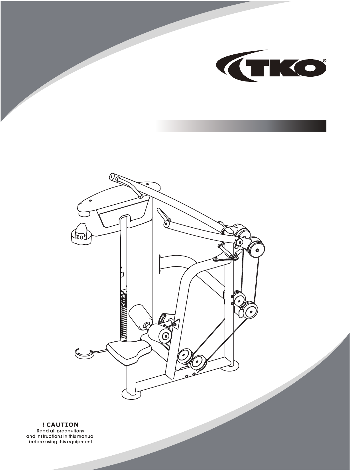
7006-G2
Owner's Manual
LAT PULL

Table Of Contents
CAUTION!
Read all precautions and instructions in this manual before using this equipment.
Please assemble according to the actual Weights you buy !
Important Safety Instructions----------------------------------------------------------- 3
Instructions-------------------------------------------------------------------------------- 5
Exploded View and Parts List------------------------------------------------------------ 6
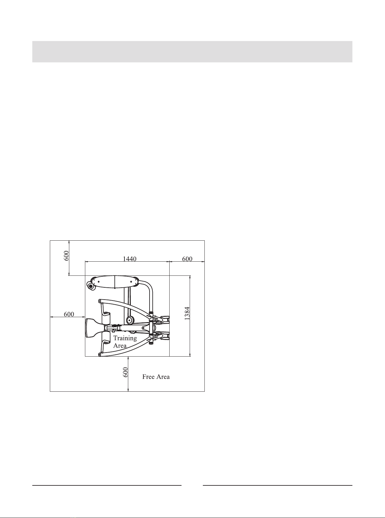
Measurement Guide--------------------------------------------------------------------- 18
Assembly Instructions------------------------------------------------------------------ 19
Assembly--------------------------------------------------------------------------------- 20
Adjust Instructions---------------------------------------------------------------------- 31
Exercise Instructions-------------------------------------------------------------------- 32
Maintenance Schedule------------------------------------------------------------------ 33
General Maintenance Information----------------------------------------------------- 34
Weight Training Tips-------------------------------------------------------------------- 35

3
Important Safety Instructions
Before beginning any fitness program, you should obtain a complete physical
examination from your physician. When using exercise equipment, basic
precautions should always be taken, including the following:
1. Read all instructions before using the equipment.
These instructions are written to ensure your safety and to protect the unit.
2. Use the equipment only for its intended purpose as described in this guide.
Do not use accessory attachments that are not recommended by the
manufacturer: such attachments might cause injuries.
3. The product should only be used on a level surface and is with 0.5 meters
space around the product.
Do not use the equipment outdoors.
4. Do not allow children on or near the equipment. And children are not allowed
to use this equipment.
Teenagers should use this equipment with adult supervision.
5. Do not overexert yourself or work to exhaustion.
Do not attempt to lift more weight than you can control safely.
If you feel any pain or abnormal symptoms, stop your workout immediately
and consult your physician.
6. This equipment is not used as medical apparatus and instruments.
7. Never operate the unit when it has been dropped or damaged.
Never drop or insert anything into any opening in the equipment.
Always check the unit and its cables before each use. Make sure that all
fasteners and cables are secure and in good working condition.
Frayed or worn cables can be dangerous and may cause injury. Periodically
check these cables for any indication of wear.
Keep hands, limbs, loose clothing and long hair well out of the way of moving
parts.
8. Be careful when getting on or off the equipment.
9. Wear proper exercise clothing and shoes for your workout, no loose clothing.
Specifications
Class: S
Maximum Wt. Capacity: 134kg/ 295lbs
Maximum User Weight: 150kg/ 330lbs
Product Total Surface: 1440*1384mm
Product Total Mass: 147.7kg/ 326lbs
Training Area and Free Area
4
Important Safety Instructions
Personal Safety During Assembly
Read each step in the assembly instructions and follow the steps in sequence.
Do not skip ahead. If you skip ahead, you may learn later that you have to
disassemble components and that you may have damaged the equipment.
Assemble and operate the equipment on a solid, level surface. Locate the unit
a few feet from walls or furniture to provide easy access. The equipment is
designed for your enjoyment. By following these precautions and using
common sense, you will have many safe and pleasurable hours of healthful
exercise with the equipment.
5
Instructions
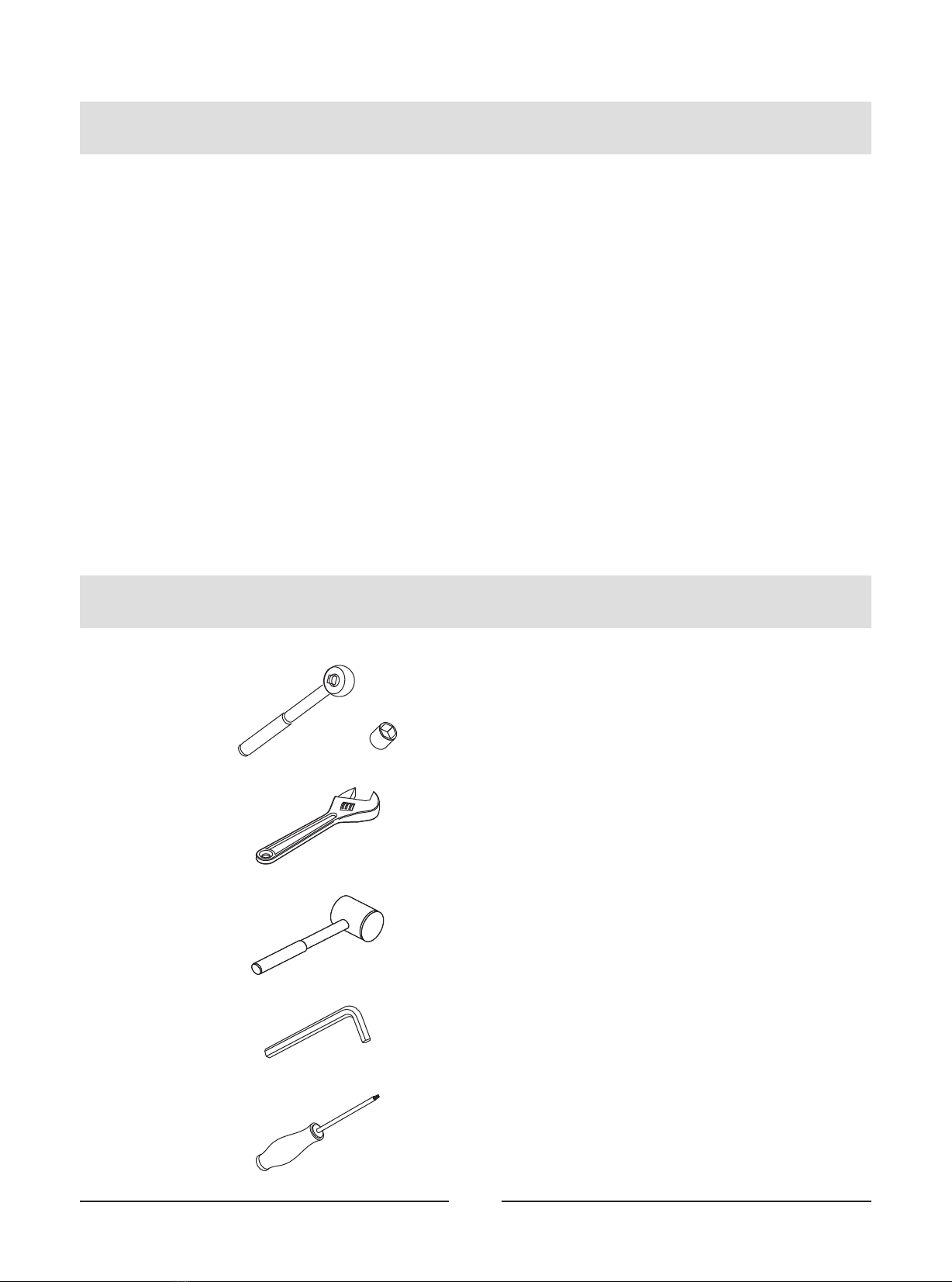
Tools Required
The equipment is designed to provide the smoothest, most effective exercise
motion possible. After assembly, you should check all functions to ensure correct
operation. If you experience problems, first recheck the assembly instructions to
locate any possible errors made during assembly. If you are unable to correct the
problem, call your authorized dealer. Be sure to have your serial number and this
manual when calling. When all parts have been accounted for, continue on.
Ratchet Wrench and Socket
Adjustable Wrench
Rubber Mallet
Hex Key Wrench Set
Phillips Screwdriver
Before beginning assembly please take the time to read instructions thoroughly.
Please use the various lists in this manual to make sure that all parts have been
included in your shipment. When ordering, use part number and description from
the lists. Use only our replacement part when servicing. Failure to do so will void
your warranty and could result in personal injury.
6
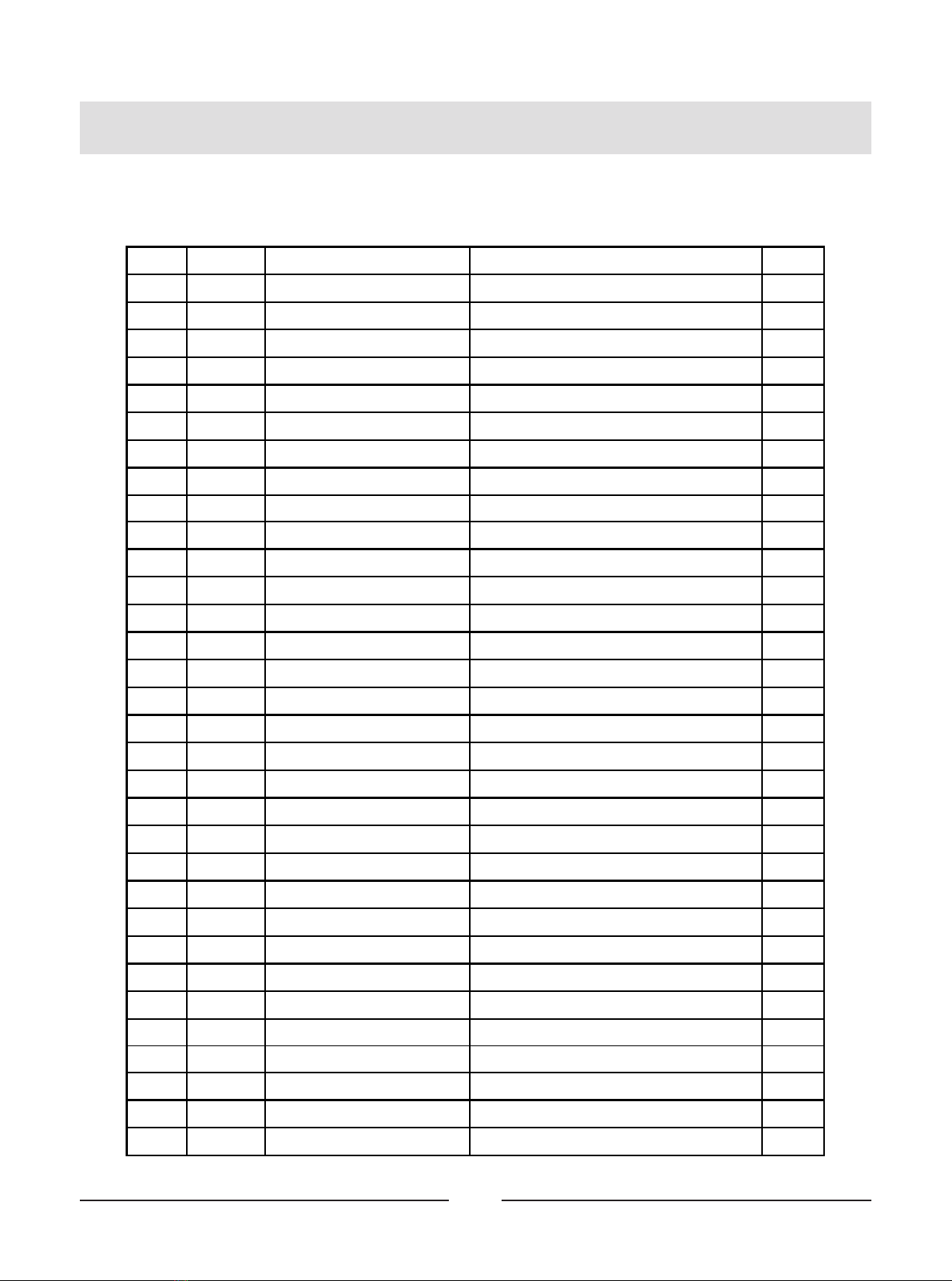
Exploded View and Parts List
Overall
Item No. Grade No. Part No. Description QTY
1 1 IT950101ASSY Weight Stack Frame ASSY 1
2 2 IT950201ASSY Front Frame ASSY 1
3 3 IT950202V1ASSY Top Connection Frame ASSY 1
4 4 IT950203V1ASSY Right Arm Frame ASSY 1
5 5 IT950204V1ASSY Left Arm Frame ASSY 1
6 6 IT950205ASSY Bottom Cross Brace ASSY 1
7 7 IT950206ASSY FOAM Frame ASSY 1
8 8 IT95050300 Rear Connection Frame 1
9 9 IT95020700 DIP Cable 1
10 10 IT95120800 Tension Cable ASSY 1
11 11 PL90101200 V-type Pulley 2
12 12 SD1000B3000ASSY Adjustable Foot Plate 2
13 21 IT950121ASSY Top Bracket ASSY 1
14 22 IT950122ASSY Bottom Bracket ASSY 2
15 23 IT95012300 Rear Bracket 1
16 24 IT95012400 Double Pulley Bracket 1
17 25 IT95016000 Plastic Cover 2
18 26 IT95016400 Pulley Cover 4
20 28 SG500110400V5 4.5" Pulley 7
21 31 IE950221ASSY Shot FOAM ASSY 2
22 42 IT95014200 Top Plate 1
23 44 IT95014400 Guide Rod Φ19*1242 2
24 51 IT95015100 Top Cover 1
25 52 IT95015200 Training Placard Cover 1
26 53 IT95015300 Front Shroud 1
27 54 IT95015400 Right Front Shroud 1
28 55 IT95015500 Top Rear Shroud 1
29 56 IT95015600 Rear Shroud 1
30 76 IT95017600 Seat Pad 1
31 92 IT801210300P11C Cup Holder 1
32 101 FE970113100 Cable Connector Jacket 2
7
Exploded View and Parts List
Overall
Item No. Grade No. Part No. Description QTY
33 102 FE970113200 Cable Connector 2
34 103 FE97211900 Cap Φ60 4
35 104 FE97212000 Circle Ring Φ62.5*5 4
36 105 IT80023000 Weight Rubber Bumper 2
37 106 IT90012000V1 Selector Pin W/Coil 1
38 107 FE97193400 Pulley Spacer 1
39 108 IT95016100 Guide Rod Fixing SleeveΦ25*Φ19*45 2
40 109 IT95016500 Spout Plug Φ16.5*6.88 2
41 110 HFOPT900-04A0602 Spring 2
42 111 GB70BTM12*135DN18 Socket Head Cap Screw M12*135 4
43 112 GB70BTM12*105DN18 Socket Head Cap Screw M12*30 1
44 113 GB70BTM12*30DN18 Socket Head Cap Screw M10*80 2
45 114 GB70BTM10*80DN18 Socket Head Cap Screw M10*80 3
46 115 GB70BTM10*75DN18 Socket Head Cap Screw M10*80 4
47 116 GB70BTM10*70DN18 Socket Head Cap Screw M10*80 2
48 117 GB70BTM10*50DN18 Socket Head Cap Screw M10*80 4
49 118 GB70BTM10*30DN18 Socket Head Cap Screw M10*80 4
50 119 GB70BTM10*25DN18 Socket Head Cap Screw M10*80 4
51 120 GB70M8*20N19 Socket Head Cap Screw M8*20 2
52 121 GB818M6*20DHS2 Cross Recessed Pan Head Screw M6*16 18
53 122 GB818M6*16DHS2 Cross Recessed Pan Head Screw M6*16 4
54 123 GB818M6*10DHS2 Cross Recessed Pan Head Screw M6*16 4
55 124 GB9512DN2 Flat Washer Φ13*Φ24*2.5 8
56 125 GB9510DN2 Flat Washer Φ11*Φ20*2 28
57 126 GB958DN2 Flat Washer Φ9*Φ16*1.6 2
58 127 NM12DN2 Nylon Lock Nut M12 1
59 128 NM10DN2 Nylon Lock Nut M10 15
60 129 NBS6DHS Hex Key S=6 1
61 130 NBS8DHS Hex Key S=8 1
62 131 LW200BS Wrench Φ6*117 1
63 132 YHY Lube 1
64 133 IT80124103 Split Pin Φ11*76 1
8
Exploded View and Parts List
Overall
133
9
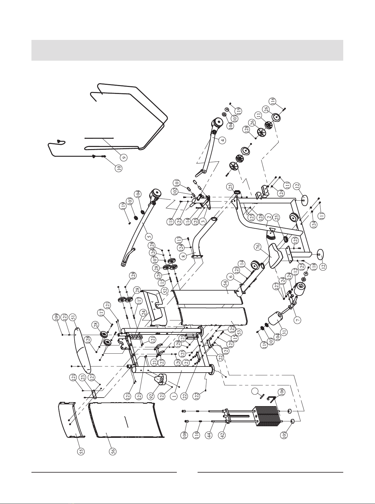
Exploded View and Parts List
Weight Stack Frame ASSY
Item No. Grade No. Part No. Description QTY
1 1.1 IT95010100 Weight Stack Frame 1
2 1.2 GB17880.5M6*16.5DS17 Rivet Nut M6 14
3 1.3 AC32705800 U-nut M6 4
4 1.4 IT95015700 Foot Plate 2
5 1.5 IT95015900 Plastic Block 2
6 1.6 IT95015800 Plug Φ95*81.1 2
7 1.7 GB818M6*20DHS2 Cross Recessed Pan Head Screw M6*20 2
10
Exploded View and Parts List
Front Frame ASSY
Item No. Grade No. Part No. Description QTY
1 2.1 IT95020100 Front Frame 1
2 2.2 IT95057800 4.5" Pulley 1
3 2.3 IT95016400 Pulley Cover 1
4 2.4 IT90021100 Lining Board 1
5 2.5 FE97122100 Pulley Spacer 1 1
6 2.6 IN-S10111200 Rubber Sleeve Φ17*10.5 2
7 2.7 GB70BTM10*25DN18 Socket Head Cap Screw M10*25 1
8 2.8 GB70M8*20DS20 Socket Head Cap Screw M8*20 2
9 2.9 DQ10N19B Flat WasherΦ11*Φ25*2 1
10 2.10 GB958DN2 Flat Washer Φ9*Φ16*1.6 2
11 2.11 NM8DN2 Nylon Lock Nut M8 2
11
Exploded View and Parts List
Top Connection Frame ASSY
Item No. Grade No. Part No. Description QTY
1 3.1 IT95020200V1 Top Connection Frame 1
2 3.2 SA12T_K Joint Bearing M12 2
3 3.3 GB70BTM12*35DN18NL Socket Head Cap Screw M12*35 2
4 3.4 GB6172.1M12DN2 Hexagon Thin Nut M12 4
5 3.5 IT95122200 Urethane Bunper 2
6 3.6 IT90013800P11C Plug RT50*100 1
12
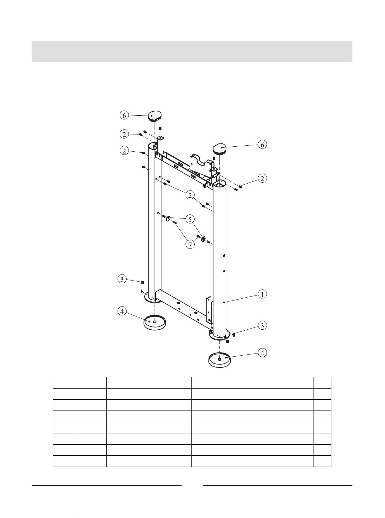
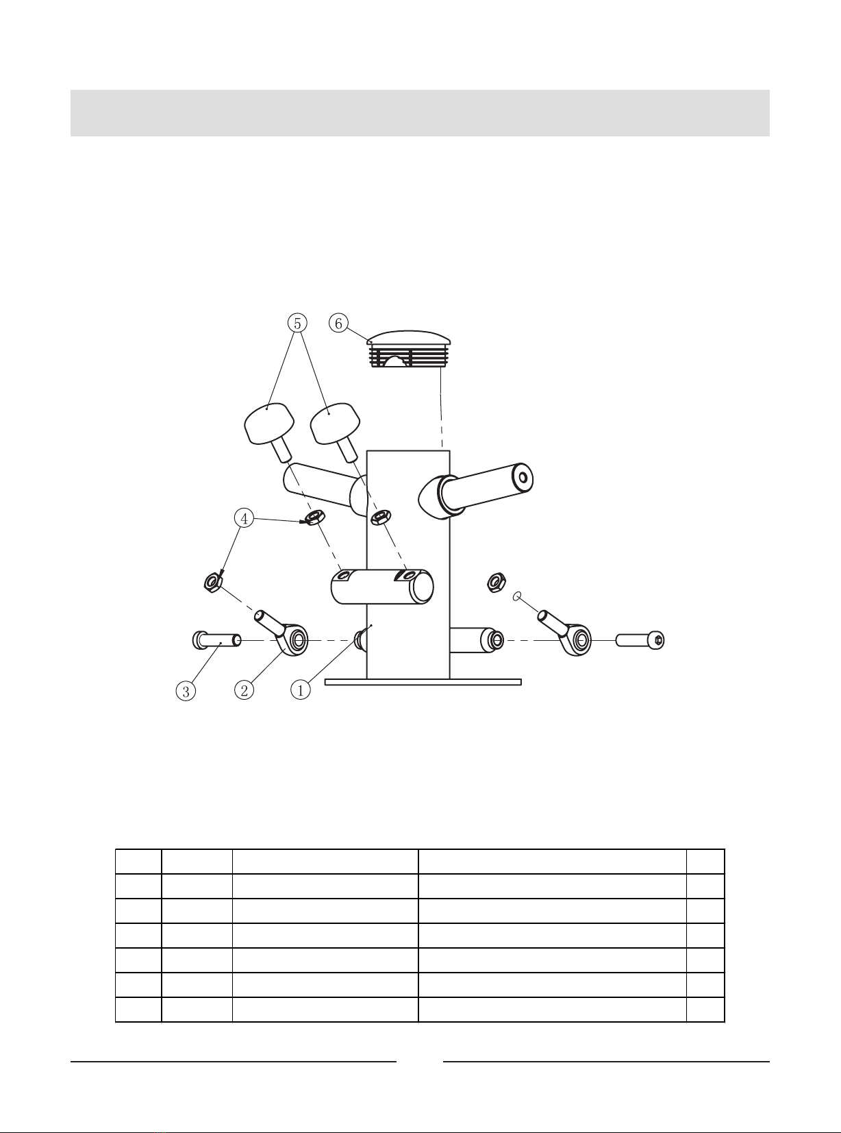
Exploded View and Parts List
Right Arm Frame ASSY
Item No . Grade No. Part No. Description QTY
1 4.1 IT9502030 0V1 Right Arm Frame 1
2 4.2 PL9 0101200 V-type Pulley 1
3 4.3 IT9502110 0 Poise Block 2
4 4.4 FE97 211 900 Cap φ60 1
5 4.5 IT9010220 0 Aluminum Grip Ring 1
6 4.6 IT9502210 0 Aluminum Grip Cap 1
7 4.7 IT9503210 0 Grip 1
8 4.8 GB2 766006-2 RSC3NBK Deep Groove Ball Bearing φ25*φ5 2*15 2
9 4.9 GB7 0BTM10 *100 DN1 8 Socket Head Cap Screw M10*100 1
10 4.10 GB7 0BTM10 *25DN18 Socket Head Cap Screw M10*25 1
11 4.11 YZGB771 0-32 *3.2 N19 Socket Set Screw 10- 32UNF*3.2 4
12 4.12 NM10DN2 Nylon Lock Nut M10 1
13
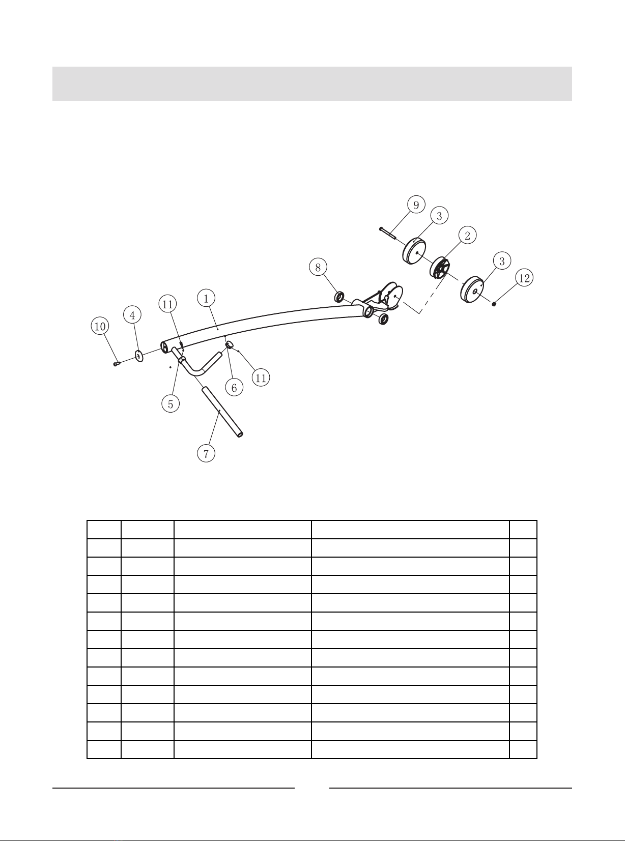
Exploded View and Parts List
Left Arm Brace ASSY
Item No . Grade No. Part No. Description QTY
1 5.1 IT9502040 0V1 Left Arm Frame 1
2 5.2 PL9 0101200 V-type Pulley 1
3 5.3 IT9502110 0 Poise Block 2
4 5.4 FE97 211 900 Cap φ60 1
5 5.5 IT9010220 0 Aluminum Grip Ring 1
6 5.6 IT9502210 0 Aluminum Grip Cap 1
7 5.7 IT9503210 0 Grip 1
8 5.8 GB2 766006-2 RSC3NBK Deep Groove Ball Bearing φ25*φ5 2*15 2
9 5.9 GB7 0BTM10 *100 DN1 8 Socket Head Cap Screw M10*100 1
10 5.10 GB7 0BTM10 *25DN18 Socket Head Cap Screw M10*25 1
11 5.11 NM10DN2 Nylon Lock Nut M10 1
12 5.12 YZGB771 0-32 *3.2 N19 Socket Set Screw 10- 32UNF*3.2 4

14
Exploded View and Parts List
FOAM Frame ASSY
Bottom Cross Brace ASSY
Item No. Grade No. Part No. Description QTY
1 6.1 IT95020500 Bottom Cross Brace 1
2 6.2 IT95057800 4.5" Pulley 1
3 6.3 IT95016400 Pulley Cover 1
4 6.4 FE97122100 Pulley Spacer 1 1
5 6.5 GB70BTM10*25DN18 Socket Head Cap Screw M10*25 1
6 6.6 DQ10N19B Flat WasherΦ11*Φ25*2 1
Item No. Grade No. Part No. Description QTY
1 7.1 IT95020600 FOAM Frame 1
2 7.2 IT95021600 Pin 1
3 7.3 IF81165000 Bolt 2
4 7.4 IT90021200V1 Axle Φ25.4*Φ12.5*72.5 1
5 7.5 M02502000 SpacerΦ38*Φ32*Φ25.4*18 2
15
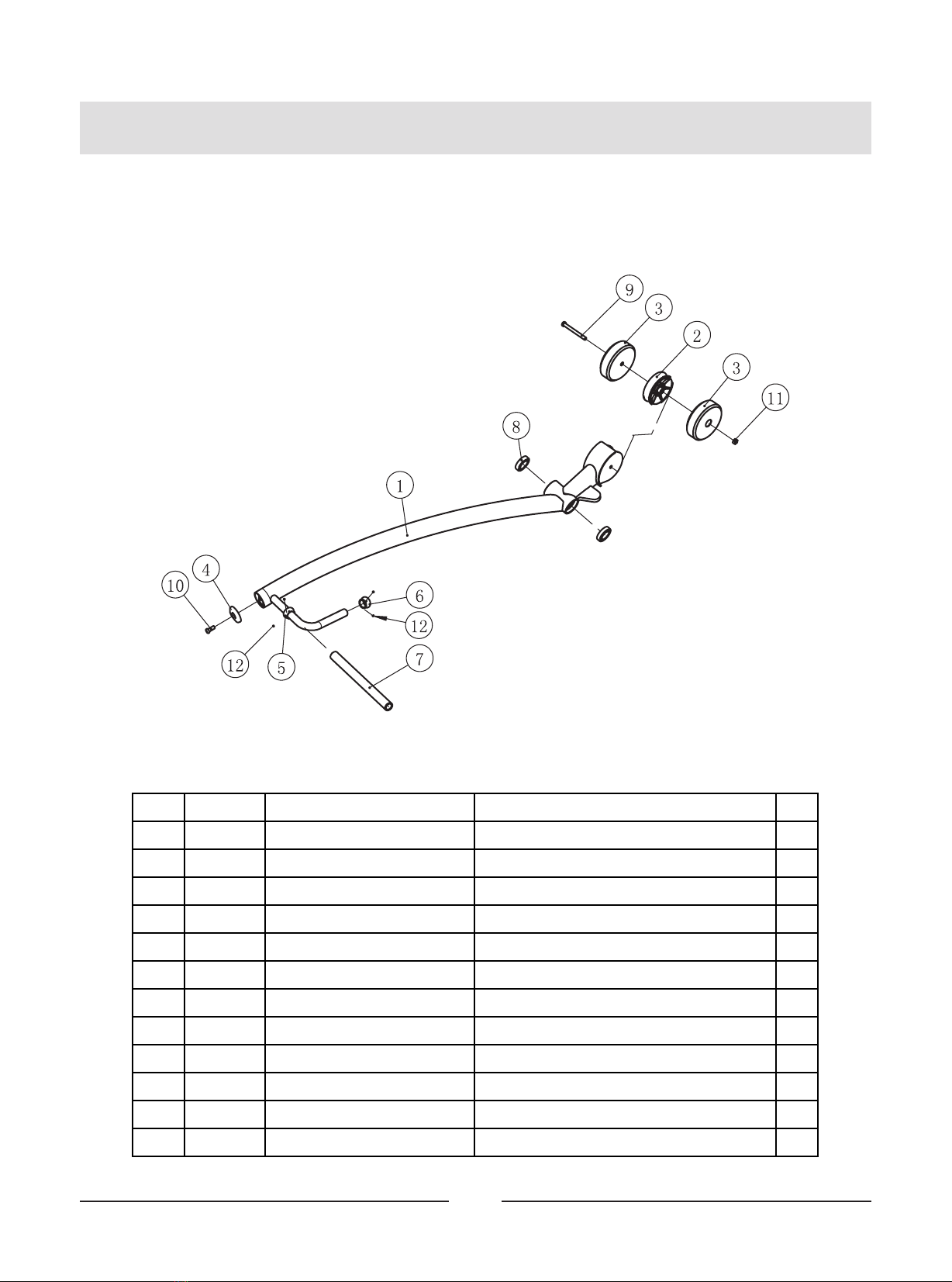
Exploded View and Parts List
Tension Cable ASSY
Item No. Grade No. Part No. Description QTY
1 10.1 IT95120801 Tension Cable 1
2 10.3 HF900-03A1002 Hex Flange Nut 1
3 10.5 BNH0562 Strap Bracket 1
4 10.6 GB70M10*35*15DN18 Socket Head Cap Screw M10*35 1
5 10.7 NM10DN2 Nylon Lock Nut M10 1
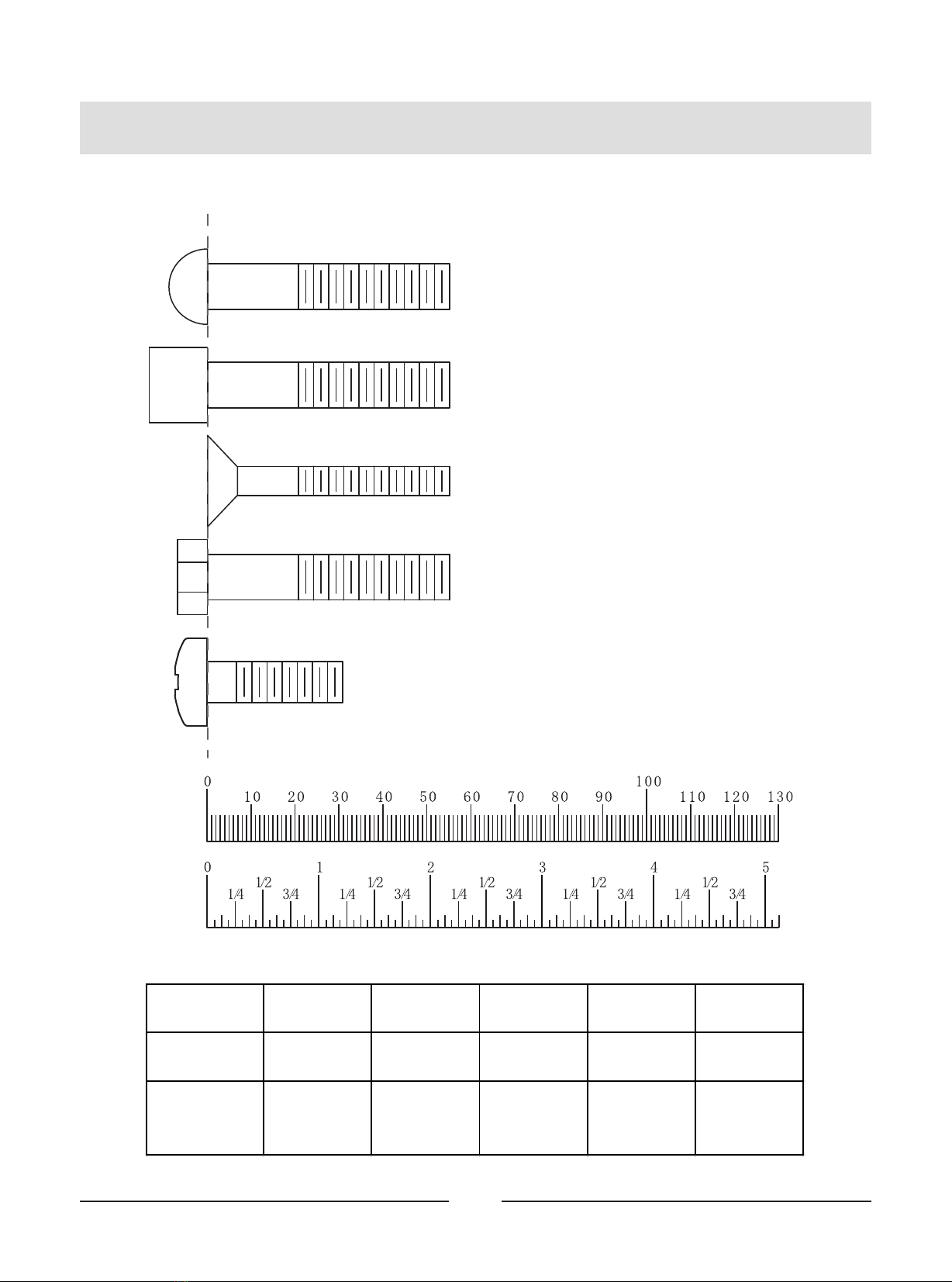
Inches
Millimeters
BHCS = Button Head Cap Screw
SHCS = Socket Head Cap Screw
FHCS = Flat Head Cap Screw
HHB = Hex Head Bolt
Measurement Guide
Diameter of bolt
(mm/inch) M6(1/4") M8(5/16") M10(3/8") M12(1/2") M16(5/8")
Tightening
torque (N.m) 9~12 22~30 45~59 78~104 193~257
Operational
methods for
adult men
The strength of
the wrist
The strength of
the wrist and
forearm
The strength of
the entire arm
The strength of
the arm and
upper body
with all strength
16
CRPHS = Cross Recessed Pan
Head Screw

17
Assembly Instructions
Assembly of the equipment takes professional installers about 2 hours. If this
is the first time you have assembled this type of equipment, plan to spend
more time. It is strongly recommended to assemble the equipment by
professional installers. You may find it quicker, safer, easier to assemble this
equipment with the help of a friend, as some of components may be large,
heavy or awkward to handle alone. It is important that you assemble your
product in a clean, clear, uncluttered area. This will enable you to move around
the product while you are fitting components and reduce the possibility of
injury during assembly.
As with any assembled part, proper alignment and adjustment is critical. While
tightening the fasteners, be sure to leave room for adjustments. Do not fully
tighten the fasteners until instructed to do so. Be careful to assemble the
components in the sequence presented in this guide.
NOTE
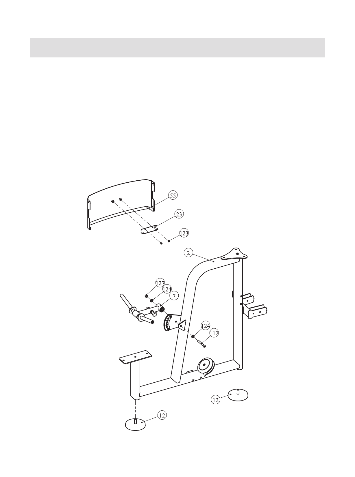
STEP 1
1. Attach two Adjustable Foot Plates (#12) to the Front Frame ASSY (#2).
2. Attach the Rear Bracket (#23) to the Top Rear Shroud (#55) using:
two M6*10 CRPHS (#123)
3. Attach the FOAM Frame ASSY (#7) to the Front Frame ASSY (#2) using:
one M12*105 SHCS (#112)
two Φ13*Φ24*2.5 Flat Washer (#124)
one M12 Nylon Lock Nut (#127)
Note: Wrench Tighten Bolts.
Assembly
18
Assembly
19
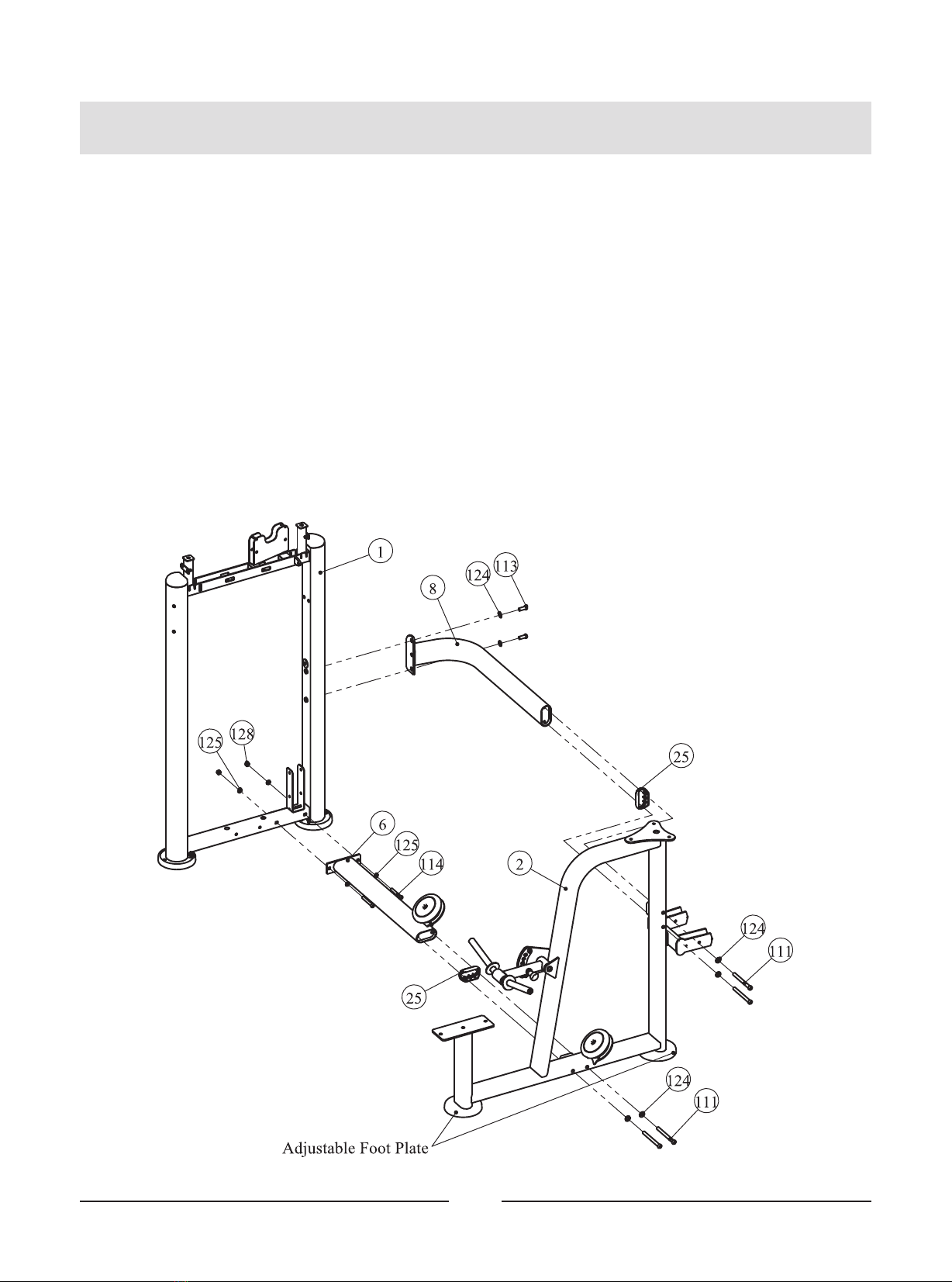
STEP 2
Attach the Bottom Cross Brace ASSY (#6) and the Rear Connection Frame (#8) to the
Weight Stack Frame ASSY (#1) and the Front Frame ASSY (#2) using:
two Plastic Cover (#25)
four M12*135 SHCS (#111)
two M12*30 SHCS (#113)
two M10*80 SHCS (#114)
two M10 Nylon Lock Nut (#128)
four Φ11*Φ20*2 Flat Washer (#125)
six Φ13*Φ24*2.5 Flat Washer (#124)
Note: 1. Wrench Tighten Bolts and Nylon Lock Nuts.
2. Adjust the Adjustable Foot Plates to make the machines stable.
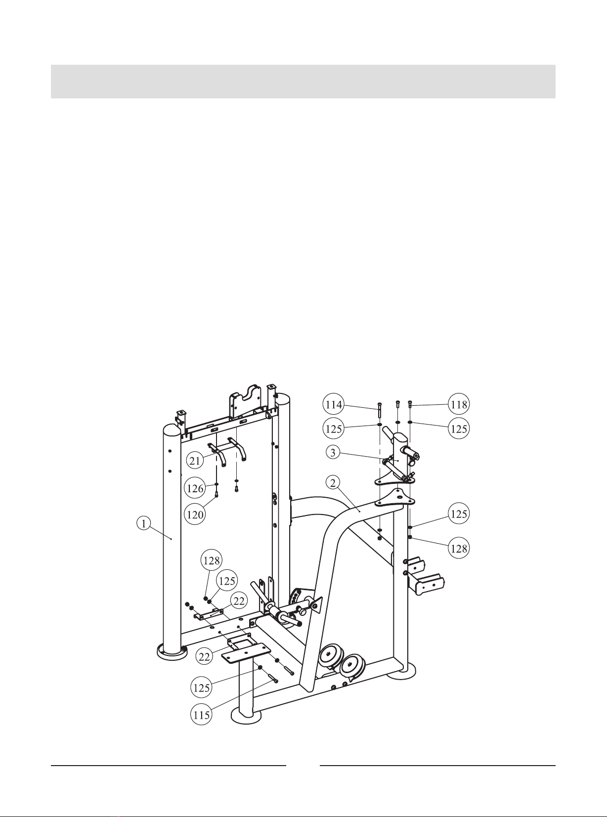
STEP 3
1. Attach the Top Connection Frame ASSY (#3) to the Front Frame ASSY (#2) using:
one M10*80 SHCS (#114)
two M10*30 SHCS (#118)
six Φ11*Φ20*2 Flat Washer (#125)
three M10 Nylon Lock Nut (#128)
2. Attach the Top Bracket ASSY (#21) and two Bottom Bracket ASSY (#22) to the Weight
Stack Frame ASSY (#1) using:
two M8*20 SHCS (#120)
two Φ9*Φ16*1.6 Flat Washer (#126)
two M10*75 SHCS (#115)
four Φ11*Φ20*2 Flat Washer (#125)
two M10 Nylon Lock Nut (#128)
Note: Wrench Tighten Bolts and Nylon Lock Nuts.
Assembly
20
Table of contents
Other TKO Fitness Equipment manuals


