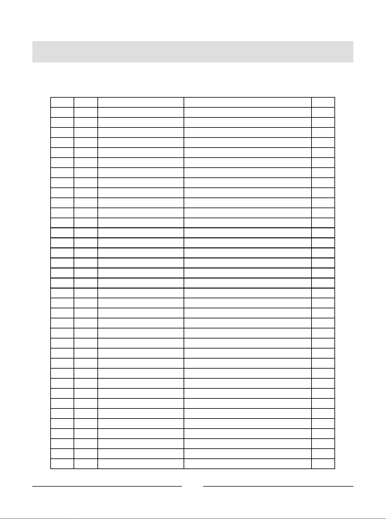
ItemNo. Gr ade No. Part No. Description QTY
37 37 HFOPT900-04A0602 Spring 2
38 38 M02701000 Tube Plug □50 4
39 39 IT90012000V1 Selector Pin W/Coil 1
40 40 IT80023000 Weight Rubber Bumper Φ63.5*Φ19*25.4 2
41 41 IT95081900 Support Sleeve 4
42 42 FE97122100 Bushing Φ22 1
43 43 IT80081900V1 Cap Φ55 1
44 44 IT80083500 Bushing Φ32 2
45 45 FS552300 Rubber BumperΦ63.5 2
46 46 GB70M4*15*15DN2 Flat Head Cap Screw M4*15 1
47 47 GB70M8*20N19 Flat Head Cap Screw M8*20 2
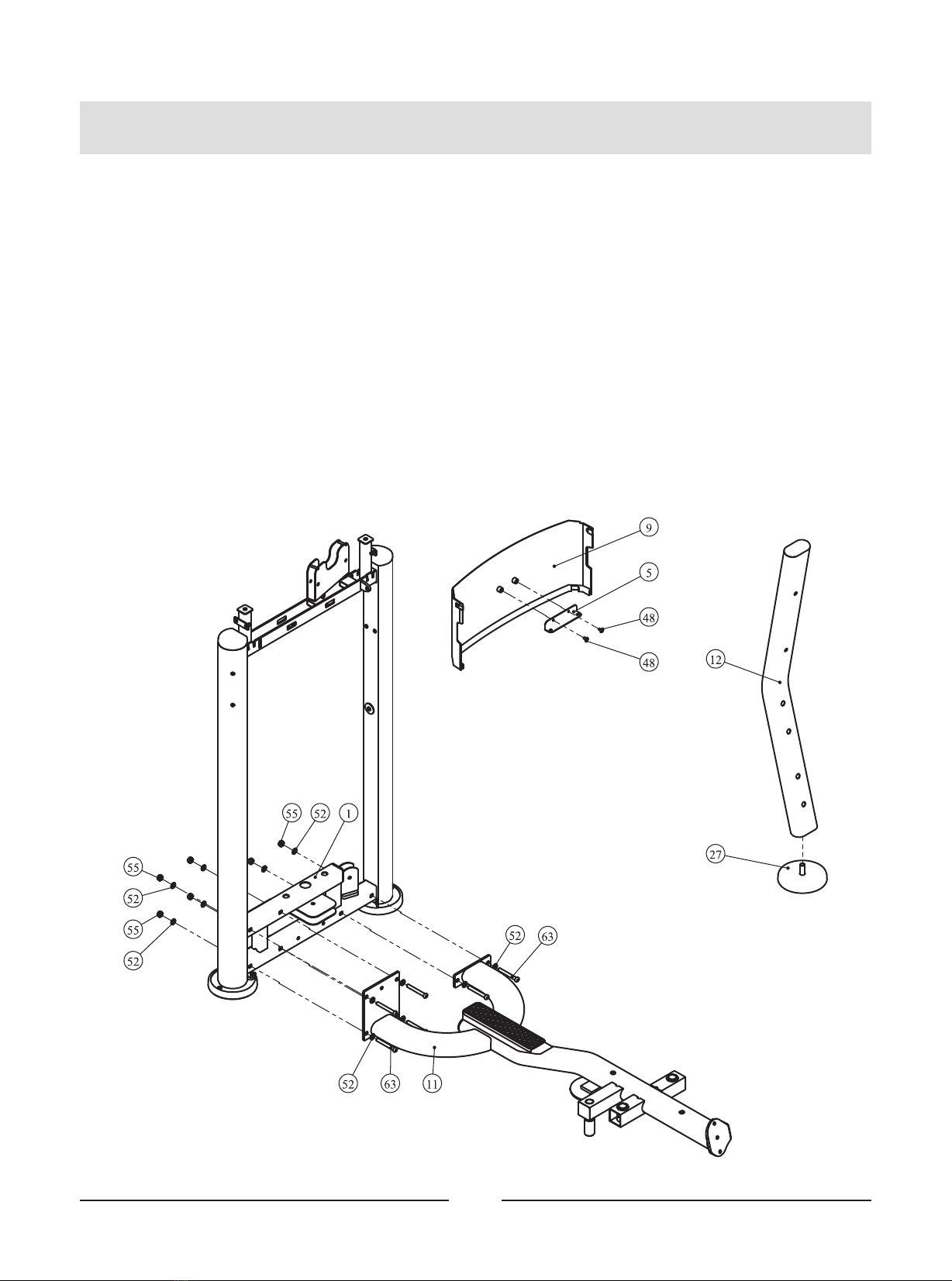
48 48 GB818M6*10DHS2 Cross Reces sed Pan Head Screw M6*10 4
49 49 GB818M6*16DHS2 Cross Reces sed Pan Head Screw M6*16 4
50 50 GB818M6*20DHS2 Cross Reces sed Pan Head Screw M6*20 18
51 51 GB958DN2 Flat Washer Φ9*Φ16*1.6 2
52 52 GB9510DN2 Flat Washer Φ11*Φ20*2 39
53 53 GB9512DN2 Flat Washer Φ13*Φ24*2.5 4
54 54 HDQ10DN2 Arc Washer Φ11*Φ21*1.5 4
55 55 NM10DN2 Nylon Lock Nut M10 17
56 56 NM12DN2 Nylon Lock Nut M12 2
57 57 GB894.125FH12 Circlips For Shaft d0=25 3
58 58 CNLM10*30*30DN20 Socket Countersunk Head Cap Screw M10*30 2
59 59 GB70BTM10*25DN18 Sock et Head Cap Screw M10*25 6
60 60 GB70BTM10*30DN18 Sock et Head Cap Screw M10*30 4
61 61 GB70BTM10*50DN18 Sock et Head Cap Screw M10*50 7
62 62 GB70BTM10*75DN18 Sock et Head Cap Screw M10*75 6
63 63 GB70BTM10*80DN18 Sock et Head Cap Screw M10*80 9
64 64 GB70BTM10*100DN18 Sock et Head Cap Screw M10*100 2
65 65 GB70BTM12*105DN18 Sock et Head Cap Screw M12*105 2
66 66 FE97122300 Threaded Column 1
67 67 IT95016500 Spout Plug Φ16.5*6.88 2
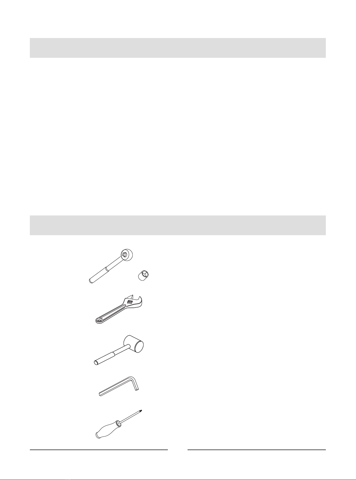
68 68 NBS3DHS Hex Key S=3 1
69 69 NBS6DHS Hex Key S=6 1
70 70 NBS8DHS Hex Key S=8 1
71 71 LW200BS Wrench Φ6*117 1
72 72 YHY Lube 1