TKR Group 81 29 2 208 034 User manual
81 29 2 208 034
R6-22.06-V1
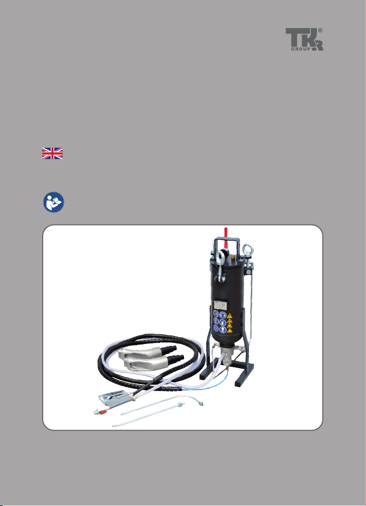
Granule jet blasting device PG 5–8
Translation of the original instructions

2

3
This instruction manual is protected by copyright. No use outwith the strict limitations of copyright legislation without
the consent of the manufacturer is permitted, this rendering the oender liable to criminal prosecution. This applies
likewise for the extraction of individual illustrations and the use of texts in extract form.
1.1 General instructions 4
1.2 Labelling 6
2.1 Use for intended purpose 7
2.2 Danger sources 8
2.3 Safety devices on the equipment 10
2.4 Safety measures at the installation site 12
3.1 Unpacking the device 13
3.2 Identication and description of the device
components 13
3.3 Device components 14
3.4 Technical Data 16
4.1 Operation of the granule jet blasting device 17
4.2 Granule jet blasting device preparation and connection 18
4.3 Filling with blasting material 20
4.4 Connect vacuum adapter to vacuum cleaner 24
4.5 Attach blasting lance to handle 25
4.6 Starting the cleaning process 26
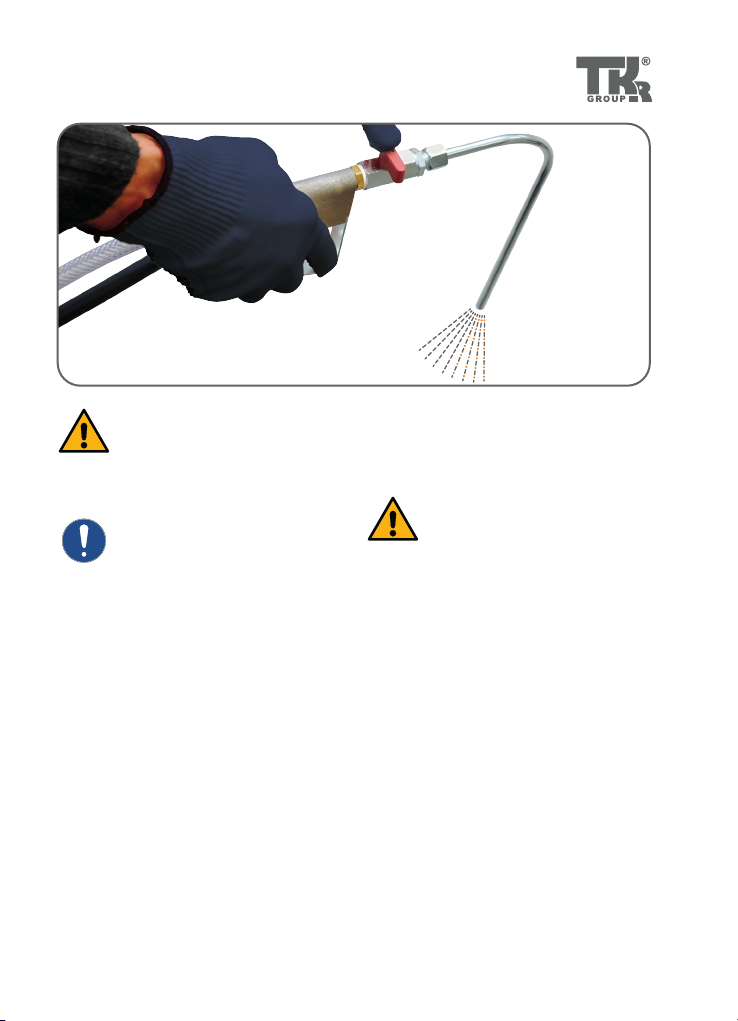
4.7 Blasting 27
4.8 Cleaning the inlet valves and the inlet channel 28
4.9 Taking the device out of service 30
5.1 Maintenance / cleaning 31
5.2 Spare parts and accessories 34
5.3 Disposal 36
5.4 Warranty & Service 37
5.5 Declaration of Conformity 38
1.
2.
3.
4.
5.

4
State-of-the-art
This tool is state-of-the-art technology.
To ensure that the equipment operates
safely, it must be operated in a proper and
safety-conscious manner.
Technical changes
In the interests of quality assurance, we
reserve the unrestricted right to carry out
technical changes as a result of further
technological developments and product
improvements without prior notication.
Reading the owner’s manual
Before using the tool, make
sure you read the owner’s man-
ual carefully and understand
it. This manual must always be
available where the product is
used.
Handling
All the actions necessary to ensure correct
operation are described in the owner’s
manual. Any working methods other than
those approved by the manufacturer are
prohibited.
Faults
If faults occur, the operator may only
eliminate those faults through their own
actions where the corresponding remedy
is described.
Warranty
The manufacturer accepts no liability for
damage or injury caused by improper re-
pair or the use of third-party replacement
parts.
No warranty will be provided for damage
caused to the device due to the tool being
used incorrectly.
Environment
Make sure that the tool is set up in a work
area which is free from sources of corrosive
liquids, greases or oils.
Declaration of Conformity
The tool has been manufac-
tured in accordance with inter-
national guidelines. The rele-
vant declaration of conformity
(CE, UKCA, CB) is included with
this owner’s manual.
1.1 General instructions
5.5

5
Risk of damage to the tool
The tool must only be used as
described in the instruction
manual. It is expressly forbid-
den to misuse the tool or to use
it for any other purpose. Please
make sure that you and your
sta handle the tool correctly.
Risk of injury
In addition to the owner’s man-
ual and the binding provisions
of the accident prevention
regulations which apply in the
country and at the place of use,
you must also comply with the
general (accepted) rules for
safe and professional working.
Technical personnel
Only trained and instructed personnel are
authorized to carry out the repair / main-
tenance work on the vehicles and vehicle
components concerned.
6
Some chapters in this instruction manual use internationally recognised warning
symbols, warning notes and general instruction symbols.
The individual symbols are explained below. Follow all the instructions and safety
rules.
1.2 Labelling
Instruction manual
general instructions
Observe the general
instructions
Wear face mask
Wear hearing protection
Wear gloves
Wear protective clothing
Warning
General source of danger
Warning
System under pressure
Risk of hearing damage
Warning - noise with high
sound pressure level
Please note the following.
Arrow to clarify
pressing together
Arrow indicating direction
For further information
see chapter...
Audibly engage
Shorten
Blow out with air
Clean with air/granule mixture
CE-mark
UK Conformity Assessment

7
2.1 Use for intended purpose
The granule jet blasting device complies
with the machinery directive 98/37 EC
and is used for processing the surface of
metal using a grainy blasting material,
that is blasted onto the surface that is
being processed. The blasting material is
transported using compressed air.
The GP 5-8 granule jet blasting
device is used for removing car-
bonized material from the inlet
channel and valves of combus-
tion engines.
The jet blasting device may
only be operated in combina-
tion with the vacuum adapters
that are approved for the rele-
vant engine type and a vacuum
cleaner with sucient suction
power.
Unauthorised modications or
changes to the device are not
permitted for safety reasons.
8
Never throw or drop the granule jet blasting
device.
The granule jet blasting device may only be
used at ambient temperatures of between 5
°C and 50 °C.
The granule jet blasting device must not be
used in potentially explosive areas!
The device must never be operated without
suitable protective clothing, such as a safety
mask and safety shoes. Risk of injury!
Before carrying out mainte-
nance or cleaning work and
always before lling the de-
vice with granules, the com-
pressed air supply must be
disconnected and the device
depressurised.
The granule jet blasting device
may only be operated with
compressed air.
The granule jet blasting device is safe if
used for its correct purpose.
If it is used incorrectly and/or
negligently by untrained per-
sonnel, serious injuries could
be caused by the escaping
granules.
The blasting probe must never
be used without the provided
vacuum adapter and vacuum
equipment with adequate
power.
Never direct the blasting probe
at persons or look into the
opening of the blasting probe.
Risk of injury!
The device must only be oper-
ated using hoses that are ap-
proved for the purpose of use
and the operating pressure of
the device.
The device may only be used
by trained personnel.
2.2 Danger sources
5.1

9
The granule jet blasting de-
vice must always be set up
on a level surface or the oor
of the workshop. The device
must not be set up on ta-
bles, workbenches or other
objects. (Container is under
pressure!)
2.4 Hoses and supply lines must
be routed in such a way that
they cannot be damaged or be-
come trapped! The hoses must
also be routed in a way that
prevents people from tripping
over them.
10
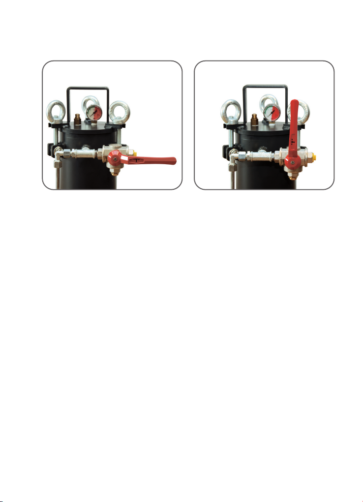
2.3.1 2.3.2
2.3 Safety devices on the equipment
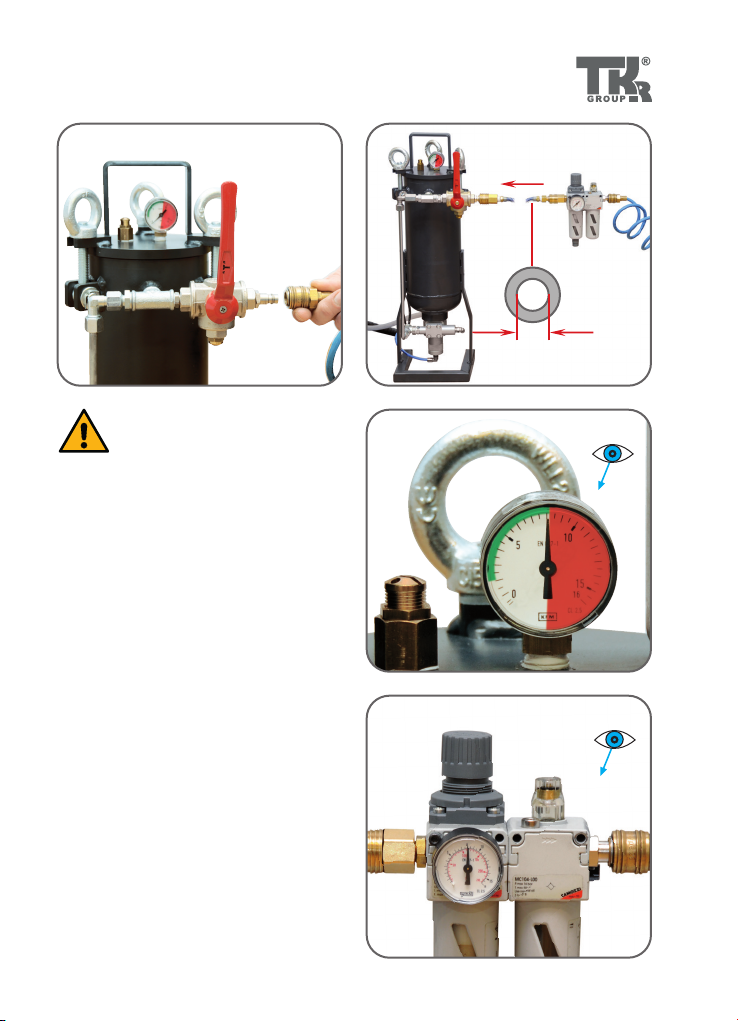
Fig. 2.3.1
There is a 3-way ball valve on the granule
container that applies compressed air to
the container and the control system in the
operating position.
Fig. 2.3.2
In the„O“ position the container and the
control system are depressurised.
Fig. 2.3.3
There is a 2-way ball valve on the handle of
the blasting lance. This can be operated if
a control function fails. If the ball valve is
closed, no air or other blasting material can
exit from the lance.
Item A:
relieve
Item B:
work item
11
2.3.3
7
If a control function fails, the
device must be taken out of
service immediately and re-
paired by a trained expert!
There is a pressure gauge on
the granule container. The
maximum operating pres-
sure of the device may never
exceed 8 bar. A safety valve is
installed on the granule con-
tainer that controls the max-
imum operating pressure of
the device. The valve opens
at pressure of approx. 8.5 bar.
If the safety equipment mal-
functions, the device must be
taken out of service immediate-
ly! The device should undergo
preventive maintenance at
least once per annum by a spe-
cialist company!

12
2.4.12.4.1
2.4 Safety measures at the installation site
Fig. 2.4.1
The surface on which the device is installed
must be level, load-bearing and stable in ac-
cordance with the weight of the device.
The device may only be used in combination
with the suction adapters that are provid-
ed for the respective motor type and an ade-
quately dimensioned vacuum cleaner.
Hoses and supply lines must be routed so
that they do not damage the device and
cannot become trapped! The hoses must
also be routed in such a away that they can-
not be tripped over.
13
3.1.1
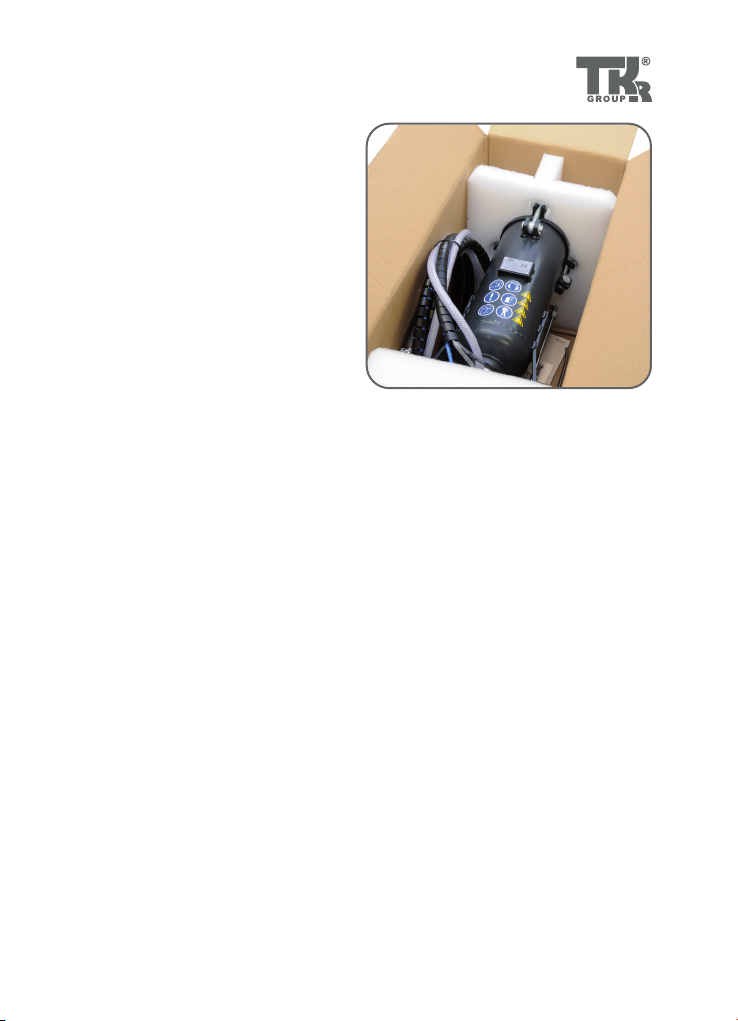
3.1 Unpacking the device
3.2 Identification and description of the
device components
• Place box on a level surface
• Open box and carefully remove
the device
• Check the accessories
- Operating instructions
- Granule container with connected
hose package and handle
- Straight blasting lance
- Angled blasting lance
- Possibly other accessories,
see delivery note
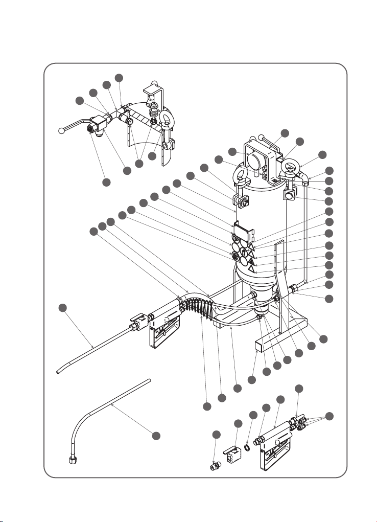
Main elements of the granule jet blasting device
Granule blasting material container with 3-way ball valve, granule control valve, com-
pressed air control valve, pressure gauge and safety valve.
Hose package with granule transportation hose, and three colour-coded control hoses.
Handle with 2-way ball valve and connection for the blasting lance. The control function in
the handle is activated using two control valves connected in series. The operating lever is
equipped with a safety device to prevent unintentional reactivation.
14
32
38
31
34
21
20
9
22
24
49
18
25
37
27
7
28
7
12
42
46
43
47
45
48
15
26
19
3
1
13
2
17
6
33
44
41
40
39
51
50
30
5
35
10
11
49
18
14
15
36
16
4
17
23
29
8
3.3.1
3.3 Device components

15
No. Title
1 Eye bolt
2 Annular nut
3Pin
4 O-ring
5 Split pin
6 Handle
7Control block
8 PVC hose Ø 14 mm
9 Handle
10 Relief valve
11 Pressure gauge Ø 50 mm
12 Kapsto plastic cover
13 Countersunk screw
14 Double nipple
15 T-piece
16 Exhaust valve
17 3-way ball valve
18 Straight threaded male
connector
19 Ermeto pipe 8x1
20 Bulkhead nipple
21 2-way ball valve
22 Threaded nozzle
23 Nozzle, straight
24 Straight insert nuts
25 Elbow tting
26 Screw-in tting
27 Straight male connector
28 Double nipple
29 Elbow tting connection
30 Disc
No. Title
31 Hose, black Ø 6 mm
32 Hose, blue Ø 6 mm
33 Hose, transparent Ø 6 mm
34 Nozzle, bent
35 Granule container
36 Kapsto sealing screw
37 Press nipple
38 Protective hose
39 Follow manual
40 Observe the general information
41 Wear face mask
42 Wear ear protection
43 Wear gloves
44 Wear protective clothing
45 Warning! System under
pressure
46 Warning! General source of
danger
47 Warning against damage to
hearing
48 Warning against high levels of
noise
49 PVC washer for 1/4“
connection
50 Hose clamp
51 Type plate

16
290
620
2
3
1
3.4.1
3.4 Technical Data
1 = Control air, transparent hose
2 = Main air, black hose
3 = Granules supply, blue hose
Blasting lance, 3/3-way
straight control valve
Blasting lance,
bent
Length 290 mm
Width ca. 280 mm
Height 620 mm
Max. operating pressure 8 bar
Container volume 5 l
Weight 15.5 kg
Hose package working length 4 m
Length and weight without hoses
17
4.1 Operation of the granule jet
blasting device
• Fill with blasting material.
• Connect vacuum adapter to vacuum device.
• Attach blasting lance to handle.
• Connect granule jet blasting device to the compressed air supply.
• Start the cleaning process.
• Blasting with air / blowing out.
• Blasting with air/granule mixture / cleaning.
• Cleaning the inlet valves and the inlet channel.
• Taking device out of service.
• Maintaining the granule jet blasting device.
Always check the condition of the hoses before starting up the device!
Stop using defective hoses immediately. Risk of injury!

18
4.2.14.2.1 4.2.2
4.2.44.2.4
G1/4“
4.2.3
G1/4“ R1/4“
Ø 6 mm
4.2 Granule jet blasting device preparation
and connection
Fig. 4.2.1
The device is supplied from the factory
without a compressed air coupling. The ball
valve has a connecting thread with a female
thread of G ¼“. The thread is tted with a
closing cap.
Fig. 4.2.2 - 4.2.3
Insert a suitable compressed air connec-
tion with seal into the thread.
Remove the closing cap.
Fig. 4.2.4
Tighten the compressed air connection
using a suitable tool.
19
4.2.5 4.2.6
≥ Ø 6 mm
4.2.8
4.2.7
The device may only be
operated using dry, oil-free
compressed air!
Fig. 4.2.6
The granule jet blasting device may only
be operated with an external supply
unit with variable operating pressure!
Fig. 4.2.7 - 4.2.8
The operating pressure of the device
should be between 6 and 8 bar, and may
never exceed an operating pressure of
8 bar! 6–8 bar
max. 8 bar
20
4.3.2
4.3.1
4.3.3
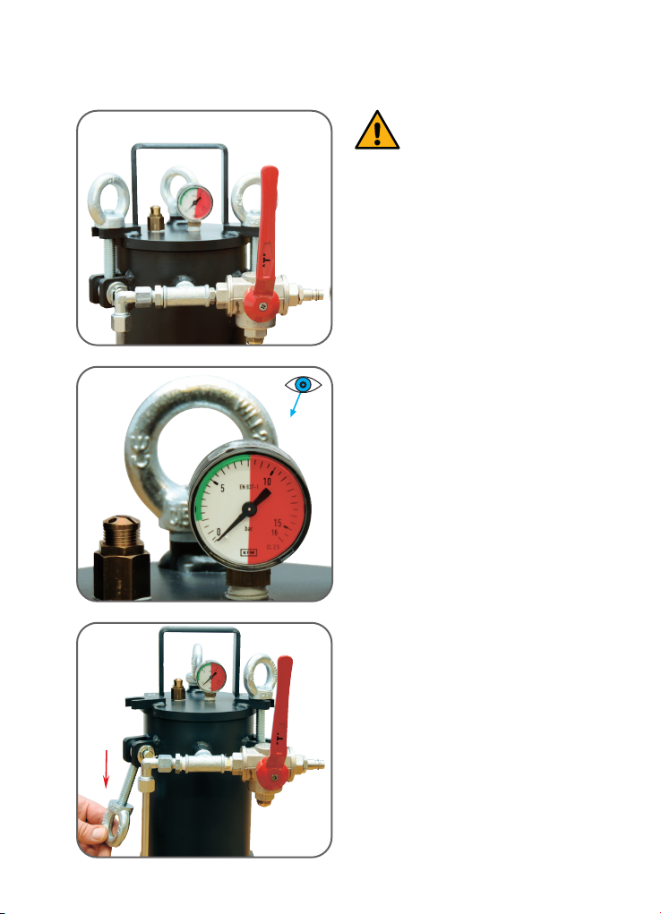
Attention!
Device may only be lled if
container is depressurised
and the air supply line has
been disconnected.
Fig. 4.3.1
3-way ball valve in„Relieve“ position
Fig. 4.3.2
Pressure gauge must not be indicating any
pressure
Fig. 4.3.3
Undo eye bolts and swivel out swivelling
screw tting
4.3 Filling with blasting material
Table of contents
Popular Cleaning Equipment manuals by other brands


Omegasonics
Omegasonics RESTORATION PRO 3600XW Operation & instruction manual

Sebo
Sebo ET-1 instruction manual

Abicor Binzel
Abicor Binzel TCS Compact operating instructions

Westward
Westward 22XP35 Operating instructions and parts manual

Kärcher
Kärcher 15741040 manual

Miele
Miele EVS 7010 Operating and installation instructions