TKR Group 83 30 2 457 168 User manual
Test box set
Instruction manual
83 30 2 457 168
Original instruction manual

22
?
Test boxset
Instruction manual
Prüfboxenset
Betriebsanleitung
8330 2 457 168
Originalbetriebsanleitung
Translationof the original instruction manual
This instruction manual is copyright-protected. Any use outside the limits of copyright law without the consent of the manufacturer is inadmissible and
punishable. This also applies to the extraction of individual illustrations and use of text excerpts.
Digital instruction manual
Europe
Worldwide
www.tkr-service.comUSB stick
Digital instruction manual
Europe
Worldwide
Instruction manual

33
Safety
1.1 Notes for the instruction manual 4
1.2 Explanation of symbols 4
1.3 Delivery contents 5
1.4 Labels 6
1.5 Safety instructions 7
Technical data
2.1 Technical data 8
2.2 Device components 9
2.3 Operating conditions 9
Application
3.1 Principles for handling the test box 10
3.2 Intended use 10
3.3 Startup - Preparation 11
3.4 Connecting the BMW adapter cable 13
3.5 Connecting the test box to the vehicle 14
3.6 Possible applications 15
3.7 Storing the test box 16
Maintenance
4.1 Maintenance 17
4.2 Troubleshooting 17
4.3 Spare parts 18
Service
5.1 Disposal 18
5.2 EU Declaration of Conformity 19
1.
2.
3.
4.
5.

44
1.1 Notes for the instruction manual
Observe the instruction
manual!
Observe the general
instructions!
Prohibited for persons with
pacemakers
Attention!
General hazard
Warning: Dangerous
electrical voltage
1.2 Explanation of symbols
In this instruction manual, some sections use internationally recognised warning symbols, warning notes, and
general instruction symbols.
The individual symbols are explained below. Follow all the instructions and safety rules.
Ground device tag
IN control unit
OUT car
Please pay attention to...
Audible locking
Turn clockwise
Arrows to indicate
compression
For further information,
see section...
Arrow showing direction
State of the art
The BMW test box set reflects the latest technological
standards. To ensure that the device functions properly,
it must be operated in a professional and safety-conscious
manner.
Technical modifications
In the interests of quality assurance, we fully reserve the
right to carry out technical modifications on the basis of
further technological developments and product improve-
ments, without prior notice.
Read the instruction manual
Before using the test box set, the instruction manual must
be carefully read and understood. This manual must
always be available on site where the product is used. In
addition to the instruction manual and the applicable rules
for accident prevention in the country and place of use, the
generally recognised regulations for safe and professional
work must be observed.
Operation
All actions necessary for correct operation are described in
the instruction manual. No methods of working other than
those approved by the manufacturer may be used.
Malfunctions
If malfunctions occur, only those malfunctions for which
corrective measures have been appropriately outlined in
the manual may be repaired independently.

55
Testbox set
Instruction manual
Prüfboxenset
Betriebsanleitung
8330 2 457 168
Originalbetriebsanleitung
Translationof the original instruction manual
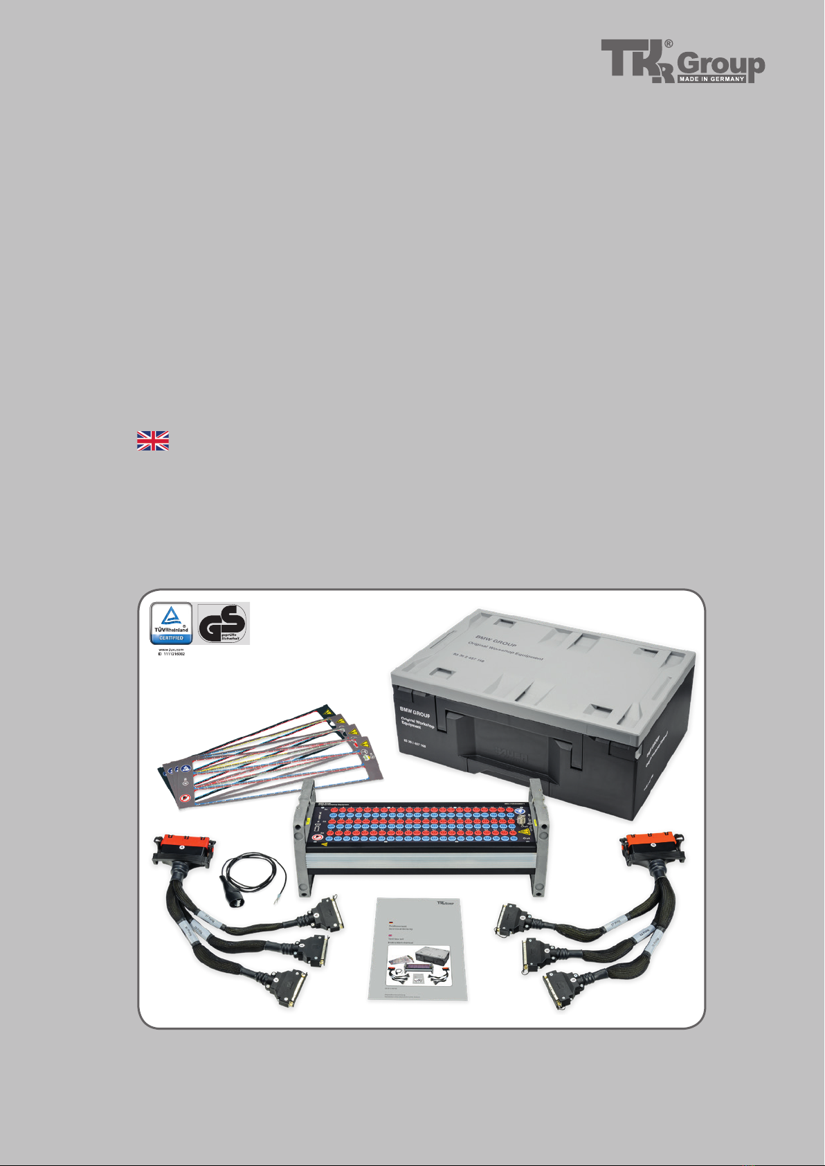
1.3 Delivery contents
83 30 2 299 408
Clip
Red and black
1 pair
Accessories not included:
Test box A/B coding
3-fold adapter A coding
Basic template
3-fold adapter B coding
Test box template for
12 7 241/83 30 0 494 963
Test box template for
61 2 421/83 30 0 494 894
Suitcase test box set BMW
Instruction manual
BMW test box set
Grounding cable
Clip
1x
1x
1x
1x
1x
1x
1x
1x
1x
1x
66
A
A
G
C
C
H
B
B
D
D
E
E
I
1.4.1
1.4.2
B
F
1.4.3
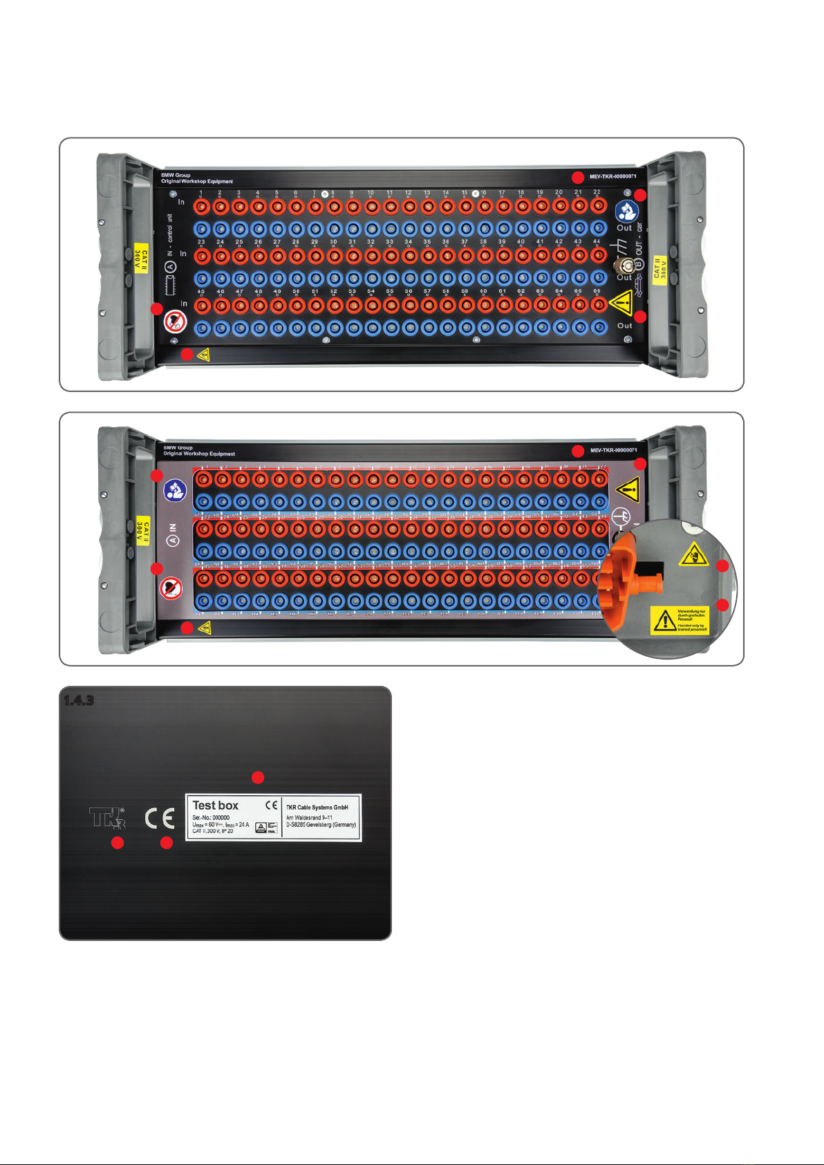
1.4 Labels
Fig. 1.4.1 Test box without template
Fig. 1.4.2 Test box with template and side view
Fig. 1.4.3 Test box floor
A Prohibited for persons with pacemakers
B Warning: Dangerous electrical voltage
C Type number
D Observe the instruction manual!
E Attention! General hazard
F Use only by trained personnel!
G Manufacturer label
H CE label
I Nameplate

77
1.5 Safety instructions
This test box is only approved for the
application intended by the manufacturer.
Only original accessories may be used. There
is a high safety risk if no original tool or
original accessories are used. To determine
which accessories may be used, please refer
to the current repair instructions for the
respective application.
Personnel who have not been trained
or instructed in the use of the device are
prohibited from using it. Ensure that the
instruction manual is made available to the
operating personnel.
The accident prevention regulations valid in
the respective countries must be observed.
Only accessories that are expressly approved
for the respective application may be used.
Never throw or drop the test box. Never
misuse the test box.
The test box may only be used at ambient
temperatures
above 5 °C and up to a
maximum of 45 °C.
Never use the test box in potentially
explosive areas.
Check all components for damage
before each use. In case of defects or
abnormalities, the test box may not be
used. Contact the manufacturer‘s service.

88
2.1.1
2.1.2
Fig. 2.1.1
Test box
Rated voltage: 60 V⎓
Rated current at any 2 connection
points:
24 A
Measurement category: CAT II 300 V
Weight: 6.00 kg
Length: 450 mm
Width: 172 mm
Height: 165 mm
Test socket-Ø: 4 mm
2.1 Technical data
Fig. 2.1.1
3-fold adapter cable
Rated voltage: 60 V⎓
Rated current: Imax. 1 A
99
2.2.1
5
7
6
3
4
2
1
2.3 Operating conditions
Climatic conditions
Storage temperature: -40 °C to +80 °C (-40 °F to +176 °F)
Operating temperature: -5 °C to +45 °C (+41 °F to +113 °F)
Ambient humidity: up to 95% (non-condensing)
Protection class: IP20
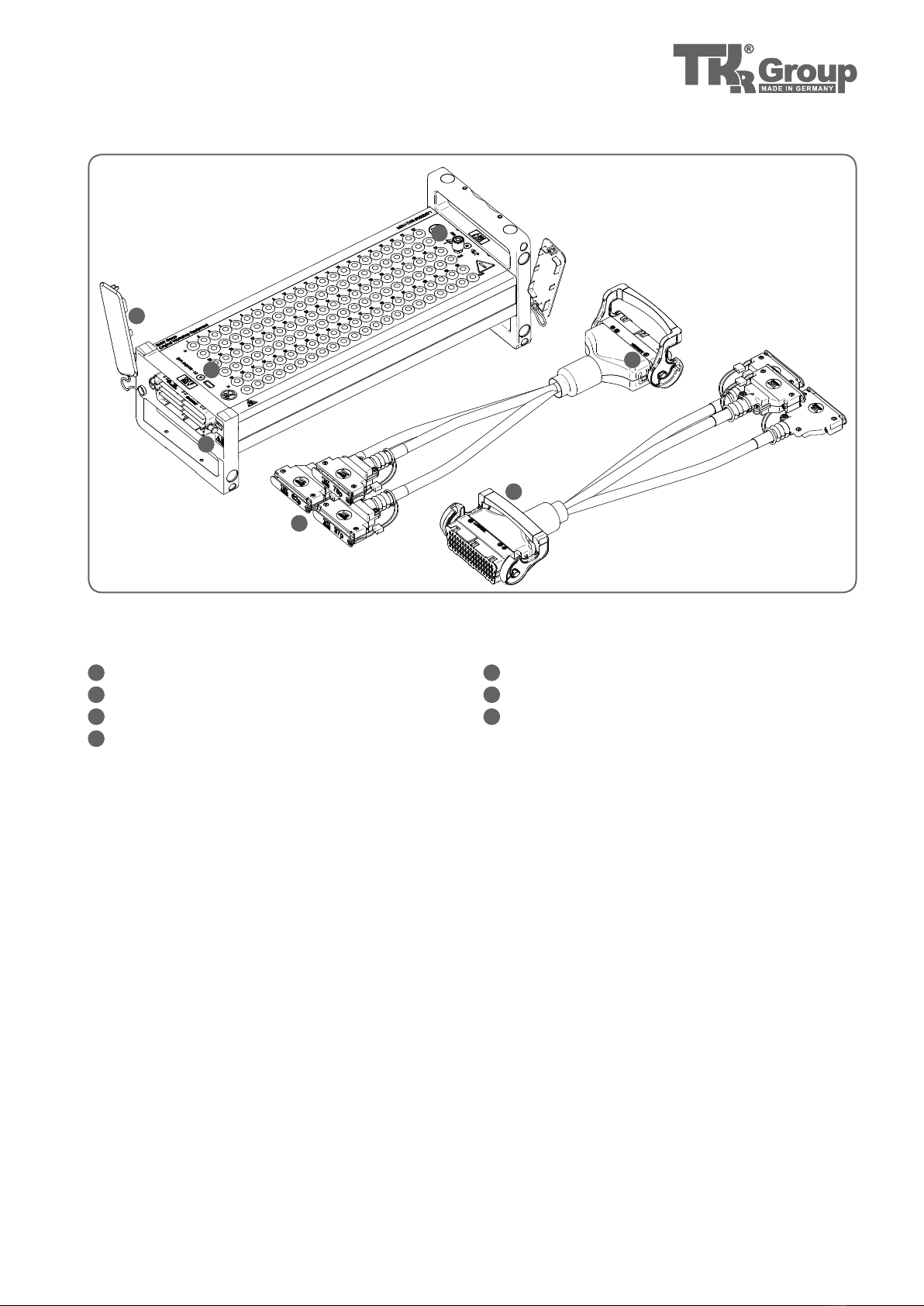
Fig. 2.2.1
Test box with 3-fold adapters
1Ground connection
2Dust cover
3Test box coding specification
43-fold adapter connection
Electromagnetic compatibility (EMC)
DIN EN 61 326 - 1
• Electrical measuring, control, regulating, and
laboratory equipment
EMC requirement - Part 1: General requirements
5D-SUB connector
63-fold adapter coding specification
7Handgriff
2.2 Device components

1010
3.1 Principles for handling the test box
3.2 Intended use
Risk of injury
Please ensure that you and your colleagues handle the test
box correctly. Any misuse or divergent use of the test box
is expressly prohibited. The test box may only be used as
intended.
Lay all cables so that no one can trip over them.
Before beginning work, the test box user must discharge
himself at a suitable ground potential with the gauge in
order to avoid discharge via the test box.
Warranty
The manufacturer assumes no liability for damage resulting
from improper repair or the use of third-party spare parts.
The warranty is void for damage to the device caused by
improper operation.
The test box is used for guided troubleshooting in low-
voltage vehicle on-board power systems in accordance with
diagnostic systems.
The following tests and measurements are possible using
specific adapter cables (shorter than 3 m):
• Measuring potentials against vehicle mass using
a multimeter or other diagnostic equipment
• Testing of potential differences with the help of a
multimeter or other diagnostic equipment
• Measuring resistances between terminals with
the aid of a suitable multimeter or ohmmeter
Surroundings
Make sure that the text box set is used in a working area that
is free from heat sources (max. 45 °C / 113 °F) as well as corro-
sive liquids, fats, and oils.
Declaration of Conformity
The test box set has been tested and manufactured in
accordance with European guidelines. The corresponding
Declaration of Conformity is attached to this instruction
manual.
Qualified personnel
Trained and instructed personnel have specialist training
that enables them to repair/maintain the respective vehi-
cles and vehicle components.
These workers have also demonstrably participated in
training that enables them to do specific tasks with the tool.
Misuse
The supply of currents by means of the 3-fold adapter is
considered misuse and is therefore expressly prohibited.

1111
3.3.1
3.3.2
3.3.3
3.3.4
3.3 Startup - Preparation
Fig. 3.3.1
Remove the dust protection cap on
both sides of the test box.
Fig. 3.3.3, 3.3.4
Determine whether the 3-fold adapter
is properly plugged into the test box.
Lock the 3-fold adapter by pulling
down the handle.
Fig. 3.3.2
Connect the 3-fold adapter according
to the coding on the test box.
1212
3.3.6
3.3.7
3.3.8
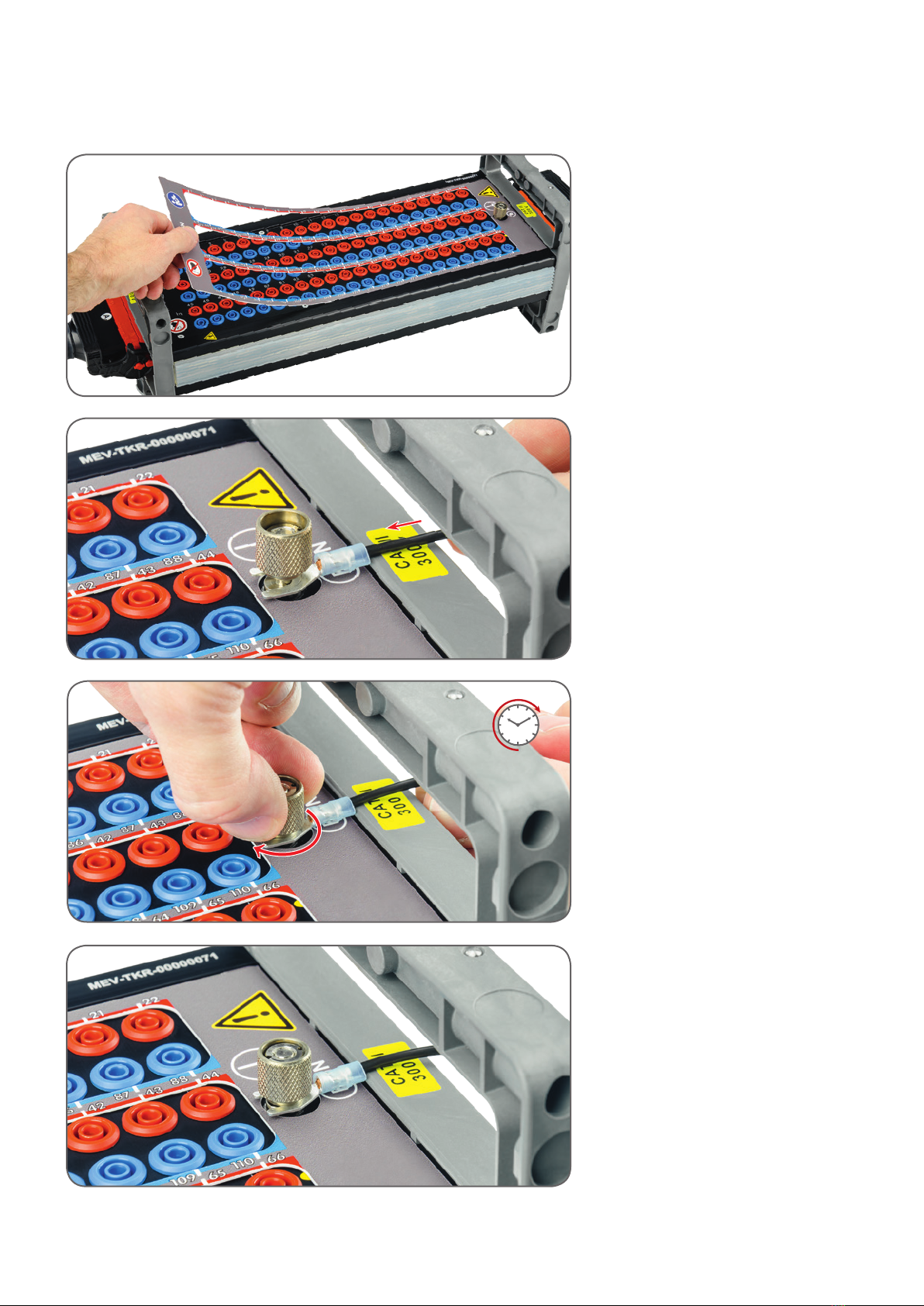
3.3.5 Fig. 3.3.5
Place the template on the test box.
Fig. 3.3.6 to 3.3.8
Connect the ground connection
cable to the test box by connecting
the ground contact as shown in
Fig. 3.3.7, tightening clockwise.
1313
3.4.2
3.4.3
3.4.1
A
B
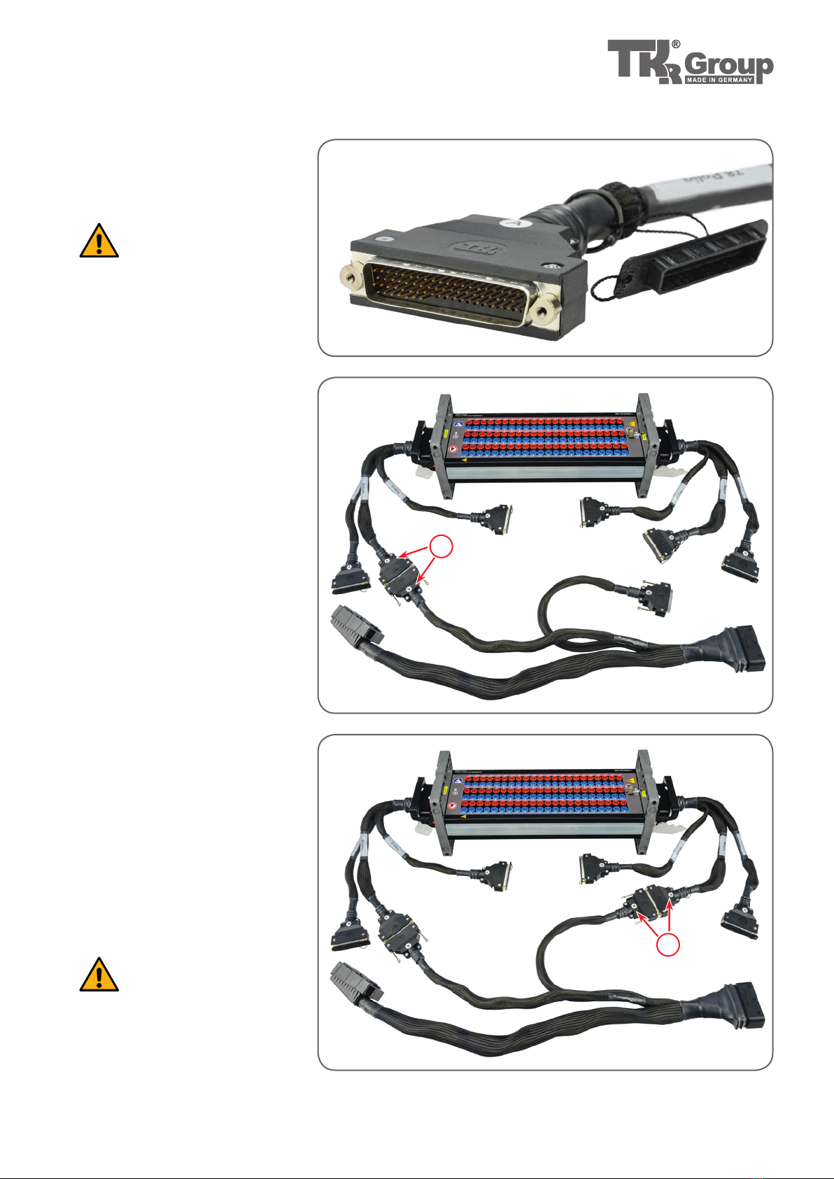
3.4 Connecting the BMW adapter cable
Fig. 3.4.2
Connection of a BMW adapter cable
with a maximum of 66 pins
Connect the BMW adapter cable to
the 3-fold adapter (A coding). Use one
of the three D-SUB connectors (37, 62
or 78 pin).
Fig. 3.4.1
Remove the D-SUB protective cover
before use.
Attention! There is volt-
age at the contacts of
the D-SUB connector! Attach pro-
tective covers to all unused plugs
during and after measurement.
Fig. 3.4.3
Connection of a BMW adapter cable
with a maximum of 132 pins
For cables with more than 66 pins, the
second 3-fold adapter (B coding) must
also be used. Connect the second
D-SUB plug of the cable here. As a
result, the other pins of the cable (up
to a maximum of 132) will be connect-
ed to the test box.
Short circuit hazard!
Never use more than one
connector on the 3-fold adapter!
The vehicle electronics can other-
wise be severely damaged.

1414
3.5.2
3.5.3
3.5.5
3.5.4
3.5.1
3.5 Connecting the test box to the vehicle
Fig. 3.5.1
Clamp the ground connection cable to the ground pin of
the external jump-starting point (FSSP). Do not connect the
ground connection cable to the positive contact.
Fig. 3.5.2, 3.5.3
Connect the test box to the control unit.
Fig. 3.5.4, 3.5.5
Connect the test box to the vehicle wiring harness.

1515
3.6.1
3.6.2
3.6 Possible applications
To start up the test box,
follow the instructions:
3.3 Startup - Preparation
3.4 Connecting the
BMW adapter cable
3.5 Connecting the
test box to the vehicle
Fig. 3.6.1
Connection to voltage measure-
ment: potentials with regard to
vehicle mass
To measure potentials compared to
the vehicle mass, first close the COM
or ground connection of the gauge
using suitable clamps1) to the ground
contact of the test box. Join the posi-
tive connection of the gauge with the
test box socket to be measured. The
resulting voltage can now be read on
the gauge.
Fig. 3.6.2
Connection to voltage measure-
ment: Potential differences
To measure potential differences,
close the COM or connect the ground
connection of the gauge to the socket
of the test box to be measured using
suitable measuring cables. Then
connect the positive terminal of the
gauge to another socket. Depending
on the potential difference, the pos-
itive or negative potential difference
(voltage) is displayed on the gauge.
1) e.g. items 83 30 2 299 408 from the BMW automotive measuring cable set (83 30 2 299 380)
1616
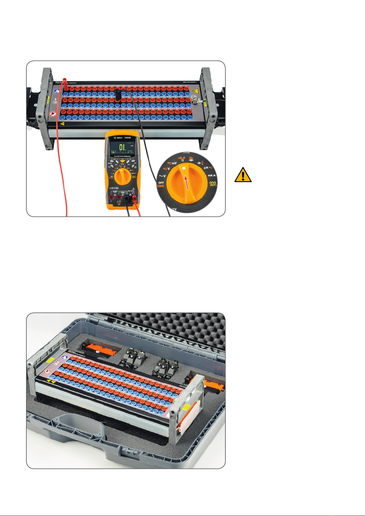
3.6.3
3.7.1
Fig. 3.6.3
Connection to the resistance
measurement
To measure resistance, connect the
COM or connect the ground connec-
tion of the gauge to the socket of the
test box to be measured using suitable
measuring cables. Then connect the
positive terminal
of the gauge to an-
other socket
. The resulting resistance
can now be read on the gauge.
Attention! The gauge
supplies power during
resistance measurement. Resistanc-
es may only be measured in a zero
voltage and zero current state! If
disregarded, there is a high risk
that the gauge will be destroyed
and components damaged.
3.7 Storing the test box
Fig. 3.7.1
To protect the test box against con-
tamination and damage, store the test
box and its accessories in the trans-
port case provided for this purpose.

1717
4.1 Maintenance
4.2 Troubleshooting
Care / Cleaning
If necessary, clean the test box with a dry cloth after use.
Then replace the dust protection caps and place the box in
the carrying case.
Maintenance
The test box is maintenance-free except for occasional
cleaning.
Service address
TKR Cable Systems GmbH
Am Waldesrand 9–11
D-58285 Gevelsberg (Germany)
Malfunction Problem Remedy Chapter
3-fold adapter cannot
be plugged in
3-fold adapter is worn Replacement of the 3-fold
adapter
4.3
3-fold adapter was not inserted
correctly
Determine whether the 3-fold
adapter is properly plugged into
the test box.
3.3
Handle of the 3-fold adapter
cannot be pulled down
3-fold adapter was not inserted
correctly
Determine whether the 3-fold
adapter is properly plugged into
the test box.
3.3
Expected voltage is not displayed
Ground connection cable was
not connected
Connect ground connection cable
3.3
3-fold adapter, ground connec-
tion cable or BMW adapter cable
was not inserted correctly
Check all connections
3.3, 3.4,
3.5, 3.6
Wrong coding (A connected with
B, B with A)
Connect BMW adapter cable and
3-fold adapter according to the
coding (A with A, B with B)
3.4
1818
5.1 Disposal
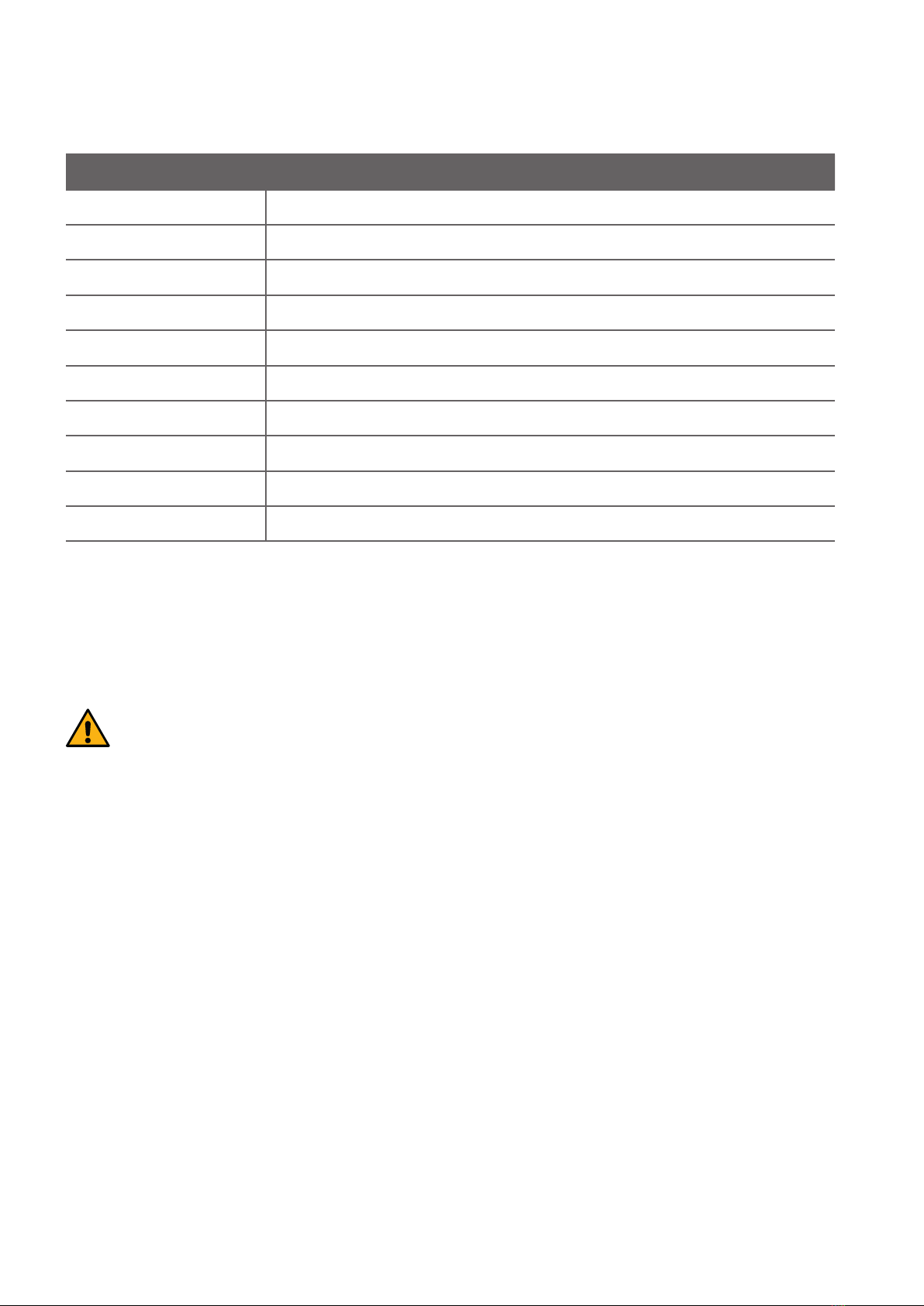
4.3 Spare parts
Devices, machinery, and the components of devices and machinery must be disposed of in accordance
with the laws, regulations and other stipulations of the country in which they are located.
We recommend disposal by licensed specialist companies.
Item number Designation
MEV BMW 00000071 Test box A/B coding
4-01-000000C Grounding cable
DOK-BMW-00000010 BMW test box set instruction manual
77-001111 Basic template 1 - 132 pins
77-001116 Test box template for 12 7 241/83 30 0 494 963
77-001117 Test box template for 61 2 421/83 30 0 494 894
77-001124 Basic template 1 - 120 pins
BGR BMW 10000114 3-fold adapter A coding
BGR BMW 10000115 3-fold adapter B coding
WZK-BMW-0000006 Suitcase test box set BMW

EU Declaration of Conformity
according to the Low Voltage Directive
2014/35/EU
Manufacturer: TKR Cable Systems GmbH
Am Waldesrand 9–11
58285 Gevelsberg, Germany
Person authorised
to compile the technical
documentation: Thorsten Weyland
Tool type: Test box set
Type designation: 83 30 2 457 168
Developed and constructed in
accordance with the standards and
guidelines stated below, by
TKR Cable Systems GmbH
Am Waldesrand 9–11
58285 Gevelsberg (Germany)
Applied harmonised
standards: EN 61010-1 : 2010
Serial number range: 00001–10000
Low voltage directive: 2014/35/EU
As the manufacturer,
we declare: The correspondingly labelled products
fulltherequirementsofthestateddirective
and standards.
Gevelsberg, 20.01.2018 Thorsten Weyland
Technical Manager

Am Waldesrand 9–11
D-58285 Gevelsberg (Germany)
Telephone +49 2332 66607-0
Fax +49 2332 66607-941
Email [email protected]om
Website www.tkrgroup.com
Other languages, accessories and spare parts:
www.tkr-service.com
DOK-BMW-00000010, Rev2 19.02
Table of contents
Other TKR Group Test Equipment manuals


Popular Test Equipment manuals by other brands


vinmetrica
vinmetrica Dissolved Oxygen System user manual

Kyoritsu Electrical Instruments Works, Ltd.
Kyoritsu Electrical Instruments Works, Ltd. KEW3125A instruction manual

Megger
Megger HPG AC Series Operation manual

ATS
ATS 540 Series instruction manual

Desoutter
Desoutter FCT Series manual

BEHA
BEHA UNITEST 93408 instruction manual