TLV LV5 User manual

172-65123MA-05 (LV Series) 23 August 2021
Balanced Pressure Thermostatic Steam Trap
LV5 / LV13 / LV13L / LV13N / LV21
Copyright © 2021 by TLV CO., LTD.
All rights reserved

172-65123MA-05 (LV Series) 23 Aug 2021
1
Contents
Introduction ....................................................................... 1
Safety Considerations....................................................... 2
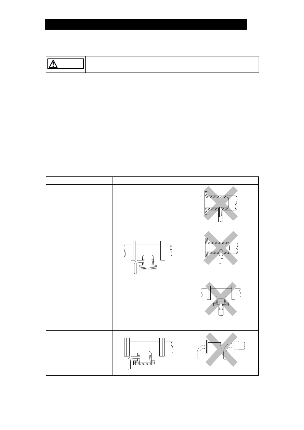
Checking the Piping.......................................................... 4
Specifications.................................................................... 5
Configuration..................................................................... 7
Installation......................................................................... 8
Maintenance...................................................................... 9
Disassembly/Reassembly............................................... 10
Troubleshooting .............................................................. 13
TLV EXPRESS LIMITED WARRANTY........................... 14
Service ............................................................................ 16
Introduction
Thank you for purchasing the TLV balanced pressure thermostatic steam trap.
This product has been thoroughly inspected before being shipped from the factory.
When the product is delivered, before doing anything else, check the specifications
and external appearance to make sure nothing is out of the ordinary. Also be sure to
read this manual carefully before use and follow the instructions to be sure of using
the product properly.
This steam trap is of a revolutionary design that uses a high-performance X-element.
This is a new type of valve mechanism in which a thermoliquid is sealed inside the
X-element and the valve opens or closes based on the difference between the
saturation temperatures of the thermoliquid and the water. The X-element is very
sensitive to changes in temperature, and responds with great accuracy, quickly
discharging air and the large quantities of condensate created immediately after
operation start-up, thereby greatly reducing start-up time. It also reacts with great
sensitivity to the inflow of large quantities of condensate and hot air during operation,
preventing air-locking.
The superior features of the X-element help increase heating efficiency and reduce
manpower requirements for maintenance and bypass blowdown.
If detailed instructions for special order specifications or options not contained in this
manual are required, please contact TLV for full details.
This instruction manual is for the models listed on the front cover. It is needed not
only for installation, but also for subsequent maintenance, disassembly/reassembly
and troubleshooting. Please keep it in a safe place for future reference.

172-65123MA-05 (LV Series) 23 Aug 2021
2
Safety Considerations
Read this section carefully before use and be sure to follow the instructions.
Installation, inspection, maintenance, repairs, disassembly, adjustment and valve
opening/closing should be carried out only by trained maintenance personnel.
The precautions listed in this manual are designed to ensure safety and prevent
equipment damage and personal injury. For situations that may occur as a result
of erroneous handling, three different types of cautionary items are used to
indicate the degree of urgency and the scale of potential damage and danger:
DANGER, WARNING and CAUTION.
The three types of cautionary items above are very important for safety: be sure
to observe all of them as they relate to installation, use, maintenance, and repair.
Furthermore, TLV accepts no responsibility for any accidents or damage
occurring as a result of failure to observe these precautions.
Symbols
Indicates a DANGER, WARNING or CAUTION item.
DANGER
Indicates an urgent situation which poses a threat of death or
serious injury
WARNING
Indicates that there is a potential threat of death or serious injury
CAUTION
Indicates that there is a possibility of injury or equipment/product
damage
CAUTION
Install properly and DO NOT use this product outside the
recommended operating pressure, temperature and other
specification ranges.
Improper use may result in such hazards as damage to the product
or malfunctions that may lead to serious accidents. Local
regulations may restrict the use of this product to below the
conditions quoted.
Take measures to prevent people from coming into direct
contact with product outlets.
Failure to do so may result in burns or other injury from the
discharge of fluids.
When disassembling or removing the product, wait until the
internal pressure equals atmospheric pressure and the surface
of the product has cooled to room temperature.
Disassembling or removing the product when it is hot or under
pressure may lead to discharge of fluids, causing burns, other
injuries or damage.
Be sure to use only the recommended components when
repairing the product, and NEVER attempt to modify the
product in any way.
Failure to observe these precautions may result in damage to the
product and burns or other injury due to malfunction or the
discharge of fluids.
Continued on the next page

172-65123MA-05 (LV Series) 23 Aug 2021
3
CAUTION
Do not use excessive force when connecting threaded pipes to
the product.
Over-tightening may cause breakage leading to fluid discharge,
which may cause burns or other injury.
Use only under conditions in which no freeze-up will occur.
Freezing may damage the product, leading to fluid discharge, which
may cause burns or other injury.
Use only under conditions in which no water hammer will
occur.
The impact of water hammer may damage the product, leading to
fluid discharge, which may cause burns or other injury.

172-65123MA-05 (LV Series) 23 Aug 2021
4
Checking the Piping
CAUTION
Use only under conditions in which no water hammer will occur.
The impact of water hammer may damage the product, leading to fluid
discharge, which may cause burns or other injury.
Check to make sure that the pipes to be connected to the product have been
installed properly.
1. Has the piping work been done correctly, as shown in the figures below?
2. Is the pipe diameter suitable?
3. Has the product been installed with the arrow on the product pointing in the
direction of flow?
4. Has sufficient space been secured for maintenance?
5. Have isolation valves been installed at the inlet and outlet?
6. If the outlet is subject to back pressure, has a check valve (TLV-CK) been
installed?
7. Is the inlet pipe as short as possible, with as few bends as possible, and installed
so the liquid will flow naturally down into the trap?
Requirement
Correct
Incorrect
Install catchpot with the
proper diameter.
Diameter is too small.
Make sure the flow of
condensate is not
obstructed.
Diameter is too small and inlet
protrudes into pipe interior.
To prevent rust and scale
from flowing into the trap,
the inlet pipe should be
connected 25 –50 mm (1 –
2 in) above the base of the
T-pipe.
Rust and scale flow into the trap
with the condensate.
When installing on the blind
end, make sure the flow of
condensate is not
obstructed.
Condensate collects in the pipe.

172-65123MA-05 (LV Series) 23 Aug 2021
5
Specifications
CAUTION
Install properly and DO NOT use this product outside the recommended
operating pressure, temperature and other specification ranges.
Improper use may result in such hazards as damage to the product or
malfunctions that may lead to serious accidents. Local regulations may restrict
the use of this product to below the conditions quoted.
Use only under conditions in which no freeze-up will occur.
Freezing may damage the product, leading to fluid discharge, which may cause
burns or other injury.
Refer to the product nameplate for detailed specifications.
LV13L/LV13N
LV5/LV13/LV21
A
Model
B
Nominal Diameter
C
Valve No.
D
Production Lot No.
E
Maximum Allowable Temperature (TMA)*
F
Maximum Allowable Pressure (PMA)*
G
Maximum Operating Temperature (TMO)
H
Maximum Operating Pressure (PMO)
I
X-element Type
* Maximum allowable pressure (PMA) and maximum allowable temperature (TMA) are PRESSURE
SHELL DESIGN CONDITIONS, NOT OPERATING CONDITIONS.
** Valve No. is displayed for products with options. This item is omitted from the nameplate when there
are no options.

172-65123MA-05 (LV Series) 23 Aug 2021
6
Maximum Operating Temperature (stainless steel models)
LV21
LV5
250
220
200
150
100
(482)
(392)
(302)
(212)
00.5 1.0 1.3 1.5 2.0 2.1
225(437) 235(455)
Saturated Steam Curve
Temp. C (F)
Operating Pressure MPaG (psig)
(75) (150) (185) (215) (300)
(1 MPa = 10.197 kg/cm2)

172-65123MA-05 (LV Series) 23 Aug 2021
7
Configuration
LV5/LV13 (Brass)
LV5/LV21 (Cast Stainless Steel)
LV13L (Brass)
LV13N (Brass)
No.
Part Name
Repair Kit*
1
Body
2
Cover
3
Valve Seat
✓
4
X-element
✓
5
X-element Guide
✓
6
Spring Clip
✓
7
Screen
✓
8
Cover Gasket
✓
9
Nameplate
* For LV13L (brass) and LV13N (brass)

172-65123MA-05 (LV Series) 23 Aug 2021
8
Installation
CAUTION
Install properly and DO NOT use this product outside the recommended
operating pressure, temperature and other specification ranges.
Improper use may result in such hazards as damage to the product or
malfunctions that may lead to serious accidents. Local regulations may restrict
the use of this product to below the conditions quoted.
Do not use excessive force when connecting threaded pipes to the product.
Over-tightening may cause breakage leading to fluid discharge, which may cause
burns or other injury.
Installation, inspection, maintenance, repairs, disassembly, adjustment and valve
opening/closing should be carried out only by trained maintenance personnel.
1. Before installation, be sure to remove all protective seals.
2. Before installing the product, blow out the inlet piping to remove any piping
scraps, dirt and oil. Close the inlet valve after blowdown.
3. Install with the arrow on the product pointing in the direction of flow.
4. LV13L: Install in the piping with the inlet horizontal and the outlet vertical (with the
cover facing upwards).
LV5/LV13/LV21: Can be installed either vertically or horizontally. Make sure the
inlet side is at the top if installed vertically. There may be a slight increase in the
amount of steam leakage if installed horizontally.
LV13N: Horizontal installation is recommended (with the cover facing upwards).
Vertical installation with the inlet side at the top is possible; however there may be
a slight increase in the amount of steam leakage.
5. Install a condensate outlet valve and outlet piping.
6. Open the inlet and outlet valve and check to make sure that the product functions
properly.
If there is a problem, determine the cause using the “Troubleshooting” section in this
manual.

172-65123MA-05 (LV Series) 23 Aug 2021
9
Maintenance
CAUTION
Take measures to prevent people from coming into direct contact with
product outlets.
Failure to do so may result in burns or other injury from the discharge of fluids.
Be sure to use only the recommended components when repairing the
product, and NEVER attempt to modify the product in any way.
Failure to observe these precautions may result in damage to the product and
burns or other injury due to malfunction or the discharge of fluids.
Operational Check
A visual inspection of the following items should be done on a daily basis to
determine whether the product is operating properly or has failed. Periodically (at
least biannually) the operation should also be checked by using diagnostic
equipment, such as a stethoscope, thermometer, TLV Pocket TrapMan or TLV
TrapMan.
If the product should fail, it may cause damage to piping and equipment, resulting in
faulty or low quality products or losses due to steam leakage.
Normal
:
Condensate is discharged intermittently together with flash
steam, and the sound of flow can be heard.
Blocked
(Discharge Impossible)
:
No condensate is discharged. The product is quiet and
makes no noise, and the surface temperature of the product
is low.
Blowing
:
Live steam continually flows from the outlet and there is a
continuous metallic sound.
Steam Leakage
:
Live steam is discharged through the product outlet together
with condensate, accompanied by a high-pitched sound.
(When conducting a visual inspection, flash steam is sometimes mistaken for steam leakage.
For this reason, the use of a steam trap diagnostic instrument [such as TLV TrapMan if
appropriate] in conjunction with the visual inspection is highly recommended.)
Parts Inspection
When parts have been removed, or during periodic inspections, use the following
table to inspect the parts and replace any that are found to be defective.
Procedure
Gasket:
Check for warping or damage
Screen:
Check for clogging or corrosion
X-element:
Check for scratches
Valve seat:
Check for scratches
Body interior:
Check for build-up
Valve:
Check for dirt, oil film, wear or scratches

172-65123MA-05 (LV Series) 23 Aug 2021
10
Disassembly/Reassembly
CAUTION
Be sure to use only the recommended components when repairing the
product, and NEVER attempt to modify the product in any way.
Failure to observe these precautions may result in damage to the product and
burns or other injury due to malfunction or the discharge of fluids.
Use the following procedures to remove components. Use the same procedure in
reverse to reassemble.
(Installation, inspection, maintenance, repairs, disassembly, adjustment and valve
opening/closing should be carried out only by trained maintenance personnel.)
Removing/Reattaching Body (LV5/LV13/LV21)
Part
During Disassembly
During Reassembly
Body 1
Remove with a socket
wrench
Consult the table of tightening torques and tighten
to the proper torque
Removing/Reassembling Parts Inside Cover (LV5/LV13/LV21)
Part
During Disassembly
During Reassembly
Screen 7
Remove without bending
Being careful not to bend it, insert with the right side
up
Spring Clip
6
Remove with needle-nose
pliers
Fit securely into the spring clip slots
X-element
4
Remove from the
X-element guide
Holding the ball on the top of the X-element with
pliers, insert slowly, keeping the X-element level
and making sure it does not catch on the guide
(Figure A)
Cover
Gasket * 8
Remove, being careful not
to damage the gasket
Replace with a new gasket if misshapen or
damaged
* Only for brass LV5 and LV13
Figure A
Table of Tightening Torques (LV5/LV13/LV21)
Part
Size
Torque
Distance Across
Flats
mm
(in)
Nm
(lbfft)
mm
(in)
Body 1/Cover 2 (Brass)
(LV5, LV13)
8 –15
(1/4- 1/2)
80
(59)
27
(11/16)
20, 25
(3/4, 1)
80
(59)
41
(15/8)
Body 1/Cover 2 (Stainless Steel)
(LV5, LV21)
8 –15
(1/4- 1/2)
120
(88)
27
(11/16)
(1 Nm 10 kgcm)
Note: Be sure to coat screw threads with anti-seize only on stainless
steel models of LV5 and LV21

172-65123MA-05 (LV Series) 23 Aug 2021
11
Removing/Reattaching Cover (LV13L/LV13N)
Part
During Disassembly
During Reassembly
Cover 2
Remove with a socket
wrench
Consult the table of tightening torques and tighten
to the proper torque
Cover
Gasket 8
Remove, being careful not
to damage the gasket
Replace with a new gasket if misshapen or
damaged
Removing/Reassembling Parts Inside Body (LV13L/LV13N)
Part
During Disassembly
During Reassembly
Spring Clip
6
Remove with needle-nose
pliers or by hand
Fit securely into the spring clip slots (Figure B)
X-element
4
Grasp the ball on the top of
the X-element with pliers
and remove
Holding the ball on the top of the X-element with
pliers, insert slowly, keeping the X-element level
and making sure it does not catch on the guide
(Figure C)
Valve Seat
3
Remove with a socket
wrench
Consult the table of tightening torques and tighten
to the proper torque
X-element
Guide 5
Remove without bending
Fix with the Valve Seat and make sure the
X-element can be inserted smoothly
Screen 7
Remove without bending
Insert without bending
Figure B
Figure C
Table of Tightening Torques (LV13L/LV13N)
Part
Torque
Distance Across Flats
N∙m
(lbfft)
mm
(in)
Cover 2 (LV13L, LV13N)
80
(59)
32
(11/4)
Valve Seat 3
35
(26)
19
(3/4)
(1 N·m 10 kg·cm)
Note: LV13L/LV13N: DO NOT coat screw threads with anti-seize.

172-65123MA-05 (LV Series) 23 Aug 2021
12
Exploded View
LV5/LV13 LV5/LV21 LV13L LV13N
(Brass) (Stainless Steel)
No.
Part Name
1
Body
2
Cover
3
Valve Seat
4
X-element
5
X-element Guide
6
Spring Clip
7
Screen
8
Cover Gasket

172-65123MA-05 (LV Series) 23 Aug 2021
13
Troubleshooting
CAUTION
When disassembling or removing the product, wait until the internal
pressure equals atmospheric pressure and the surface of the product has
cooled to room temperature.
Disassembling or removing the product when it is hot or under pressure may
lead to discharge of fluids, causing burns, other injuries or damage.
When the product fails to operate properly, use the following table to locate the
cause and remedy.
Problem
Cause
Remedy
No condensate
is discharged
(blocked) or
discharge is
poor
The X-element is sticking to the
valve seat
Clean parts
The valve seat is clogged
Clean or replace with a new valve
seat
The screen is clogged with rust or
scale
Clean parts
The product operating pressure
exceeds the maximum specified
pressure or there is insufficient
pressure differential between the
product inlet and outlet
Compare specifications and actual
operating conditions
Steam is
discharged or
leaks from the
outlet
(blowing)
(steam leakage)
There is rust or scale build-up
between the X-element valve and
valve seat
Clean parts
The X-element valve and/or valve
seat are worn or damaged
Replace with a new X-element
and/or the valve seat/cover
The X-element is broken
Replace with a new X-element
Improper installation
Correct the installation
Trap vibration
Lengthen the inlet piping and fasten
it securely
Steam is
leaking from a
place other
than the outlet
Gasket deterioration or damage
Replace with a new gasket
Improper tightening torques were
used
Tighten to the proper torque
Replace with a new tube fitting
NOTE: When replacing with new, use the parts list for reference and replace with parts from
the repair kit, etc.

172-65123MA-05 (LV Series) 23 Aug 2021
14
TLV EXPRESS LIMITED WARRANTY
Subject to the limitations set forth below, TLV CO., LTD., a Japanese corporation
(“TLV”), warrants that products which are sold by it, TLV International Inc. (“TII”) or one of
its group companies excluding TLV Corporation (a corporation of the United States of
America), (hereinafter the “Products”) are designed and manufactured by TLV, conform
to the specifications published by TLV for the corresponding part numbers (the
“Specifications”) and are free from defective workmanship and materials. The party
from whom the Products were purchased shall be known hereinafter as the “Seller”. With
regard to products or components manufactured by unrelated third parties (the
“Components”), TLV provides no warranty other than the warranty from the third party
manufacturer(s), if any.
Exceptions to Warranty
This warranty does not cover defects or failures caused by:
1. improper shipping, installation, use, handling, etc., by persons other than TLV,
TII or TLV group company personnel, or service representatives authorized by
TLV; or
2. dirt, scale or rust, etc.; or
3. improper disassembly and reassembly, or inadequate inspection and
maintenance by persons other than TLV or TLV group company personnel, or
service representatives authorized by TLV; or
4. disasters or forces of nature or Acts of God; or
5. abuse, abnormal use, accidents or any other cause beyond the control of TLV,
TII or TLV group companies; or
6. improper storage, maintenance or repair; or
7. operation of the Products not in accordance with instructions issued with the
Products or with accepted industry practices; or
8. use for a purpose or in a manner for which the Products were not intended; or
9. use of the Products in a manner inconsistent with the Specifications; or
10. use of the Products with Hazardous Fluids (fluids other than steam, air, water,
nitrogen, carbon dioxide and inert gases (helium, neon, argon, krypton, xenon
and radon)); or
11. failure to follow the instructions contained in the TLV Instruction Manual for the
Product.
Duration of Warranty
This warranty is effective for a period of one (1) year after delivery of Products to the
first end user. Notwithstanding the foregoing, asserting a claim under this warranty
must be brought within three (3) years after the date of delivery to the initial buyer if
not sold initially to the first end user.
ANY IMPLIED WARRANTIES NOT NEGATED HEREBY WHICH MAY ARISE BY
OPERATION OF LAW, INCLUDING THE IMPLIED WARRANTIES OF MERCHANTABILITY
AND FITNESS FOR A PARTICULAR PURPOSE AND ANY EXPRESS WARRANTIES NOT
NEGATED HEREBY, ARE GIVEN SOLELY TO THE INITIAL BUYER AND ARE LIMITED IN
DURATION TO ONE (1) YEAR FROM THE DATE OF SHIPMENT BY THE SELLER.
Exclusive Remedy
THE EXCLUSIVE REMEDY UNDER THIS WARRANTY, UNDER ANY EXPRESS WARRANTY
OR UNDER ANY IMPLIED WARRANTIES NOT NEGATED HEREBY (INCLUDING THE
IMPLIED WARRANTIES OF MERCHANTABILITY AND FITNESS FOR A PARTICULAR
PURPOSE), IS REPLACEMENT; PROVIDED: (a) THE CLAIMED DEFECT IS REPORTED TO

172-65123MA-05 (LV Series) 23 Aug 2021
15
THE SELLER IN WRITING WITHIN THE WARRANTY PERIOD, INCLUDING A DETAILED
WRITTEN DESCRIPTION OF THE CLAIMED DEFECT AND HOW AND WHEN THE
CLAIMED DEFECTIVE PRODUCT WAS USED; AND (b) THE CLAIMED DEFECTIVE
PRODUCT AND A COPY OF THE PURCHASE INVOICE IS RETURNED TO THE SELLER,
FREIGHT AND TRANSPORTATION COSTS PREPAID, UNDER A RETURN MATERIAL
AUTHORIZATION AND TRACKING NUMBER ISSUED BY THE SELLER. ALL LABOR COSTS,
SHIPPING COSTS, AND TRANSPORTATION COSTS ASSOCIATED WITH THE RETURN
OR REPLACEMENT OF THE CLAIMED DEFECTIVE PRODUCT ARE SOLELY THE
RESPONSIBILITY OF BUYER OR THE FIRST END USER. THE SELLER RESERVES THE
RIGHT TO INSPECT ON THE FIRST END USER’S SITE ANY PRODUCTS CLAIMED TO BE
DEFECTIVE BEFORE ISSUING A RETURN MATERIAL AUTHORIZATION. SHOULD SUCH
INSPECTION REVEAL, IN THE SELLER’S REASONABLE DISCRETION, THAT THE
CLAIMED DEFECT IS NOT COVERED BY THIS WARRANTY, THE PARTY ASSERTING THIS
WARRANTY SHALL PAY THE SELLER FOR THE TIME AND EXPENSES RELATED TO
SUCH ON-SITE INSPECTION.
Exclusion of Consequential and Incidental Damages
IT IS SPECIFICALLY ACKNOWLEDGED THAT THIS WARRANTY, ANY OTHER EXPRESS
WARRANTY NOT NEGATED HEREBY, AND ANY IMPLIED WARRANTY NOT NEGATED
HEREBY, INCLUDING THE IMPLIED WARRANTIES OF MERCHANTABILITY AND FITNESS
FOR A PARTICULAR PURPOSE, DO NOT COVER, AND NEITHER TLV, TII NOR ITS TLV
GROUP COMPANIES WILL IN ANY EVENT BE LIABLE FOR, INCIDENTAL OR
CONSEQUENTIAL DAMAGES, INCLUDING, BUT NOT LIMITED TO LOST PROFITS, THE
COST OF DISASSEMBLY AND SHIPMENT OF THE DEFECTIVE PRODUCT, INJURY TO
OTHER PROPERTY, DAMAGE TO BUYER’S OR THE FIRST END USER’S PRODUCT,
DAMAGE TO BUYER’S OR THE FIRST END USER’S PROCESSES, LOSS OF USE, OR
OTHER COMMERCIAL LOSSES. WHERE, DUE TO OPERATION OF LAW,
CONSEQUENTIAL AND INCIDENTAL DAMAGES UNDER THIS WARRANTY, UNDER ANY
OTHER EXPRESS WARRANTY NOT NEGATED HEREBY OR UNDER ANY IMPLIED
WARRANTY NOT NEGATED HEREBY (INCLUDING THE IMPLIED WARRANTIES OF
MERCHANTABILITY AND FITNESS FOR A PARTICULAR PURPOSE) CANNOT BE
EXCLUDED, SUCH DAMAGES ARE EXPRESSLY LIMITED IN AMOUNT TO THE PURCHASE
PRICE OF THE DEFECTIVE PRODUCT. THIS EXCLUSION OF CONSEQUENTIAL AND
INCIDENTAL DAMAGES, AND THE PROVISION OF THIS WARRANTY LIMITING REMEDIES
HEREUNDER TO REPLACEMENT, ARE INDEPENDENT PROVISIONS, AND ANY
DETERMINATION THAT THE LIMITATION OF REMEDIES FAILS OF ITS ESSENTIAL
PURPOSE OR ANY OTHER DETERMINATION THAT EITHER OF THE ABOVE REMEDIES IS
UNENFORCEABLE, SHALL NOT BE CONSTRUED TO MAKE THE OTHER PROVISIONS
UNENFORCEABLE.
Exclusion of Other Warranties
THIS WARRANTY IS IN LIEU OF ALL OTHER WARRANTIES, EXPRESS OR IMPLIED,
AND ALL OTHER WARRANTIES, INCLUDING BUT NOT LIMITED TO THE IMPLIED
WARRANTIES OF MERCHANTABILITY AND FITNESS FOR A PARTICULAR PURPOSE,
ARE EXPRESSLY DISCLAIMED.
Severability
Any provision of this warranty which is invalid, prohibited or unenforceable in any
jurisdiction shall, as to such jurisdiction, be ineffective to the extent of such invalidity,
prohibition or unenforceability without invalidating the remaining provisions hereof,
and any such invalidity, prohibition or unenforceability in any such jurisdiction shall
not invalidate or render unenforceable such provision in any other jurisdiction.

172-65123MA-05 (LV Series) 23 Aug 2021
16
Service
For Serviceor Technical Assistance: Contact your TLV representative or your regional TLV office.
In Europe:
Daimler-Benz-Straße 16-18, 74915 Waibstadt, Germany
Tel:
Fax:
[49]-(0)7263-9150-0
[49]-(0)7263-9150-50
Units 7 & 8, Furlong Business Park, Bishops Cleeve, Gloucestershire GL52
8TW, U.K.
Tel:
Fax:
[44]-(0)1242-227223
[44]-(0)1242-223077
Parc d’Ariane 2, bât. C, 290 rue Ferdinand Perrier, 69800 Saint Priest,
France
Tel:
Fax:
33–(0)4-72482222
[33]-(0)4-72482220
In North America:
13901 South Lakes Drive, Charlotte, NC 28273-6790, U.S.A.
Tel:
Fax:
[1]-704-597-9070
[1]-704-583-1610
In Mexico and Latin America:
Av. Jesús del Monte 39-B-1001, Col. Hda. de las Palmas, Huixquilucan,
Edo. de México, 52763, Mexico
Tel:
Fax:
[52]-55-5359-7949
[52]-55-5359-7585
In Oceania:
Unit 8, 137-145 Rooks Road, Nunawading, Victoria 3131, Australia
Tel:
Fax:
[61]-(0)3-9873 5610
[61]-(0)3-9873 5010
In East Asia:
36 Kaki Bukit Place, #02-01/02, Singapore 416214
Tel:
Fax:
[65]-6747 4600
[65]-6742 0345
Room 5406, No. 103 Cao Bao Road, Shanghai, China 200233
Tel:
Fax:
[86]-(0)21-6482-8622
[86]-(0)21-6482-8623
No.16, Jalan MJ14, Taman Industri Meranti Jaya, 47120 Puchong,
Selangor, Malaysia
Tel:
Fax:
[60]-3-8065-2928
[60]-3-8065-2923
252/94 (K-L) 17th Floor, Muang Thai-Phatra Complex Tower B,
Rachadaphisek Road, Huaykwang, Bangkok 10310, Thailand
Tel:
Fax:
[66]-2-693-3799
[66]-2-693-3979
#302-1 Bundang Technopark B, 723 Pangyo-ro, Bundang, Seongnam,
Gyeonggi, 13511, Korea
Tel:
Fax:
[82]-(0)31-726-2105
[82]-(0)31-726-2195
In the Middle East:
Building2W,No.M002,POBox371684,Dubai AirportFree Zone, Dubai,UAE
Email:
sales-m[email protected]
In Other Countries:
881 Nagasuna, Noguchi, Kakogawa, Hyogo 675-8511, Japan
Tel:
Fax:
[81]-(0)79-427-1818
[81]-(0)79-425-1167
Manufacturer:
881 Nagasuna, Noguchi, Kakogawa, Hyogo 675-8511, Japan
Tel:
Fax:
[81]-(0)79-422-1122
[81]-(0)79-422-0112
Other manuals for LV5
1
This manual suits for next models
4
Table of contents
Other TLV Plumbing Product manuals
Popular Plumbing Product manuals by other brands

Hans Grohe
Hans Grohe Talis M54 270 1jet 72859 Series Instructions for use/assembly instructions

clage
clage ZIP HYDROTAP G4 BC 100/75 Operating and installation instructions

Hans Grohe
Hans Grohe Focus Series Instructions for use/assembly instructions

KitchenAid
KitchenAid KSU90C0M Dimension Guide

Hans Grohe
Hans Grohe Logis 190 71090000 Instructions for use/assembly instructions

Fir Italia
Fir Italia FirUnico SYNERGY OPEN 93 93.1020.8 manual