manuals.online logo
Brands
  1. Home
  2. •
  3. Brands
  4. •
  5. FLOJET
  6. •
  7. Water Pump
  8. •
  9. FLOJET 18555-000 User manual

FLOJET 18555-000 User manual

FEATURES
• Connects directly to the RV waste outlet
• Eliminates 3" (75 mm) sewer hose
• Garden hose discharge port
• Fresh water rinse capabilities
• Remote handheld on/off switch with
6' (1.8 m) wire harness and fuse
• Ability to dump longer distances
• Ability to drain holding tanks at home
• Easy clean up and storage
• Rugged portable storage case
• USCG and CSA listed
SPECIFICATIONS
Pump: Self-Priming Flexible mpeller with
Stainless Steel Wearplate
Impeller: Jabsco Nitrile Compound
Macerator: Stainless Steel Cutter reduces particle
size to 1/8" (4 mm) maximum
Seal: Lip Type
Ports: nlet – 3" (75 mm) RV Connector
Outlet – Garden Hose – see table
Motor: 12 Vdc Permanent Magnet Type,
Fully Enclosed, with Stainless Steel Shaft
Intermitent Duty Only
Weight: 6 lb (2.8 kg)
Case Size: 12" x 13" x 5.5"
(300 mm x 315 mm x 140 mm)
This pump should be used in accordance with EPA
Sanitation Regulations.
Model 18555-000
PORTABLE RV WASTE PUMP
SELF-PRIMING MACERATOR
Hose Size Maximum Hose Length
5/8” (16 mm) 25 feet (7.5m) max
3/4” (19 mm) 50 feet (15m) max
RECOMMENDED HOSE TABLE
APPLICATION
The Flojet 18555-000 DC portable waste pump is the
ideal solution for emptying holding tanks on recreational
vehicles and avoiding dump stations. The macerator
section grinds waste down to a particle size of
1/8" maximum so it can easily be pumped through a
garden hose. Empties a typical 40-gallon holding tank in
less than 5 minutes. Do not run more than 15
minutes continuously.
The 18555-series waste pump will macerate and pump
all waste and tissue normally found in recreational
vehicle waste systems. T W LL NOT HANDLE HARD
SOL D OBJECTS, SAN TARY NAPK NS OR RAGS.
Recommended lengths are based on horizontal
discharge. Longer discharge runs create higher
resistance and may result in the pump motor over
heating.
DO NOT MOUNT PERMANENTLY
TO THE RV WASTE PORT.
DO NOT RUN DRY
FOR MORE
THAN 30 SECONDS.
Fuse
(20 amp)
Orange (+)
Orange (+)
Butt Connectors
Orange (+) Black (-)
Black (-) Black (-)
Orange (+)
Discharge Port Adapter
(Garden Hose Connection)
Water Inlet
ON / OFF Valve
(Garden Hose Connection)
Power
Source
Rubber Boot
WIRING DIAGRAM
1. Remove end cap from drain pipe.
2. nstall portable waste pump on drain in any
convenient position, twisting clockwise to lock.
Be sure that o-ring is on pump adapter prior to
installing unit.
3. nstall waste/garden hose on discharge port
adapter.
4. nstall rinse water hose to on-off valve.
5. Open black water valve, turn on pump.
6. Turn off pump and open gray water valve. Let gray
water backflush black water tank. Turn on pump.
7. Turn off pump, open rinsing valve and back fill
tanks for rinsing. Turn on pump. Turn off rinse
water. Drain tanks.
8. Close both drain valves, turn on rinse water (40 PS
max.) and pump. Rinse pump and discharge hose.
9. Turn off water and pump, disconnect hose and
pump. Store until next use.
10. Replace end cap on drain pipe.
OPERATING INSTRUCTIONS
IMPELLER RELEASE FEATURE
After long periods of
non-use, a stuck impeller
can be easily broken loose
with a screwdriver inserted in
motor shaft slot. Remove
rubber boot, turn shaft
clockwise as shown, and
replace rubber boot.
ELECTRICAL INSTRUCTIONS
1. Refer to electrical drawing above. Connect the 6 foot
switch assembly to RV waste pump motor wires with
butt connectors (connect the orange motor wire to
the orange switch wire; and the black motor wire to
the black connector wire).
2. Locate a 12 VDC, 20 amp power source and install
the 6 foot power connector-cable; Connect the
orange positive wire to a 20 amp circuit, and the
Black negative wire to a negative circuit or chassis
ground. Locate this connector in the waste
compartment or adjacent to the 3 inch waste drain
and valves. Optionally, alligator clips (with 20 amp
rating) may be installed on the 6 foot power
connector-cable for a fully portable installation.
3. Fuse Replacement: The fuse is located under the
black dust cover on the bottom of the On/Off Control
Handle. Use an automotive 20 amp fuse for
replacement.
RECOMMENDED WIRE & FUSE SIZE
Wire Size for Connection
Length etween Battery & Motor
Voltage 1 - 10’ 10 - 20’ Fuse/Breaker
12 12 AWG 10 AWG 20 amp
11
22
33
4
4
6677
88
99
1010
1111
1212 1313
1414
1515
55
1717
1616
EXPLODED VIEW
DISASSEMBLY
Remove the four acorn nuts 3/8” (10 mm) (Key 1) and
fiber washers (Key 2) from the pump studs (Key 3). Slide
the macerator adapter (Key 4) off the studs. nsert a thin
bladed 9/32" (7mm) ignition wrench behind the chopper
plate (Key 6) and onto the flat of the motor shaft to
prevent it from turning. Unscrew (counter-clockwise) the
locknut 7/16” (11 mm) on the end of the motor shaft and
remove the stainless steel chopper blade.†Remove the
pump wearplate (Key 7) and two paper gaskets (Key 8).
Now slide the pump body (Key 12) with impeller (Key 9),
small wearplate (Key 10), two studs and shaft seal as an
assembly off the motor shaft and remaining two
mounting studs. Remove the starlock retaining washer
on the seal and push the seal out of the seal bore.
f reconditioning pump with a service kit (Part No.
18598-1000), it is not necessary to remove the seal
because the new seal is pre-installed in the new body. t
is also generally not necessary to remove the slinger or
brass studs screwed into the motor end bell.
ASSEMBLY
f installing a new seal, push it into the seal bore of the
body with the lip pointing toward the impeller bore.
Press the starlock washer into the seal bore with the
concave side up to secure the seal in the bore. nstall the
two shorter studs in the two holes with threaded inserts
in the new pump body and tighten finger tight. f
required, screw the two longer studs into the tapped
holes in the motor end bell. Slide the new pump body
with the shaft seal installed onto the motor shaft and two
long mounting studs in the motor. Slide the small
wearplate over the motor shaft and position it in the
bottom of the impeller bore. Slide the new impeller onto
the motor shaft and, with a counter-clockwise motion,
push it into the pump impeller bore. Position one new
gasket on the studs and against the pump body
assuring the cut-out aligns with the inlet groove in the
body. Position the large wearplate and second gasket on
the studs and against the body again aligning the hole in
the wearplate and gasket cut-out with the pump inlet.
Position the chopper on the end of the motor shaft with
drive tab aligned with flat of shaft and pointing toward
the motor. Hold the shaft with the ignition wrench and
secure the chopper to the shaft with the locknut.
position the macerator housing on the four studs
ensuring the cut-out in the inner wall aligns with pump
body inlet port and hole in the wearplate. Position a new
fiber washer on each of the studs and secure the
macerator housing in place with the four acorn nuts.
PARTS LIST
Key
*These parts are supplied in 18598-2000 service kit
Description Qty Part
Number
Acorn Nut
Fiber Washer
Stud
Pump Adapter
Rinse Adapter
Chopper Plate w/Locknut
Wearplate, Large
Gaskets (2 ea. per kit)
mpeller
Wearplate, Small
Pump Body
Seal
Slinger
Stud
Motor
Service Kit
Adapter O-ring Kit (2 per kit)
Rubber Boot
Switch (not shown)
Wire Harness w/Connector
4
4
2
1
1
1
1
1
1
1
1
1
1
2
1
1
1
1
1
1
91085-0340*
91613-0140*
17288-0010*
18599-000A*
91010250A*
37056-1000*
18597-1000*
18596-1000*
6303-0003*
12316-1002*
18593-1001*
1040-0000*
6342-0000 *
17288-0000*
74001-1853A*
18598-2000*
91010253A*
21000371
21000378
20030415A
1
2
3
4
5
6
7
8
9
10
11
12
13
14
15
16
17
Copyright 2007, TT Corporation Printed in U.S.A. All Rights Reserved Form: 81000-373 Rev. E 08/2007
ONE YEAR LIMITED WARRANTY
A. LIMITED ARRANTY: Flojet warrants that at the time of shipment,
the products manufactured by Flojet and sold hereunder shall be in
conformity with applicable written specifications and descriptions referred
to or set forth herein, free from defects in material and workmanship,
merchantable, and suitable for a particular purpose, provided such is
implied by State law under the circumstances of this sale.
B. ARRANTY ADJUSTMENT
1. Flojet agrees to repair or furnish a replacement for, but not to
remove or install, any product or component thereof which, within
one (1) year from date of purchase, shall upon test and examination
by Flojet prove defective within the above warranty. Receipt
verifying purchase date is required to obtain adjustment.
2. Buyer shall notify Flojet of any defect within this warranty no later
than ninety (90) days after the defect is discovered.
3. NO PRODUCT ILL BE ACCEPTED FOR RETURN OR
REPLACEMENT ITHOUT THE PRIOR RITTEN
AUTHORIZATION OF FLOJET. Upon such authorization, and in
accordance with instructions from Flojet, the product will be returned
to Flojet, shipping charges prepaid by Buyer. Request shipping
address from Flojet customer service. Repair or replacement made
under this warranty will be shipped prepaid to Buyer.
C. EXCLUSIONS FROM ARRANTY AND LIMITATION OF
LIABILITY:
1. The warranty is limited solely as set forth herein and applies only
for the period designated above.
2. FLOJET SHALL NOT BE L ABLE FOR ANY LOSS, DAMAGE,
SPEC AL OR CONSEQUENT AL DAMAGE OF ANY K ND,
WHETHER BASED UPON WARRANTY, CONTRACT,
NEGL GENCE, OR STR CT L AB L TY AR S NG N CONNECT ON
W TH THE SALE, USE, OR REPA R OF THE PRODUCT.
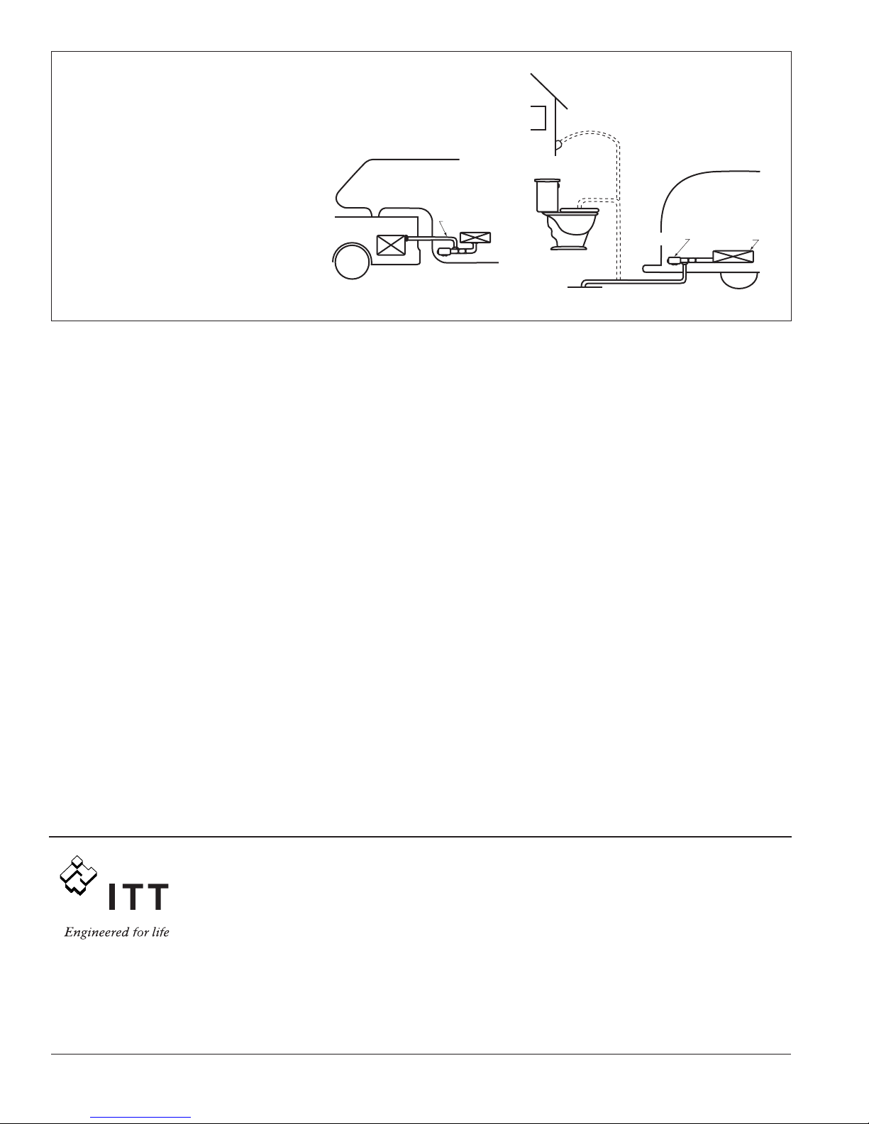
FROM HOLDINGTANK TO
AUXILIARYTANK
Home Sewer Access
Toilet Bowl
Dum p Station
18555 000 Holding Tank
Sewer Drain
HOLDING TANK PUMP OUT
Garden Hose
Garden Hose
EASY TO USE
The waste pump can be used to
empty the holding tank into any
convenient sewer receiver such as a
sewer clean-out at your home.
APPLICATIONS
• Empty holding tanks and avoid
dump stations
• Transfer waste from holding tank to
auxiliary tank
3. THE MAX MUM L AB L TY OF FLOJET N CONNECT ON W TH
TH S WARRANTY SHALL NOT N ANY CASE EXCEED THE
CONTRACT PR CE FOR THE PRODUCT CLA MED TO BE
DEFECT VE OR UNSU TABLE.
4. This warranty does not extend to any product manufactured by
Flojet which has been subjected to misuse, neglect, accident,
improper installation, or use in violation of instructions furnished
by Flojet.
5. This warranty does not extend to or apply to any unit which has
been repaired or altered at any place other than Flojet’s factory, or
by persons not expressly approved by Flojet, nor to any unit the
serial number, model number, or identification of which has been
removed, defaced or changed.
6. Components manufactured by any supplier other than Flojet shall
bear only that warranty made by the manufacturer of that product.
7. This warranty applies to products defined as “consumer products”
by the Consumer Product Warranties Act as from time to time
amended.
D. CONSUMER RIGHTS: This warranty gives you specific legal
rights, and you may have other rights which vary from state to
state. Some states do not allow exclusion or limitation odamages.
STANDARD ARRANTY: f the products manufactured and sold
hereunder are not Consumer Products, the warranty extended to
Buyer shall be as set forth in subparagraphs (A), (B), and (C),
EXCEPT THAT ALL EXPRESS OR IMPLIED ARRANTIES OR
MERCHANTABILITY OR SUITABILITY FOR ANY PARTICULAR
PURPOSE ARE EXCLUDED.
www.flojet.com
THE PRODUCTS DESCR BED HERE N ARE
SUBJECT TO THE STANDARD FLOJET ONE YEAR
L M TED WARRANTY, WH CH S AVA LABLE FOR
YOUR NSPECT ON UPON REQUEST.
U.S.A.
Flojet
666 E. Dyer Rd.
Santa Ana, CA 92705
Phone: 714.557.4700
Fax: 714.628.8478
UN TED K NGDOM
Flojet
Bingley Road, Hoddesdon
Hertfordshire EN11 OBU
Tel: +44 (0) 1992 450145
Fax: +44 (0) 1992 467132
CANADA
Fluid Products Canada
55 Royal Road
Guelph, Ontario N1H 1T1
Tel: 519 821.1900
Fax: 519 821.2569
JAPAN
NHK Jabsco Company Ltd.
3-21-10, Shin-Yokohama
Kohoku-Ku, Yokohama, 222
Tel: 045.475.8906
Fax: 045.475.8908
GERMANY
Jabsco GmbH
Oststrasse 28
22840 Norderstedt
Tel: +49-40-53 53 73 -0
Fax: +49-40-53 53 73 -11
TALY
Jabsco Marine talia
Via Tommaseo, 6
20059 Vimercate, Milano
Tel: +39 039 685 2323
Fax: +39 039 666 307

Other FLOJET Water Pump manuals

FLOJET G56 User manual

FLOJET

FLOJET G56 User manual

FLOJET 4300 Series User manual

FLOJET

FLOJET 4300 Series User manual

FLOJET N5100-010 Guide

FLOJET

FLOJET N5100-010 Guide

FLOJET quad II diaphragm 4125 series User manual

FLOJET

FLOJET quad II diaphragm 4125 series User manual

FLOJET 2100-12 User manual

FLOJET

FLOJET 2100-12 User manual

FLOJET N5000 Series Operation manual

FLOJET

FLOJET N5000 Series Operation manual

FLOJET G257 Series Guide

FLOJET

FLOJET G257 Series Guide

FLOJET G-57 Series Installation instructions

FLOJET

FLOJET G-57 Series Installation instructions

FLOJET R3526144 User manual

FLOJET

FLOJET R3526144 User manual

FLOJET R3B21 Series User manual

FLOJET

FLOJET R3B21 Series User manual

FLOJET 4105 Series User manual

FLOJET

FLOJET 4105 Series User manual

FLOJET 3426 series User manual

FLOJET

FLOJET 3426 series User manual

FLOJET N5000 User manual

FLOJET

FLOJET N5000 User manual

FLOJET 03526-144 User manual

FLOJET

FLOJET 03526-144 User manual

FLOJET N5100 Series Guide

FLOJET

FLOJET N5100 Series Guide

FLOJET 02840100A Operating and installation instructions

FLOJET

FLOJET 02840100A Operating and installation instructions

FLOJET 4305-144 User manual

FLOJET

FLOJET 4305-144 User manual

FLOJET R4515-743 User manual

FLOJET

FLOJET R4515-743 User manual

FLOJET G573 User manual

FLOJET

FLOJET G573 User manual

FLOJET BevJet Compact User manual

FLOJET

FLOJET BevJet Compact User manual

FLOJET 4325 Series User manual

FLOJET

FLOJET 4325 Series User manual

FLOJET G70C Series Owner's manual

FLOJET

FLOJET G70C Series Owner's manual

FLOJET 2125 Series User manual

FLOJET

FLOJET 2125 Series User manual

FLOJET Triplex Diaphragm 3426 Series User manual

FLOJET

FLOJET Triplex Diaphragm 3426 Series User manual

Popular Water Pump manuals by other brands

IWAKI PUMPS EWN-R instruction manual

IWAKI PUMPS

IWAKI PUMPS EWN-R instruction manual

Reefe RainPro RM5000 Installation Guide & Owners Information

Reefe

Reefe RainPro RM5000 Installation Guide & Owners Information

BUSCH R 5 series instruction manual

BUSCH

BUSCH R 5 series instruction manual

Einhell Royal GP JET 1300 NIRO operating instructions

Einhell Royal

Einhell Royal GP JET 1300 NIRO operating instructions

Varian 969-9365 Series instruction manual

Varian

Varian 969-9365 Series instruction manual

BADU Eco Touch II manual

BADU

BADU Eco Touch II manual

Cosmo CSPGU25 Technical information for installation and operation

Cosmo

Cosmo CSPGU25 Technical information for installation and operation

JABSCO 18590 Series manual

JABSCO

JABSCO 18590 Series manual

Tuxhorn tubra-PGS 01 Assembly and operating instructions

Tuxhorn

Tuxhorn tubra-PGS 01 Assembly and operating instructions

Oase AquaMax Eco Premium 6000 operating instructions

Oase

Oase AquaMax Eco Premium 6000 operating instructions

Dionex UltiMate 3000 Series operating instructions

Dionex

Dionex UltiMate 3000 Series operating instructions

Biral A 802 Installation and operating instructions

Biral

Biral A 802 Installation and operating instructions

CAT Pumps 7CP6110CS Service manual

CAT Pumps

CAT Pumps 7CP6110CS Service manual

Wetelux 82 06 93 instruction manual

Wetelux

Wetelux 82 06 93 instruction manual

Ariston SOLARcomfort Instructions for installation and servicing

Ariston

Ariston SOLARcomfort Instructions for installation and servicing

Grundfos DMX 227 Installation and operating instructions

Grundfos

Grundfos DMX 227 Installation and operating instructions

SKF ETP-924 Series owner's manual

SKF

SKF ETP-924 Series owner's manual

Trillium FLOWAY Instructions manual for installation, operation and maintenance

Trillium

Trillium FLOWAY Instructions manual for installation, operation and maintenance

manuals.online logo
manuals.online logoBrands
  • About & Mission
  • Contact us
  • Privacy Policy
  • Terms and Conditions

Copyright 2025 Manuals.Online. All Rights Reserved.