TMC EPIC EV4500 Quick start guide

EV4500
ET4300
810-ECA
800-EFM
Technical Guide
for Installation and
Maintenance
Please read before using telephone.

2
Getting Started
Technical Guide for Installation and Maintenance
What is the Epic System?
The Epic System is a 4-Line 16 Station Intercom Speakerphone with Caller ID
that provides small businesses with tremendous capabilities that, until now,
have only been available in larger, complex systems costing much more.
The Epic System is very easy to install, there’s no complicated wiring or central
controller unit; the brains are built into each phone. Simply plug the phones into
your wall outlets and jacks and your ready to go!

3
Getting Started
Important note – The advanced features of this telephone work by sending a data or inter-
com signal over Line 1.
Important Notes on DSL:
The micro filters that may have been provided by the DSL provider to prevent interference
with telephones are NOT compatible with these Epic telephones, since these same filters will
also block the data signals of the system from traveling between the phones.
DSL Installation Option A:
(preferred method)
The solution is to have a DSL data splitter installed at your network interface/D-Mark point.
This way there will be one unfiltered line going directly to your DSL modem, and there will be
one DSL filter with the entire Epic system behind this filter.
DSL Installation Option B:
If you are a current DSL customer and your DSL service is provided over line 1 you have the
option of reversing the line cords in all telephones, this will move the DSL service over to line
three of the telephone sets. This will prevent the DSL from interfering with the advanced fea-
tures of the Epic phone system.

4
Getting Started
Important note – The structured wiring for the Epic System can either be “Daisy Chained”
(Fig. 1 below), or “Homerun” (Fig. 2 below).
We recommend using “Twisted Pair” cable whenever possible.
The total cumulative length of cabling in the installation should not exceed 1000 feet.
Fig. 1. Daisy Chain Wiring – All phones are wired together into a single loop.
Getting Started
Public Switched
Telephone Network
(PSTN)
Public Switched
Telephone Network
(PSTN)
Punch block
Fig. 2. Star Wiring Configuration – each phone jack is independently wired to the
central point.

5
Installing Your System
In order for you to properly connect your EPIC System to an existing wiring system, it is im-
portant that you understand its configuration.
The following are the most common multiple line situations. They consist of either one or
both types of standard telephone jacks: The RJ11 Single Line Jack and the RJ14 Double Line
Jack. Your system should match one of them.
2 incoming lines with
1 wall jack
2 incoming lines with
2 wall jacks
3 incoming lines with
2 wall jacks
3 incoming lines with
3 wall jacks
4 incoming lines with
2 wall jacks
4 incoming lines with
3 wall jacks
4 incoming lines with
4 wall jacks
Installing Your System

6
Installing Your System
Up to 16 Epic System telephones may be connected to form your office/home configuration.
Each phone must be assigned a different station number, from 11 to 26.
Important note – Each Epic System telephone must be connected to the same Line 1 tele-
phone number for proper operation. The remaining lines may or may not be connected to
each station as you desire.
Standard Installation:
Your Epic telephones come factory-set for a standard “Shared” installation, which is also
called “square” in telephone terminology. This means that Line 1 is to be connected to the
same Line 1 telephone number at all the stations. Line 2 is to be connected to the same Line
2 telephone number at all the stations, and so on for Lines 3 and 4.
This is the desired setup for most installations, and if this is how you will be connecting
your Epic System, you do not need to change any of the line connection settings in the tele-
phones. You need only connect the phones to the telephone lines, and then follow the in-
structions on page 9 to be sure that you have connected the telephone numbers in the same
order to each station.
Installations with Private Lines, Auxiliary Lines, and Unconnected Lines:
You may wish to connect private lines to Lines 2, 3 or 4 at some or all of your tele-
different telephone number than the corresponding line at the other stations. These sort of
installation requirements are common in Centrex environments, or in companies where clus-
ters of telephones share common lines. In addition you may wish to leave some lines uncon-
nected at some stations.
If your installation has any of these requirements, carefully fill out the worksheet on the follow-
ing page and use it as a guide as you connect the telephone lines to your Epic telephones.
Mark each line at each station as Shared, Private, Aux or Unconnected.
Refer to the following page “Setting Up Private, Auxiliary and Unconnected Lines” if you are
not sure of the meaning of these terms.

7
Note that line 1 must be “Shared” at all stations, meaning that Line 1 must be connected to the
same telephone number at all stations.
Station
Number
User’s Name or
Telephone Location
Line 1
Tel #
Line 2
Tel #
Line 3
Tel #
Line 4
Tel #
dera
hS
et
av
irP
1x
uA
2L
d
etc
e
n
n
ocnU
dera
h
S
et
av
irP
1xu
A
3
L
de
t
c
enno
c
n
U
dera
hS
et
avi
rP
1x
uA
4L
2x
uA
4L
d
etc
e
n
n
ocnU
Stn. 11 Shared
Stn. 12 Shared
Stn. 13 Shared
Stn. 14 Shared
Stn. 15 Shared
Stn. 16 Shared
Stn. 17 Shared
Stn. 18 Shared
Stn. 19 Shared
Stn. 20 Shared
Stn. 21 Shared
Stn. 22 Shared
Stn. 23 Shared
Stn. 24 Shared
Stn. 25 Shared
Stn. 26 Shared
Stn. 27 Shared
Stn. 28 Shared
Installing Your System
Installation Worksheet

8
Important note – If you have circled anything other than “Shared” on the worksheet, you
must follow the instructions below to set each phone as you have marked on the worksheet.
Setting Up Private, Auxiliary and Unconnected Lines
To program:
1. Press PROGRAM.
The display will read “Program...”
2. Press the soft key under NEXT
repeatedly, until “Line Connections”
appears In the display, and then
press ENTER.
The display will show the current
line connection setting for Line 2.
3. Press the soft key under CHANGE
repeatedly, until the desired line
connection setting for Line 2 is dis-
played.
The choices are:
L2: SHARED (factory setting)
L2: PRIVATE
L2: L2 AUX1
L2: UNCONNECTED
4. Press the soft key under NEXT to
see the current setting for Line 3,
and repeat steps 3 and 4 to change
the settings for Lines 3-4.
5. Press PROGRAM to exit.
While you must share the same Line 1 telephone num-
ber at all the stations, you may choose to leave some
lines unconnected at particular stations or to connect
private or AUX1liary lines to Lines 2, 3 or 4 at particular
stations.
SHARED: This is the factory setting for all lines, and is
the setting you use if the particular line is connected at
this station to the same telephone number as the cor-
responding line at the other stations.
PRIVATE: Use this setting at any telephone that is con-
nected to a different telephone number than the cor-
responding line at the other stations. For example, you
may connect your private telephone number to Line 3
at your station instead of connecting your station to the
shared Line 3. In this example, you would set Line 3 at
your station as PRIVATE.
AUX: Use this setting if two or more stations are con-
nected to a different telephone number than the cor-
responding line at the other stations, but they share the
same number among them- selves. For example, you
may connect a group of stations to a separate Line 3
telephone number than the rest of the system, yet they
share that same Line 3 telephone number among them-
selves. In this example, you would set Line 3 at these
stations to “L3 AUX1.”
Note that you can have up to one auxiliary Line 2, one
auxiliary Line 3, and up to two auxiliary Line 4’s.
UNCONNECTED: Use this feature at any telephone that
is not physically connected to all of its lines. For ex-
ample, you may install an EPIC 4- line telephone in a
room that is currently wired for only lines 1, 2 and 3.
In this example, you would set Line 4 at this station as
UNCONNECTED.
Installing Your System

9
Install Desk/Table Top Phone
1. Connect First Line Cord
Connect one end of a long telephone
line cord to the jack on the bottom of the
telephone labeled L1/L2.
Connect the other end directly to the wall
jack labeled lines 1 & 2.
2. Connect Second Line Cord
Connect one end of a long telephone line
cord to the jack on the back of the tele-
phone labeled L3/L4.
Connect the other end to the wall jack(s)
labeled Lines 3 & 4 in the same manner
as described In the previous step.
3. Connect Handset
Plug either end of the coiled handset
cord into the handset and the other end
into the jack on the side of the telephone.
Place the handset in the cradle.
4. Connect Power Cord
Plug the AC power cord into the adapter
jack on the bottom of the telephone.
Thread the power cord into the recessed
groove.
Plug the AC adapter into an electrical
outlet not controlled by a wall switch.
Installing Your System
10
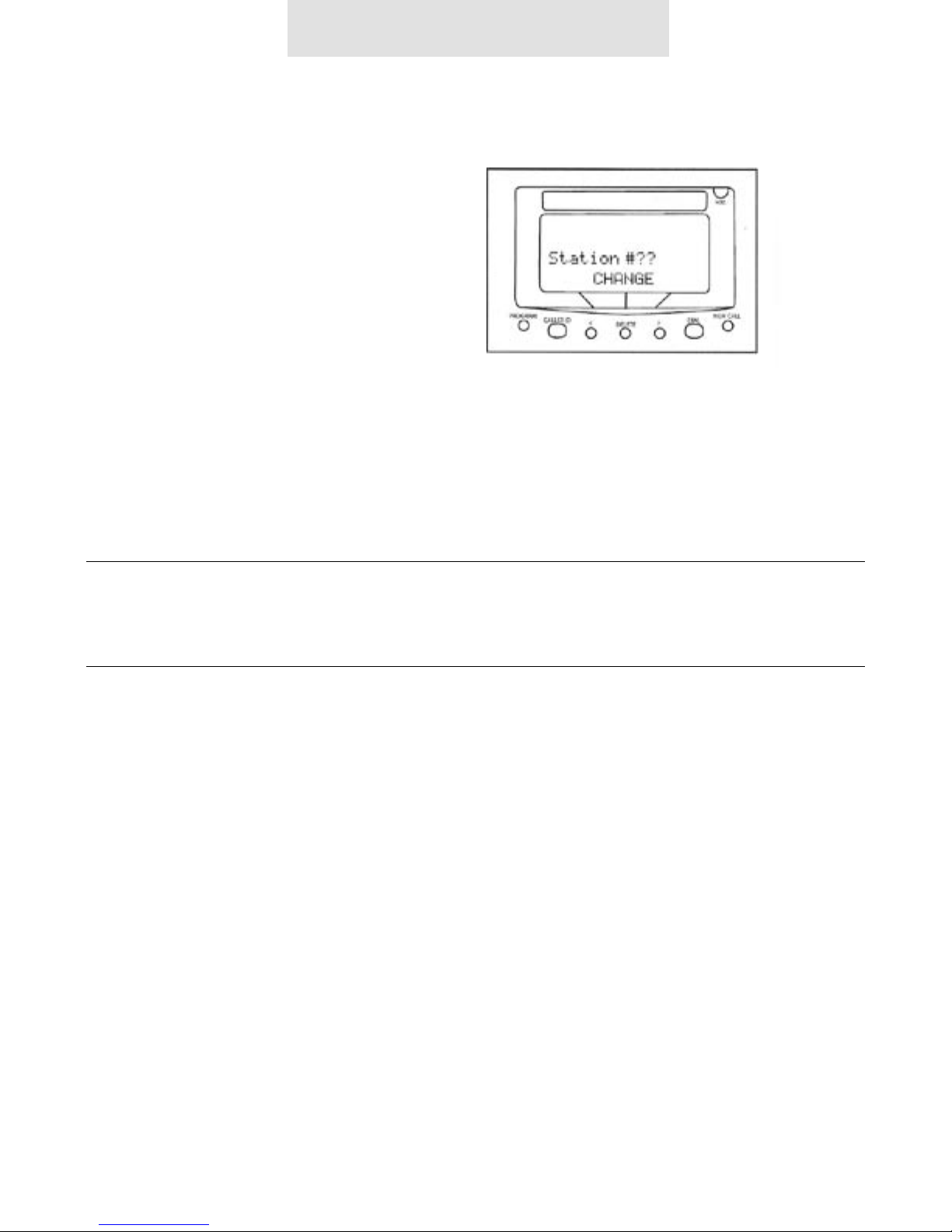
Assigning Station Number
To program:
1. Press PROGRAM.
The display will read “Program...”
2. Press the soft key under NEXT.
The display will show the currently
assigned station number.
3. Press the soft key under CHANGE
repeatedly, until the desired station
number is displayed.
The choices are Station #11 through
Station #26
4. Press PROGRAM to exit.
Until a telephone is assigned a station number, the
telephone will not operate, The choices are Station #1
through and the display will read “station #7?. Station
#26 To assign this telephone a station number, simply
press the soft key under CHANGE 4 Press PROGRAM
to exit repeatedly until the desired station number is
displayed.
Verifying Proper Installation
First, verify that line 1 is connected to
the same telephone number at all the
telephones.
1. Press the line 1 button at one of the
telephones. The line 1 LED should be
green, the speakerphone LED should be
red, and dial tone should be heard from
the speaker.
2. Now go to each of the other stations and
make sure that each line 1 LED is red.
Next, make sure that lines 2, 3 and 4 are
connected the same at all the phones
by following the following steps at each
telephone:
1. Press the line 1 button. The line 1 LED
should be green, the speakerphone LED
should be red, and dial tone should be
heard from the speaker.
2. Dial the telephone number for line 2.
The line 2 LED should flash slowly. If the
line 2 LED does not flash, then line 2 is
improperly connected to this telephone.
3. If this telephone utilizes line 3 and/or line
4, repeat steps 1 and 2, substituting the
respective phone numbers in step 2.
Installing Your System
Important note – The “soft keys” referenced above, are located under the LCD display.
These are the “< DELETE >” buttons. The functionality of these buttons will change
depending on the instruction written above the button in the LCD.
For example, in the above illustration “CHANGE = the “DELETE” button.

11
1. Verify proper installation
See Page 9 of the “ET4300 User Guide”
for instructions.
2. Reset the phone
See “Instructions for resetting the
ET4300 telephone” below.
3. Move the unit
To another working area to find out if the
problem remains at the original location,
or if the problem follows the telephone
set to the new location.
4. Change the part
Replace the AC transformer if the phone
does not power up. Change the handset
& cord if there are audio problems such
as static or no audio on the handset
itself.
Troubleshooting
Troubleshooting
Important note – The following troubleshooting techniques are mandatory to effectively troubleshoot
the Epic system. These steps should be performed in the order listed below.

12
Please keep in mind that these telephones
and feature modules communicate with one
another over the internal line one wiring. They
share data and are able to intercom one an-
other using RF (radio frequency signals). Keep-
ing this in mind, any incompatible equipment
such as a DSL micro filter or any other brand
multi-line telephone set connected to line one
can cause a wide range of problems. Please
remember to keep line one void of any third
party device if possible.
Important note – System wide problems are
most likely caused by one particular phone,
feature module or other incompatible device
connected to the system.
I cannot over emphasize the importance of
verifying proper installation, resetting and re-
initializing the phone system when problems
arise.
If you suspect any telephone, feature mod-
ule or other piece of equipment to be causing
problems disconnect it, and recheck the sys-
tem. If your problem persists you might need
to disconnect one phone at a time (process of
elimination) to find the malfunctioning unit.
It might also to be helpful to disconnect all the
phones and accessories first, and then start by
adding one unit at a time (the process of addi-
tion) testing the operation of the system each
time you add, or remove a phone or module
from service.
Once the malfunctioning unit is isolated, it is
important to completely power it down (re-
member to remove the battery if one is in-
stalled) then unplug the AC adapter from the
phone. You should always reset the unit by
reinitializing the software after the unit is pow-
ered back up. I cannot over emphasize the im-
portance of verifying proper installation, reset-
ting and reinitializing the phone system when
problems arise.
Instructions for resetting the ET4300
telephone:
1. Remove the battery from your phone and
please leave it out.
(Please note: a battery is not necessary
for normal operation.)
2. Unplug the AC adapter from your phone
(power cord).
3. Wait 30 seconds.
4. Re-connect the AC adapter, and wait for
10 seconds.
5. Press the program button once and re-
lease it.
6. Press the headset button twice, and re-
lease it.
7. Dial 2503 on the dial pad and wait for 30
seconds.
8. At this point the display will read “Station
Change??” and all of the line buttons will
flash red.
9. Press the “Delete” button once and re-
lease it, then press the “Program” button
once and release it. This completes the
re-booting procedure.
Notes on SYSTEM WIDE problems:
Troubleshooting

13
1. Is line one the same on all phones?
In order for the ET4300 to work correctly
it is mandatory that line one be the same
on all phones and feature modules.
2. Is this a new installation?
It would be helpful to determine (if pos-
sible) what type of cabling is being uti-
lized and how many telephones / lines
are connected.
3. Was the system ever working
properly?
If so, when did things stop working?
4. What changed prior to the system
failing?
Try to establish the point in time when
the system failed, does this correspond
with something being disconnected or
added to the system.
5. Is there any other brand of equipment
installed on the phone lines?
Try to determine if there are any incom-
patible devices connected to the shared
phone lines. Have the customer remove
all third party equipment from the phone
line prior to troubleshooting further.
6. Is there DSL installed?
The DSL micro filter is not compatible
with the ET4300. Line one must remain
un-filtered for the phone system to oper-
ate normally.
7. Have you disconnected or moved any
of the equipment?
If the system was functioning normally
and then failed after disconnecting one
or more phones or feature modules…
resetting and verifying proper installation
should correct the issue.
8. Are you using all the supplied parts
that came with the unit?
It is very important that all the sup-
plied parts are used… especially the AC
adapter and line cords.
9. Was there a power outage?
If the phones have experienced a power
outage, and the system is malfunction-
ing, reset the system. Please be sure to
remove the battery prior to resetting the
phone. After resetting the phone install
fresh alkaline batteries. Please note: The
alkaline batteries should be renewed
every three months to ensure trouble free
operation.
10. Is it happening on Speaker as well as
Handset?
If the customer is experiencing bad audio
on the handset (buzzing, static etc.) have
them try using the speakerphone and see
if the problem persists. If the problem
goes away, replace the handset, (with
one that works properly) to determine if
the original handset is malfunctioning.
TMC will replace the bad handset for the
customer.
Top Ten Questions to ask when troubleshooting
Troubleshooting

14
One or More Lines Not Working Are they using the supplied line cords?
Are the line cords securely plugged into the line cord inputs (not the
“Data Fax” jack)?
Remember the wall bracket must be removed to access these connec-
tion points on the telephone set.
Are the line cords secured into the wall jacks as well?
Is the problem happening on more than one phone?
Method 1 – If you suspect any telephone, telephone accessory i.e.
(splitters, couplers, modular duplex jacks) or feature module to be
causing “system wide” problems disconnect it, and check the remain-
ing phones in the system.
Method 2 – It might also to be helpful to disconnect all the phones and
accessories first, and then start by adding one unit at a time testing
the operation of the system each time you add, or remove a phone or
module from service.
Are there any phones installed that are working properly on all four
lines?
Solution – If so you can use this working location to test the non-work-
ing telephone to verify its operation at this working location.
Reset the phone (see resetting procedure for your particular model).
Possible issue – The programming allows you to set lines 2, 3 and 4 as
unconnected; this setting may be incorrect and has turned the line off
on the problem phone.
Static First determine if the static is isolated to one phone or if it is system
wide (see notes on system wide problems).
Is the static happening on one or more lines?
(If the equipment is causing static, most likely it will appear on all lines)
Is the static happening on speaker as well as handset?
If the problem is on handset only… the handset may need to be re-
placed.
Solution – Test the phone using a handset from another phone.
Troubleshooting Guide for the ET4300

15
No Dial Tone Is there a station # assigned to the phone?
(See information above “One or More Lines Not Working”)
Possible Bad Handset?
Solution – Try replacing the handset with one that works.
Is the handset incorrectly plugged into the Data/Fax jack?
Solution – The handset input is on the LEFT side of the telephone, the
Data/Fax jack is on the right.
Interference. * The source of most interference i.e. Crosstalk, Radio Frequency Inter-
ference, Dropping Intercom calls, is due to using improper line cords
i.e. 25’ non twisted pair.
Solution – TMC offers 25’ twisted pair line cords.
Incompatible devices such as DSL filters, other brand KSU-less phones
can also cause problems.
Solution – Have a DSL data splitter installed at your network interface/
D-Mark point. This way there will be one unfiltered line going directly to
your DSL modem, and there will be one DSL filter with the entire Epic
system behind this filter.
Phones will not release hold. Programming the phone will allow you to set lines 2, 3 & 4 as Shared,
Private, Unconnected or Aux1/2. If these setting are incorrect i.e. (set-
ting a shared line as private) the phone system will disregard the hold
status of the “private” line and will not release hold on the other set’s in
the system.
Solution – Check the “Line Connection” settings and set them accord-
ingly.
Verify proper installation. (See user guide for your particular model
phone).
Please note: Resetting the phones will help with this problem, but
please be sure to reset “line Connections” for any phones that do in
fact have private or Aux. line groupings.
Troubleshooting Guide for the ET4300

16
Phones are not communicating with
each other
Not able to Intercom between
Stations, display reads:
(“Not Present”).
Please Note: These multi-line intercom speakerphones network with
each another over the line one wiring; if line one is not the same on
all phones they will not communicate with each other. A problem I
encounter quite often is that the line cords are simply switched in the
telephone or feature module i.e. Lines one and two plugged into 3/4
input, and Lines three and four plugged into the 1/2 input.
Solution – Verify proper installation. (See user guide for your particular
model phone).
Another common problem is that a DSL micro filter may be installed.
These micro filters are not compatible with these multi line intercom
speakerphones. These filters need to be removed in order for the tele-
phones to communicate with one another.
Solution - The solution is to have a DSL data splitter installed at your
network interface/D-Mark point. This way there will be one unfiltered
line going directly to your DSL modem, and there will be one DSL filter
with the entire Epic system behind this filter.
The station number was changed or simply does not exist.
Solution - Verify station assignment.
Phone keeps losing the station
assignment, keeps reverting back
to “Station Change ??” with all line
LED’s flashing continuously.
The software provides the ability to lock the station assignment so this
will not continue to happen. The settings for locking down the station
assignment are found under “Advanced Settings”.
Solution – Simply scroll to “Advanced Settings” press “Enter” then
scroll right until you see “Station Normal”. Press the “Delete” button to
change this setting to “locked”.
Troubleshooting Guide for the ET4300
Other manuals for EPIC EV4500
2
This manual suits for next models
3
Table of contents
Other TMC Telephone manuals


