PAGE 3 of 20
AUTO-DIAL S.M.A.R.T. PHONES Pub. 42004-350E
\\s_eng\gtcproddocs\standard ioms - current release\42004 instr. manuals\42004-350e.doc
02/05
Installation
ATTENTION Installation should be performed by qualified personnel and only in
accordance with the National Electrical Code or applicable local codes.
Safety Guidelines
When installing any GAI-Tronics telephone equipment, please adhere to the following guidelines to
ensure the safety of all personnel:
•Do not install telephone wiring during a lightning storm.
•All telephone models must be properly connected to earth ground to protect personnel and to
minimize the effects of any electrostatic discharge (e.g., lightning). The Model 227-003 and 277-003
Telephones each include a ground terminal. Please note proper grounding does not eliminate the
need for lightning protection for the telephone or the telephone system.
•Install a UL Listed lightning arrestor on any phone installed where the phone or phone cable is at
risk of being exposed to lightning strikes. The lightning arrestor must be installed as close to the
phone as possible to maximize the protection. It must not be installed within the enclosure supplied
with the phone. Please consult our Service Center at 800-492-1212 for further information.
•Do not install telephone jacks in wet locations unless the jack is specifically designed for wet
locations.
•Do not touch uninsulated telephone wires or terminals unless the telephone line has been
disconnected at the network interface.
•The Model 40404-045 Power Supply must be connected to an ac source within 4 feet of the
telephone. The ac source and power supply must be mounted in a dry location, such as a
GAI-Tronics stanchion.
General Installation Guidelines
GAI-Tronics S.M.A.R.T. phones are designed to operate on telephone lines as detailed in the Product
Overview section of this manual. The telephones are designed to operate with one telephone per line. If
telephones are operated in parallel or “party line configuration” you may experience sporadic phone
operation, difficulties with programming, or premature disconnection of calls. Additionally, if special
features, e.g. voice mail, call waiting, etc, are not disabled, the phone may not function.
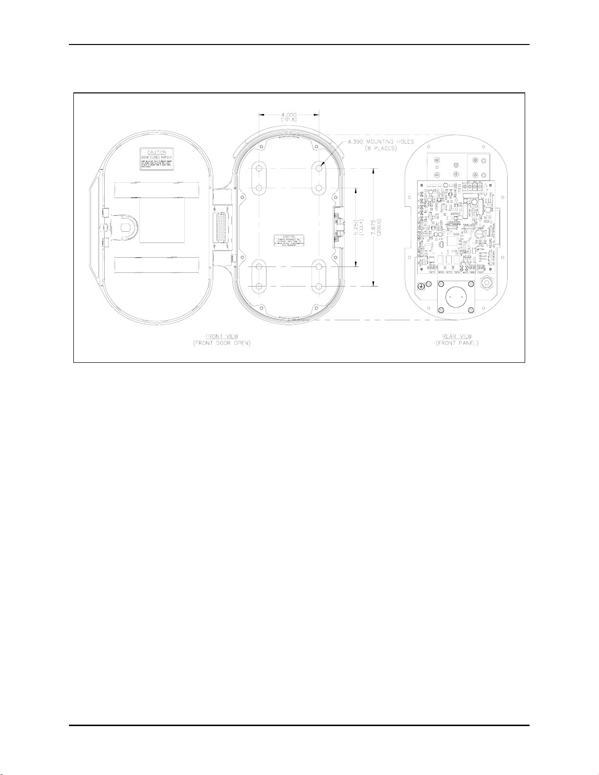
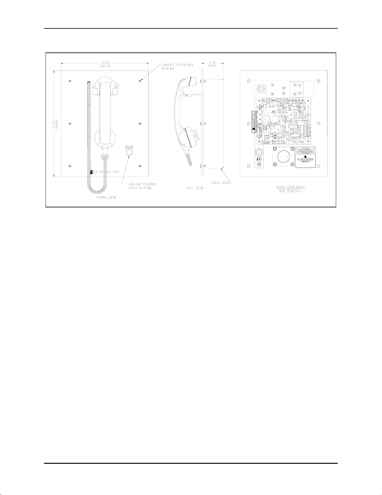
Tamper-Resistant Hardware
All of the telephones described in this manual are vandal resistant. The front panel for each telephone
covered in this manual is attached to its enclosure with tamper-resistant screws. A GAI-Tronics Model
233 Tamper-Resistant Screwdriver (sold separately) is recommended for installing the tamper-resistant
screws.
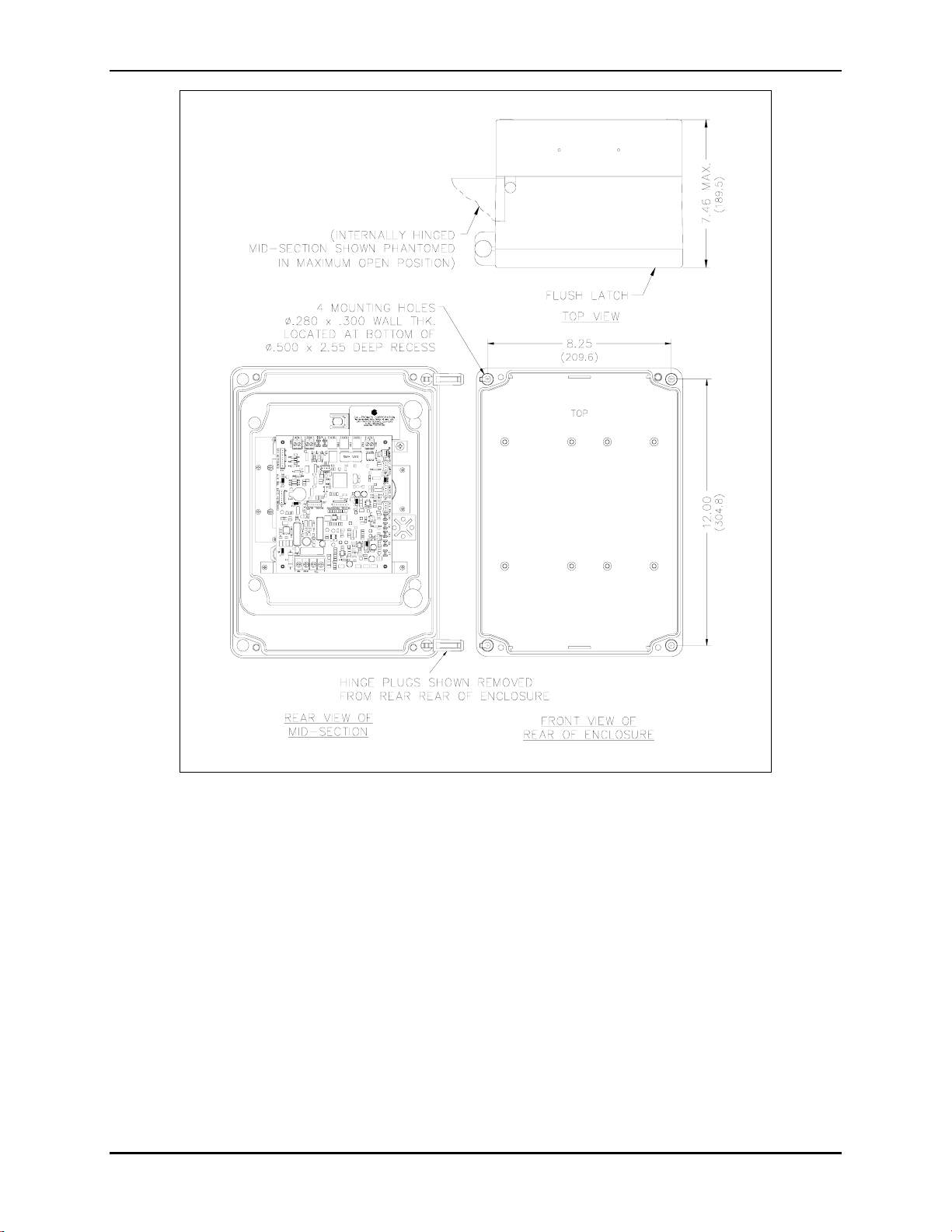
Conduit Installation Details
GAI-Tronics recommends installing telephone lines in conduit to protect against accidental damage and
vandalism. To prevent moisture from entering the enclosure, we strongly recommend the following:
•Conduit should enter the enclosure from the bottom.
•Sealed fittings should be installed at all cable entry points.
•Silicone sealant or equivalent should be applied around and inside all conduit entries.