TMG TMG-HW41T User manual

Hot Water Pressure Washer
4000PSI Hot Water Pressure Washer
MODEL: TMG-HW41T
PRODUCT MANUAL
14HP KOHLER®Powered, 245US Gallon Water Tank
Please read the product manual completely before assembly
Check against the parts list to make sure all parts are received
Wear proper safety goggles or other protective gears while in assembly
Missing parts or questions on assembly?
Please call: 1-877-761-2819 or email: cs@tmgindustrial.com
Do not return the product to dealer, they are not equipped to handle your requests
WWW.TMGINDUSTRIAL.COM Toll Free:1-877-761-2819
V2021.08.31

Table of Contents
IMPORTANT SAFETY INFORMATION.................................................................................................... 3
SPECIFICATIONS....................................................................................................................................... 6
INTRODUCTION......................................................................................................................................... 7
GLOSSARY OF TERMS.............................................................................................................................8
COMPONENT IDENTIFICATION.............................................................................................................. 9
OPERATING INSTRUCTIONS................................................................................................................ 12
CHEMICAL APPLICATION......................................................................................................................15
WINTER PUMP/ COIL PROTECTION................................................................................................... 16
GENERAL MAINTENANCE..................................................................................................................... 16
MAINTENANCE CHECKLIST..................................................................................................................18
QUICK DIAGNOSTICS AND SOLUTIONS GUIDE.............................................................................. 20
SERVICE MANUAL...................................................................................................................................23
WIRING DIAGRAMS.................................................................................................................................34
PARTS DIAGRAMS...................................................................................................................................35
WW W . TM G I ND U ST R IA L .C O M P0 2 /4 1 T oll Fr e e: 1 -8 7 7- 7 61 - 2 81 9

WARNING: To reduce the risk of injury, read
operating instructions carefully before using.
WARNING: Use protective
eyewear and clothing
when operating equipment
in order to avoid personal
injuries.
WARNING: This
machine exceeds
85db. Appropriate
ear protection must
be worn.
WARNING: Risk of
explosion. Operate
only where open flame
or torch is permitted.
WARNING: Flammable liquids
can create fumes which can
ignite, causing property
damage or severe injury.
IMPORTANT SAFETY INFORMATION
The safe operation of our pressure washing systems is the FIRST priority . This will only be achieved by
following the operation and maintenance instructions as explained in this manual and all other enclosed
manuals.
This manual contains essential information regarding the safety hazards, operations, and maintenance
associated with this machine. The manual should always remain with the machine, including if it is resold.
ALL CAUTIONS AND SAFETY WARNINGS MUST BE FOLLOWED TO AVOID INJURY OR DAMAGE TO
EQUIPMENT.
THIS EQUIPMENT IS TO BE USED ONLY BY TRAINED OPERATORS AND MUST ALWAYS BE
ATTENDED DURING OPERATION.
1.Read the instructions in this manual carefully before attempting to
assemble, install, operate or service this pressure washer. Failure to
comply with the instructions could result in personal injury and/or
property damage.
2.Be thoroughly familiar with all controls and know how to stop the
machine in the event of an emergency.
WW W . TM G I ND U ST R IA L .C O M P0 3 /4 1 T oll Fr e e: 1 -8 7 7- 7 61 - 2 81 9

WARNING: Keep water
spray away from electrical
wiring.
4. All electrically powered equipment must be grounded at all times
to prevent fatal electric shots. Do not spray water on or near
electrical components. Do not touch electrical components while
standing in water or when hands are wet. Always make sure
machine is disconnected from power source before servicing.
WARNING: Risk of
injury. Hot surfaces
can cause burns.
WARNING: Hot discharge
fluid. Do not touch or
direct discharge stream at
persons.
WARNING: Risk of fire. Do not add
fuel when operating machine.
3. Never use gasoline, crankcase draining, or waste oil in your
burner fuel tank. Never run pump dry or let the pump run with the
trigger gun released for more than 2 minutes. The minimum
clearance to any combustible material is 12 inches.
.
WARNING: Risk of injection
or severe injury to persons.
Keep clear of nozzle spray.
6. High pressure spray can cause serious injuries. Never point
pressurized spray at any person or animal. Handle the spray
assembly with care.
5. Use equipment in a well-ventilated area to avoid carbon monoxide
poisoning or death. This machine must never be connected to a
Type B gas vent.
WARNING: Risk of asphyxiation.
Use this product only in a well
ventilated area.
WW W . TM G I ND U ST R IA L .C O M P0 4 /4 1 T oll Fr e e: 1 -8 7 7- 7 61 - 2 81 9

WARNING: Risk of injury from
falls when using ladder.
WARNING: Protect from freezing.
WARNING: Risk of Injury
WARNING: Trigger gun kicks
back. Hold with both hands.
7.Hold firmly to the gun and wand during start up and
operation of the machine. Do not attempt to make adjustments
while the trigger gun is in operation.
8.Make sure all quick coupler fittings are properly secured before
operating pressure washer.
9.Do not overreach or stand on anything unstable. Keep a good
balance and make sure to keep a steady footing at all times.
10.It is important to keep your machine from freezing in order to
keep it in its best working condition. Failure to protect your machine
from freezing may cause damage to the machine and personal
injuries may occur as a result.
11.For machines with a 12 V burner: Disconnect battery ground
terminal before servicing.
12.Protect high pressure hoses from sharp objects and
vehicles. Inspect condition of hoses prior to use, or serious
injury could occur.
13.Do not pass acids or other caustic or abrasive fluids through the pump.
RISK OF INJURY
WW W . TM G I ND U ST R IA L .C O M P0 5 /4 1 T oll Fr e e: 1 -8 7 7- 7 61 - 2 81 9

14.Never run pump dry of water or oil or or let the pump
run with the trigger gun released for more than 2
minutes.
15.Do not attempt to operate this machine if fatigued or
under the influence of alcohol, prescription medications,
or drugs.
16.Some of the maintenance procedures involved in this
machine require a certified technician (these steps are
indicated throughout this manual). Do not attempt to
perform these repairs if you are not qualified.
SPECIFICATIONS
Commercial Hot Water Gas - Oil Fired
MODEL
GPM
PSI
BURNER OIL
PRESSURE (PSI)
BTU
HP/ ENGINE
DRIVE
ELECTRIC
START
BURNER
TMG-HW41T
4
4000
130
300,000
14 KOHLER
Direct
Yes
12V
WW W . TM G I ND U ST R IA L .C O M P0 6 /4 1 T oll Fr e e: 1 -8 7 7- 7 61 - 2 81 9

INTRODUCTION
Thank you for selecting a quality product. We are pleased to have you included among the many satisfied
owners of cleaning machines. Years of engineering have gone into the development of these fine
products and only top quality components and materials are used throughout. Each machine is carefully
tested and inspected before leaving our plant to ensure years of dependable performance.
To continue to receive satisfactory performance, remembering that this machine represents a substantial
investment on your part, and if properly cared for and maintained it will return this investment many times
over. As with all mechanical equipment, your machine requires proper operation and maintenance as
outlined in this manual for maximum trouble free life.
This manual has been prepared under the direction of our engineering and service technicians. Their
experience in designing, manufacturing, installing and servicing our equipment from our company’s
inception is condensed in this manual. They know what information the end user needs in order to get the
optimum performance from their pressure washer. Please read carefully.
This manual contains information that will be specific for your pressure washer, as well as similar models.
Carefully review any additional manuals that have been included with your system and follow ALL
ADDITIONAL OPERATING INSTRUCTIONS AND SAFETY NOTICES.
They are specific for the quality components that have been used to manufacture your machine and are
an integral part of the operating and maintenance procedures.
Our goal is that you will be satisfied with the performance, quality, and service you receive and that if you
need to replace this machine in years to come, you will give us the opportunity to continue supplying
equipment to your company.
PLEASE READ MANUALS CAREFULLY BEFORE USING MACHINE. EXAMINE MACHINE AND CRATE
CAREFULLY FOR SHIPPING DAMAGE OR MISSING PARTS. REPORT PROMPTLY ANY SHORTAGES
OR DAMAGE CLAIMS TO FREIGHT CARRIER OR DEALER.
WW W . TM G I ND U ST R IA L .C O M P0 7 /4 1 T oll Fr e e: 1 -8 7 7- 7 61 - 2 81 9

GLOSSARY OF TERMS
PSI – Pounds per square inch. Pressure washers are designed and rated to operate at a specific PSI.
Operating at pressures exceeding the maximum rating could result in damage to the unit and/or
SEVERE PERSONAL INJURY.
GPM – Gallons per minute. The orifice on the pressure wand assembly has been selected to deliver
up to the maximum GPM for your machine.
PRESSURE WAND ASSEMBLY – This refers to the gun, wand, and nozzle.
PUMP – The pump moves the water through the system and delivers it to the pressure wand
assembly.
UNLOADER VALVE – Is a valve located at the head of the pump for unloading water back into the
bypass when the trigger gun is shut off. It also reduces the load on pump when gun is off.
OIL, PUMP – The oil used within the pump to lubricate its operation. Important to use only SAE
15W/40 Non Detergent in the pump (see diagram).
OIL, GASOLINE ENGINE – Gasoline Engines need appropriate lubricant. Use SAE10W/30 detergent
oil.
BURNER – The burner heats the water in hot water pressure washers. It is located under the coil and
may be powered by furnace oil or diesel fuel.
MAXIMUM WORKING PRESSURE The water heater coils are designed to operate safely at normal
working pressure. Each machine is equipped with a safety pressure relief valve which prevents over
pressurization of the high pressure system. It is an important safety device and must not be tampered
with in any way.
TEMPERATURE CONTROL- The water heater is equipped with a temperature control which shuts
down the burner in the event of excessive outlet temperature caused by insufficient water flow
through the heater coil. Do not set thermostat above 195°F
PRESSURE SWITCH - A high pressure switch is used to control the burner. It is part of the burner
control system.
WW W . TM G I ND U ST R IA L .C O M P0 8 /4 1 T oll Fr e e: 1 -8 7 7- 7 61 - 2 81 9

Two 60W LED
Work Light
Lifting Eye
Fork Lift Slots
Water Outlet
Water Inlet
Water Pump
Chemical
Injector
Adjust Pressure
Switch
245 US Gallon
Water Tank
COMPONENT IDENTIFICATION
Direct Driven Pump Assembly:
WW W . TM G I ND U ST R IA L .C O M P0 9 /4 1 T oll Fr e e: 1 -8 7 7- 7 61 - 2 81 9

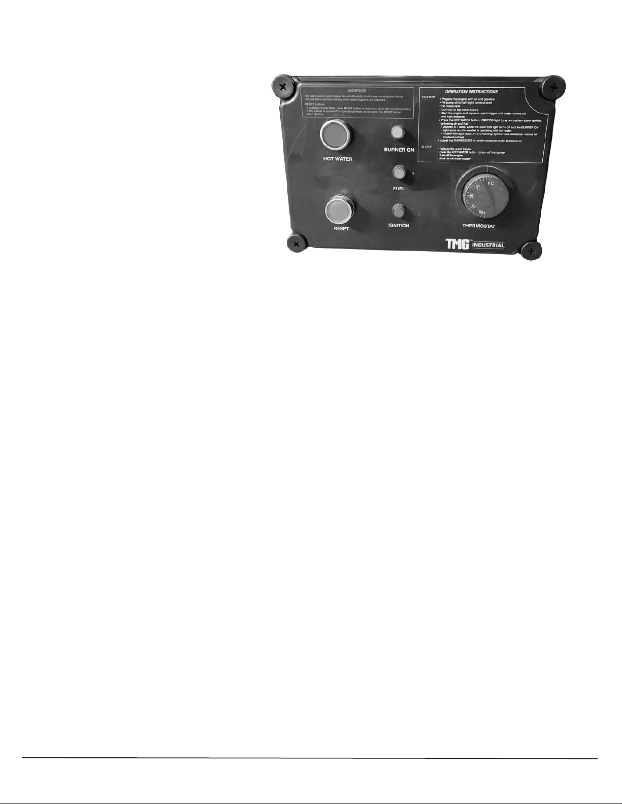
Electrical Control Center:
Important Note:
This high pressure washer is a hot
and cold machine. If you do not use
hot water, do not operate the electrical
control center
Switch:
1. HOT WATER: Hot water button switch
-When using hot water to clean, first need to press this switch. The switch comes with self-locking
function, press once to connect, press again to disconnect.
2. RESET: Reset button switch
-If the washer is turned off at normal operation, do not need to press the RESET button when you start to
use the machine next time.
-If the machine is failed to ignite, or ignites but fails to produce flame successfully, the IGNITION light
starts flashing. Go troubleshooting to fix the problem, press RESET button about 3 seconds until the light
is not flashing before you re-start the machine.
Important Note:
When the machine fails working, to avoid accidently wrong operating during troubleshooting, the
electrical control center is designed with memory function. Only the RESET button is activated after
troubleshooting, the machine can start to work properly.
3. THERMOSTAT: Temperature control switch
Indicator Light:
1.BURNER ON -- when the machine ignites and produces flame successfully, the combustion chamber is
working properly, the BURNER ON light turns on green
2.FUEL -- when diesel is low, the light turns on yellow
3.IGNITION --When you start the engine,
-If you do not need hot water, don’t turn on HOT WATER switch. Pull the trigger and stay on, you will get
the high-pressure water coming out.
-If you need hot water, turn on HOT WATER switch, pull the wand trigger and stay on until you feel high
pressure coming out. The IGNITION light turns on, indicating that the igniting is activated. The igniting will
stop automatically after the ignition is succeed and the flame is on.
-When the indicator light starts flashing, it indicates that igniting is not succeed, or the flame goes out.
You will need to stop the machine immediately and go troubleshooting (See diagnosis for details on Page
22)
WW W . TM G I ND U ST R IA L .C O M P1 0 /4 1 T oll Fr e e: 1 -8 7 7- 7 61 - 2 81 9

Spray Gun
Nozzle Quick
Coupler
Trigger
Black Nozzle for
Downstream Chemical
Application
Wand Nozzles
High Pressure Hose
Coil
Inner Steel
Layer
Hot Water Tank Interior
(Top Cover Removed):
Pressure Wand Assembly:
Ceramic
Casing
Coil Skin (outer
stainless steel
WW W . TM G I ND U ST R IA L .C O M P1 1 /4 1 T oll Fr e e: 1 -8 7 7- 7 61 - 2 81 9

OPERATING INSTRUCTIONS
1.Perform pre-start maintenance inspection on all applicable systems prior to operating the machine. This
is essential for the safe, effective and efficient operation. You will get optimum performance from your
system ONLY if these instructions and inspections are followed. Any indication that the pressure washing
system was not operated and maintained according to these instructions may cancel the manufacturers’
warranty.
Location – Be sure to install in an area that has sufficient air ventilation to support combustion of oil in
burner.
Controls – Make sure all controls turned to the off position.
Pump – Oil level - Level the pressure washer. Be sure oil level in the pump is correct on dip stick. If the
level is low, add the correct oil to the proper level. USE ONLY SAE 15 W-40 NON- DETERGENT OIL .
DO NOT OVER FILL.
Gas Engine - Gasoline level – The engine is a 4 cycle and uses regular octane, unleaded fuel. DO NOT
USE MIXED FUEL. Refer to the engine operation manual included with your pressure-washing unit.
Gas Engine - Oil level – The engine is a 4 cycle and uses 10W-30 detergent oil. Refer to Glossary or
engine manual.
Oil Fired Burner - Oil Tank Level – #2 Furnace oil is recommended for the burner oil tank, as it burns
cleaner and the burner requires less maintenance. Diesel fuel may be used as an alternative. Do not
overfill burner tank.
Visually inspect all electrical components to assure they are in good condition, showing No signs of
exposure, breakage or splicing.
Visually inspect all hoses, nozzles and guns to assure they are in good condition. If replacements are
necessary they must be rated to withstand the machines operating pressure and temperatures.
WW W . TM G I ND U ST R IA L .C O M P1 2 /4 1 T oll Fr e e: 1 -8 7 7- 7 61 - 2 81 9
10W-30
SAE30
5W-30

2.Attach high-pressure hose to hot water outlet quick connector. Attach the other end of high pressure
hose (with quick coupler) to spray gun. Ensure that quick disconnect connections are tightly locked
together. Apply a sharp pull on hose to confirm they are secured.
Attach wand nozzle specific to task requirements (i.e. chemical or pressure wash).
[Quick Coupling Operation – Pull back sleeve end and insert male end into nozzle quick coupler,
release sleeve and confirm connection by pulling on the nozzle].
3.Attach water source to water inlet located on pump. The water source must be attached with a good
quality standard garden type hose (1/2” minimum is required). Connect quick connector of the hose into
pump outlet fitting. Make sure that the inlet screen/filter is intact and fitted correctly. Turn on water source.
WATER MUST BE IN SUFFICIENT SUPPLY, AND PRESSURE MUST BE BETWEEN 20 –60 PSI TO
ENSURE PROPER AND SAFE OPERATION. Specific attention should be given if using a well water
supply. Ensure water is flowing from end nozzle with the trigger gun pulled. Deplete system of all air.
4.Start Gas Engine
Refer to instructions in engine manual. MAKE SURE THAT THE ENGINE EXHAUST IS NOT FACING ANY
FLAMMABLE MATERIALS.
WW W . TM G I ND U ST R IA L .C O M P1 3 /4 1 T oll Fr e e: 1 -8 7 7- 7 61 - 2 81 9

5.Burner operation
Be sure water is flowing through water heater coil before turning on HOT WATER switch. Turn thermostat
to desired temperature. Burner will ignite and remain in operation as long as there is sufficient water flow
to satisfy the pressure switch and temperature control.
IF YOU EXPERIENCE IGNITION FAILURE, DO NOT ATTEMPT TO RESTART BURNER! EXCESS FUEL
AND VAPORS MAY HAVE ACCUMULATED AND THE CHAMBER MAY BE HOT. THE UNIT MUST COOL
DOWN BEFORE RESTART CAN BE ATTEMPTED.
Warning: Condensation on Coil
When cold water is being pumped through the heater coil and the burner is firing, condensation
may form at times on the coil and drip down into the burner compartment. This can be
particularly noticeable on cold, humid days giving the false appearance of a leaking coil. A
leaking coil or system will be evident if the pump keeps cycling with the trigger released. The
pump head pressure should read ‘0’.
Electrically Operated Burners – These models generate 12V from the gasoline engine and
provide the necessary power for the burner. IF YOU REQUIRE UPGRADES OR MODIFICATIONS
TO YOUR EXISTING ELECTRICAL SYSTEM IN ORDER TO OPERATE YOUR PRESSURE
WASHER, THEY MUST BE PERFORMED BY A LICENSED ELECTRICIAN AND BE COMPLETED
IN ACCORDANCE TO ALL APPLICABLE CODES
IN YOUR AREA OF OPERATION. The power supply must be adequate for your specific unit.
Make sure to verify the data plate for your machine’s specific requirements (i.e. voltage,
amperage, etc.).
6.Pressure adjustment - The pressure regulator (unloader) is located on the pump (see pages 19, 21 & 23
diagrams. It controls the pressure being generated by the pressure washer. This regulator may be
adjusted to the desired pressure by turning the adjustment knob. Turning the adjustment knob clockwise
will increase the pressure. NEVER OPERATE SYSTEM AT A HIGHER PSI THAN THE MAXIMUM RATING.
This machine has been adjusted to operate at a specific maximum pressure as per the machine
specifications. Pressure may be reduced for lighter use by turning the Pressure Regulator/Unloader
counter clockwise. If continuing to turn the unloader clockwise does not increase the pressure, then this
implies the maximum has been reached for the system. Any further turning of the unloader will cause the
pressure to spike when the wand trigger is released, resulting in possible damage to the machine. To avoid this
effect, loosen the unloader (counter-clockwise) until the pressure just starts to drop (see pump head pressure
gauge) and until it no longer exceeds the maximum pressure rating for the machine.
WW W . TM G I ND U ST R IA L .C O M P1 4 /4 1 T oll Fr e e: 1 -8 7 7- 7 61 - 2 81 9

7.You are now ready to start the cleaning operation - Pull trigger on the pressure wand assembly to start
cleaning. To stop the pressurized water, release the trigger. DO NOT LEAVE UNIT RUNNING WHEN NOT
IN USE.
8.To stop Burner operation – Again press HOT WATER switch and run pump for two minutes with
trigger gun pulled to allow coil to cool down. Squeeze and release the trigger for the second time in order
to relieve the pump system of pressure.
9.Prior to storage – Inspect pressure washer for any damage or required maintenance. If your machine is
to be exposed to cold weather, please refer to winter pump/coil instructions found in this manual. If
possible, do not allow unit to remain outside in the elements.
10.Warning – If unit is left running while not in use, pump damage may occur. Do not leave unit running
while not in use!
CHEMICAL APPLICATION
Downstream Chemical Injection: Standard (Direct Drive Units) High Pressure Soap
(Optional Feature)
NOTE: Do not remove back flow preventer as chemical may flow back into potable water source.For
standard chemical injection, ensure the black nozzle is properly fitted at the end of the wand. The
chemical injector will not function if this nozzle is not fitted.
1.Chemical preparation – Select detergent/chemical that best suits your cleaning task. Prepare dilution
according to the manufacturer’s instructions. The volume of chemical being used may be adjusted at
valve located on the chemical injector.
2.Insert the intake hose, located on the chemical injector at the pump, into the chemical being used.
3.Fit black nozzle on the standard wand, or for the dual wand, turn adjustment knob on, and adjust for
required flow rate. For high pressure soap systems, the black nozzle is not needed; use one of the
other wand nozzles.
WW W . TM G I ND U ST R IA L .C O M P1 5 /4 1 T oll Fr e e: 1 -8 7 7- 7 61 - 2 81 9

4.To apply chemical, engage trigger on pressure wand assembly. Turn chemical injector’s nipple to
adjust flow. For the high pressure soap systems, open ball valve and engage trigger.
5.Chemical can now be applied through pressure wand assembly. It will take 5 – 15 seconds for
chemical to travel to spray nozzle. The volume of chemical being used may be adjusted at the
chemical injector.
6.For best results apply chemical from bottom to top, and allow for proper penetration time prior to
rinsing. Do not allow chemical to dry. Rinse from bottom to top and then top to bottom.
WINTER PUMP/ COIL PROTECTION
The following procedure MUST be used when the pressure washing unit is stored at
temperatures below freezing.
1.All water must be drained or blown (via compressed air) from system. Connect a short piece of male
fitted ½” garden type hose on to the female inlet on the pump.
2.Place the open end of the hose into a wide mouthed container of full strength, winter rated, vehicle
windshield washing fluid or Anti-Freeze, RATED FOR MINIMUM -40°C.
3.Connect the pressure wand assembly.
4.Start the engine and engage the trigger on the pressure gun. Operate the system until the fluid runs
the same color as the windshield washing fluid. Your machine is now prepared for storage.
5.Disconnect fluid supply, blow out with compressed air, and cap end.
GENERAL MAINTENANCE
Burner Maintenance
NOTE: Repair of the burner is to be done by authorized and trained burner professionals only.
The oil filter cartridge should be replaced every year to prevent fuel contamination and plugging of fuel
pump and nozzle of oil burner. The nozzle should also be replaced at least once every year or twice if
used daily and if poor combustion begins to occur.
WW W . TM G I ND U ST R IA L .C O M P1 6 /4 1 T oll Fr e e: 1 -8 7 7- 7 61 - 2 81 9

Final adjustments to burner include fuel pressure adjustment for controlling water temperature (tighten
fuel pressure adjustment screw slightly to increase desired output temperature) and air band adjustment
for combustion efficiency. A combustion test kit should be used for these final adjustments. Check
SPECIFICATIONS chart for the burner oil pressure corresponding to your model and be sure not to
exceed this pressure.
If the burner floods with oil: run machine with heat on until all excess oil is burned off (this can take up to
a couple of hours). If excess oil is not properly dealt with, the ceramic casing can absorb excess oil,
causing a fire hazard. DO NOT LEAVE MACHINE UNATTENDED WHILE MACHINE IS FLOODED.
General Maintenance and Care
If the water heater is likely to be exposed to freezing weather then it should be winterized according to
the winter pump/coil protection procedure in the previous section. Alternate methods may not completely
protect the components. Damage from freezing is not a warrantable item.
Water Condition
Use a softener on your water system if local water is known to be high in mineral content. The
advantages of soft water are very beneficial: prevents scale buildup in heater coil, cleans better with
considerably less detergent, prevents streaking on painted surfaces and glass when rinsing.
Descaling Heater Coil Procedure
NOTE: Descaling of the heater coil is to be done by authorized and trained professionals only.
The best way to acidize the coil is with a circulation pump capable of handling acids.
1.Fill a plastic container with a suitable acid diluted with water to desired strength.
2.Connect discharge from the circulating pump to the hot water outlet on the water heater with a suitable
hose. Connect the inlet of the circulating pump to the acid container with suction hose from the pump
module and use it as a return hose to the acid container. As acid dissolves the scale it becomes
neutralized, so about every five minutes add more acid to the container until all the scale has been
removed from the coil. Flush out coil thoroughly with water after descaling.
WW W . TM G I ND U ST R IA L .C O M P1 7 /4 1 T oll Fr e e: 1 -8 7 7- 7 61 - 2 81 9

MAINTENANCE CHECKLIST
Maintenance for Pump
Daily
1.Check oil for proper level and adjust accordingly.
2.Examine the quality of the oil.
3.Check pump for oil and/or water leaks.
4.Inspect and clean inlet filters.
Weekly
1.Examine all fittings, components, hoses, connections, and nozzles for
damages, loose parts, or leaks. – Replace accordingly—
Recommendation for Oil Changes and Component Replacement
1.Change the oil in the pump after the first 50 hours and every 500 hours after the initial oil
change. Use 15W-40 Non-Detergent for GP Pumps.
2.Change all other components on the pump as needed.
Maintenance for Gasoline Engine
Daily
1.Check oil for proper level and adjust accordingly.
2.Examine the quality of the oil
3.Examine the air cleaner element
Weekly
1. Examine engine components for damages, loose parts, or leaks.
WW W . TM G I ND U ST R IA L .C O M P1 8 /4 1 T oll Fr e e: 1 -8 7 7- 7 61 - 2 81 9

Recommended Schedule for Oil Changes and Component Replacements
1.Change engine oil after first 5 hours and every 100 hours after the initial oil change. Use
10W-30 engine oil.
2.Replace Spark Plug every 100 hours.
3.Change air cleaner element every 100 hours.
4.Check fuel filters every 300 hours.
5.Change all other components on engine as needed.
Maintenance for Ignition System
1.Electrode Setting:(See illustration below.)
Periodically check wiring connections. If necessary
to adjust electrodes, use diagram.
2. Flame Detector:
Flame detector is a very key part in ignition system,
it determines whether ignition is successful or not.
When the machine starts, stops or fails to ignite,
constantly black smoke or bituminous coal may
stay on the glass cover of the flame detector. When
the glass cover is filled with soot, the flame detector
will be disabled and not being able to work properly,
and the machine will alarm. It needs to be cleaned
and maintained to wipe off all black bituminous coal
on the surface with a soft cloth at regular bases.
1. Lift the machine and remove the ignition
2. Clean the surface of flame detector for bituminous coal
WW W . TM G I ND U ST R IA L .C O M P1 9 /4 1 T oll Fr e e: 1 -8 7 7- 7 61 - 2 81 9
Ignition Disc
Electrode
Flame
Dectector
Fuel Nozzle

QUICK DIAGNOSTICS AND SOLUTIONS GUIDE
PUMP
TYPE OF OIL
GP Pump
SAE 15W-40 Non-Detergent
PROBLEM
POSSIBLE CAUSES
SOLUTIONS
PRESSURE
No pressure or
Very low
pressure
Metal in oil
- Examine oil in pump to see if there is metal in oil.
- If you find traces or pieces of metal, your
pump has damaged components.
Dirt in water
-
Verify if there is dirt in nozzle tip or in valves in
pump.
-
If nozzle is plugged, clean or replace it.
-
If valves in pump are clogged, clean valves.
-
If valves in pump are damaged or pitted,
replace valves.
Wrong nozzle size
- Make sure you have the right nozzle size. The
black nozzle will drop pressure in order to use
chemical injector and is only for soap or chemical. If
you are not using soap, use a different color.
Pressure too high
Wrong nozzle size
- Make sure you have the right nozzle size.
Unloader adjusted improperly
or damaged
-
Check pressure of pump with a pressure gauge
and adjust to desired pressure.
-
If you cannot reduce pressure, replace unloader.
WW W . TM G I ND U ST R IA L .C O M P2 0 /4 1 T oll Fr e e: 1 -8 7 7- 7 61 - 2 81 9
Table of contents
Other TMG Pressure Washer manuals