TOA-DKK ODL-1610A User manual
Please keep this instruction manual close at hand of the persons who are in charge of
the operation of this product.
Before operating this product, please read this instruction manual carefully for its
correct handling.
OIL FILM DETECTOR
(High sensitive model)
MODEL ODL-1610A
No. ODL-IB55900E

Model: ODL-1610A Introduction
-
1
-
Introduction
(a)Thank you for your purchase of our product. The Model ODL-1610A Oil Film Detector (High
sensitive model) (hereafter called “instrument” or “product”) is a sensing/alarm device that
continuously monitors the presence of oil films on a water or floor surface. This product is based
on the principle that the reflectance of an oil film is greater than that of water.
Receiving device
Oil Film Detector
(Model ODL-1600)
Monitoring Example
(b)This product consists of a detector and a transmitter. The detector consists of a light source, light
source scanning unit, reflecting mirror, light receiving section and a signal processor. The detector
monitors the presence of oil films from above with no contact and sends oil film detected signals,
self-diagnostic information and received light intensity level, etc. to the transmitter via digital
communication. The transmitter displays/outputs an oil alarm signal, self-diagnostic information
and light received signal intensity, etc., according to communication signals from the detector. It
also performs setting of alarm and self-diagnostic conditions, etc.
(c)Since this product outputs an oil film-detected alarm signal and an error alarm signal, it is possible
to build an alarm system in combination with an alarm buzzer, etc.
(d)The product may indicate or output an incorrect measured value due to the following reasons. We
recommend preparing a system such that the related facilities will not be damaged even in cases
like these.
•Any problem of the product, such as deterioration or damage of the sensing section or inadequate
cable insulation.
•Inadequate operating condition setting or calibration operation.
•Electrical interference such as noise in the vicinity or inadequate grounding.
•Other unpredictable phenomena
(e)Since important items are described in “Safety Information,” read the contents carefully.
(f) The product should be handled by persons who have received proper training. In addition, for
technical services such as repairs, ask a specialist to do who is qualified for the technical
certification system in our company or a person who has technical skills equivalent to that
certification system.
Model: ODL-1610A Safety Information
-
2
-
Safety Information
(1) Meaning of markings
The signal terminology and symbols related to warnings in the instruction manual are defined
below. The alert symbol mark ( : General caution mark) indicates the possibility of hazard or
damage and also means “Refer to the instruction manual.”
:
Indicates the degree of hazard which can lead to death or serious injury if you fail to operate the
product properly.
Serious injury means an injury such as loss of sight, burns (high temperature or low temperature),
electric shock, bone fracture and poisoning, and the aftereffects of the injury remains or the injury
requires hospitalization or long periods of outpatient treatment.
:
Indicates the degree of hazard/loss which can result in injury or property damage if you fail to operate
the product properly.
Injury means an injury not requiring hospitalization or long periods of outpatient treatment and refers
to burns or electric shock. Property damage refers to widespread damage to the home, household
goods and livestock, pets, equipment, materials, etc. (damage to other than the product itself).
【IMPORTANT】Indicates important matters other than and . They are the
m
atters such as preventing damage to the product main body, preventing data
destruction, preventing wasting time, maintaining performance, and observing
regulations.
〔NOTE〕 Indicates comments, reasons, background information, a case example and other
items to help the reader understand the meaning.
>> Indicates reference items.
①, ②, ③Indicates item numbers such as the ones used in operations.
(2) Safety compliance items
Hazardous Gasses
Do no use the product in an area where explosive gas, flammable gas exists. Using
the product in any of these areas can cause explosion or fire.
Electric Shock
Do not touch the terminals inside the controller while power is applied. Touching the
terminals may cause electric shock.
The ground terminal must be grounded. If the terminal is not grounded and a problem
occurs in the power supply system, electric shock may result.

Model: ODL-1610A Safety Information
-
3
-
Laser beam
This product uses Class 2 (1mW or less, 400 to 700nm wavelength) laser defined in
JIS C6802-2005 “Laser Product Safety Standard”. Do not look directly into the laser
beam with your eyes and do not make an observation using an optical means (such
as lens). If you look directly into laser beam for a long time, you could damage your
sight.
Disassembly and Modification
Do not disassemble or modify the sections of the product that are not described in
the instruction manual. The product can be damaged.
Warning Label Lost
If any warning label affixed to this product becomes too difficult to read or lost,
please order a new one through your local sales agent or our sales office and affix it
to its original position.
Disposal
In case you dispose of this product or any part of this product, handle it as industrial
waste as specified by law.
(3) Notes on use of the instruction manual
Important items such as “Safety compliance items” are described in this manual. Handle the manual
as follows:
(a)The instruction manual is required not only at the start of operation but also required when
maintenance is performed or in case a failure occurs. Please keep the manual at hand all the time so
that the operator who actually operates the product can read the manual at any time.
(b)If the manual is lost or too smeared to read, please order a new copy through your local sales agent
or directly from our sales office.
(c)Some of the diagrams used in the manual or on product labels may be modified with part of their
shapes or displays omitted or they may be described in abstract form. In addition, numbers etc.
shown on the screen example are just examples for such cases.
(d)The contents of the manual may be changed without prior notice for reasons such as to improve
performance.
(e)Intellectual property right of the manual belongs to DKK-TOA. All or part of the manual must not
be reproduced without permission.

Model: ODL-1610A Warranty
-
4
-
Warranty
(1) Warranty Coverage
DKK-TOA Corporation (DKK-TOA) warrants its products against defective material or workmanship for the warranty
period.
(a) The warranty period is one year from the date of delivery to the original user. If the date of delivery cannot be
specified, the warranty period is 24 months from the month following the date of manufacture shown on the product
nameplate.
(b) Specific written agreements with DKK-TOA, if any, shall take precedence over this warranty.
(c) The limitation of warranty described herein may not apply where applicable laws do not allow such limitation.
(2) Limited Warranty
This warranty does not cover the cases listed below.
(a) Direct or indirect failure or damage caused by the use of the product for a purpose or in a manner not prescribed by
the specifications or the instruction manual for the product.
(b) Direct or indirect failure or damage caused by force majeure, including but not limited to an act of God, natural
disaster such as earthquake, storm and flood damage, and lightning, fire, accident, abnormal voltage, salt damage,
gas damage, labor unrest, acts of war (declared or undeclared), terrorism, .civil strife, or acts of any governmental
jurisdiction.
(c) Failure or damage caused by any repair or modification not authorized by DKK-TOA.
(d) Failure or damage caused by the transport, moving, or dropping of the product after the purchase that is not
attributable to DKK-TOA.
(e) Electrodes and consumables (The warranty period for each part has priority when the period is shorter than that for
the main unit of the product. If the customer requires any part after more than six months from the date of manufacture,
consult DKK-TOA or its distributor.)
(f) Failure or damage caused by the use of consumables, parts, or software not supplied by DKK-TOA.
(g) Malfunctions or damage caused by the use of connecting equipment not supplied by DKK-TOA
(h) Loss of data, settings, programs, or software stored on the product not attributable to DKK-TOA.
(i) Any product other than DKK-TOA’s, if specified by the purchaser or user, that incorporates, or is incorporated into or
combined with DKK-TOA’s products (*1). In such cases, this warranty covers DKK-TOA’s products only.
(j) Any product not under proper maintenance in accordance with the instruction manual furnished by DKK-TOA.
(k) Products without a nameplate (excluding products proved to have been delivered by DKK-TOA).
EXCEPT AS EXPRESSLY SET FORTH IN THE PRECEDING SENTENCES, DKK-TOA MAKES NO WARRANTY OF
ANY KIND WHATSOEVER WITH RESPECT TO ANY PRODUCT. DKK-TOA EXPRESSLY DISCLAIMS ANY
WARANTY IMPLIED BY LAW, INCLUDING BUT NOT LIMITED TO ANY WARRANTY OF MERCHANTABILITY OR
FITNESS FOR A PARTICULAR PURPOSE.
LIMITATION OF REMEDIES: In the event that a defect is discovered within the warranty period, DKK-TOA or its
authorized distributor will, at its option, repair or replace the defective product or its part, or will refund the purchase price
of the product. THIS IS THE EXCLUSIVE REMEDY FOR ANY BREACH OF WARRANTY.
LIMITATION OF DAMAGES: IN NO EVENT SHALL DKK-TOA BE LIABLE FOR ANY INCIDENTAL OR
CONSEQUENTIAL DAMAGES OF ANY KIND FOR BREACH OF ANY WARRANTY, NEGLIGENCE, ON THE BASIS OF
STRICT LIABILITY, OR OTHERWISE.
(3) Others
(a) Maintenance parts (*2) for product will normally be supplied for five years (*3) from the date manufacturing and sales
are discontinued.
(b) The cause of any malfunction or damage shall be determined by a DKK-TOA technician.
(c) For repairs, contact a local distributor in your country or state.
*1: Warranties for products from other companies must be maintained by the user.
*2: Maintenance parts refers to parts that are required to maintain operation of the product.
*3: This five-year period is subject to availability of parts or their replacement.
Model: ODL-1610A Reading Guide
-
5
-
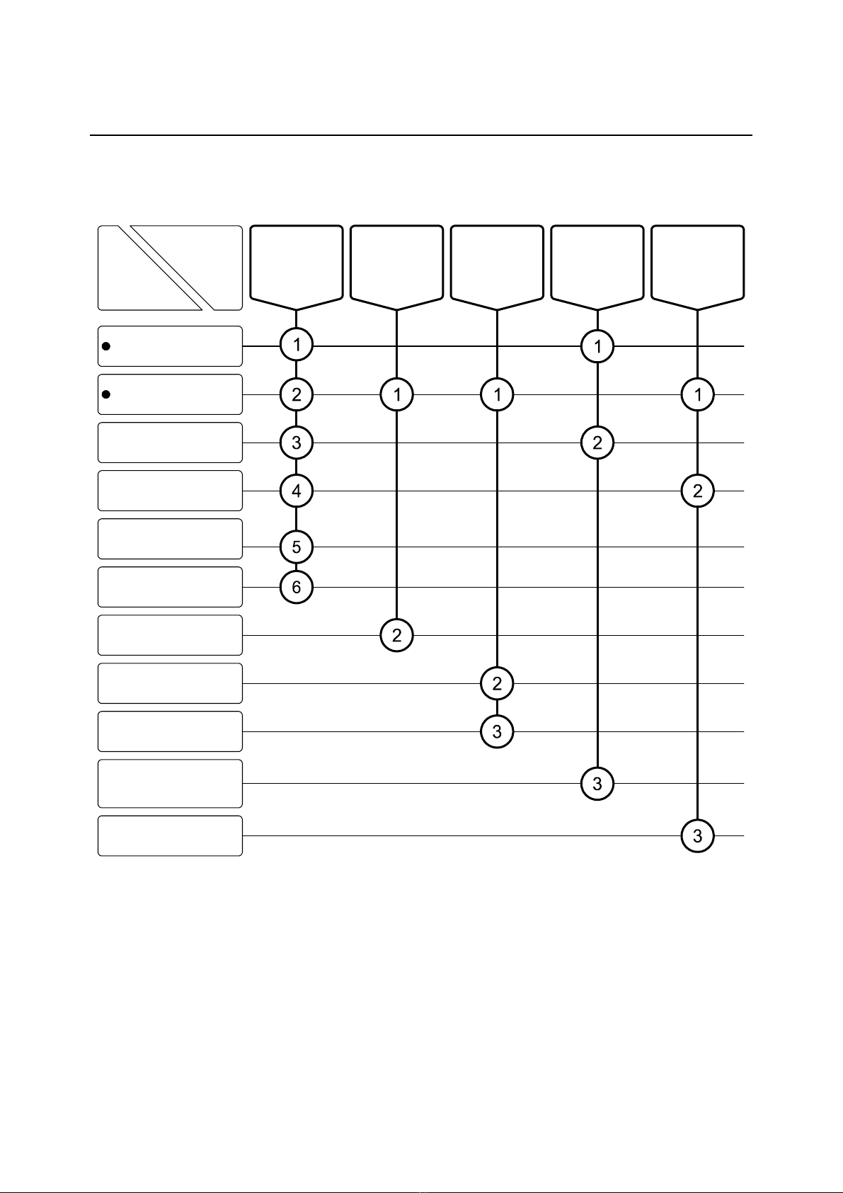
Reading Guide
Refer to the necessary sections of this instruction manual depending on your purposes such as
understanding the outline of this product or starting the product as shown below. The numbers in
circles indicate sections to be referred to in sequential order.
Purpose
Section
Perform
respective
operations
Maintenance,
inspection, and
troubleshooting
Understand
the outline of
this product
Check
installation,
piping and
wiring
Start
(start-up)
1. Configuration
Safety Information
Introduction
2. Operation
8. Specifications and
Explanation of
Operation
9. Installation
3. Alarm Operation
Check
4. Calibration
5. Modes of Operations
6. Maintenance
7. Troubleshooting

Model: ODL-1610A Table of Contents
-
6
-
Table of Contents
●Introduction······················································································· 1
●Safety Information ········································································· 2
(1) Meaning of markings ⋅⋅⋅⋅ 2
(2) Safety compliance items ⋅⋅⋅⋅ 2
(3) Notes on use of the instruction manual ⋅⋅⋅⋅ 3
●Warranty ···························································································· 4
●Reading Guide ················································································ 5
1. Configuration ················································································ 9
(1) Names of main components ⋅⋅⋅⋅ 9
(2) Operation Keys and Screen Display ⋅⋅⋅⋅ 12
(3) Detector monitor LED ⋅⋅⋅⋅ 13
(4) Communication display LED ⋅⋅⋅⋅ 14
2. Operation ······················································································15
2.1 Operation Start ················································································15
2.2 Operation Stop and Restart·································································16
(1) Operation stop ⋅⋅⋅⋅ 16
(2) Operation restart ⋅⋅⋅⋅ 16
3. Alarm Operation Check···························································17
4. Calibration·····················································································19
5. Modes of Operations································································22
5.1 Modes and Operation Map··································································22
(1) Mode switching ⋅⋅⋅⋅ 22
(2) LCD high contrast⋅⋅⋅⋅ 22
(3) Key lock ⋅⋅⋅⋅ 23
(4) Operation map ⋅⋅⋅⋅ 24
5.2 Operations in Measurement Mode and Maintenance Mode (MEAS and ST-BY) ·26
5.3 Operations in the Setting Mode····························································29
(1) Oil alarm level (ALM LEVEL) ⋅⋅⋅⋅ 29
(2) Oil alarm (ALM CT, ALM CT TIME, ALM CONT TIME) ⋅⋅⋅⋅ 31
(3) Hold time (ALM HOLD TIME) ⋅⋅⋅⋅ 33
(4) Water surface detection level (WATER ERR LEVEL) ⋅⋅⋅⋅ 33
(5) Laser scanning range (SCAN SIZE) ⋅⋅⋅⋅ 34
(6) Analog output (OUTPUT MODE) ⋅⋅⋅⋅ 35

Model: ODL-1610A Table of Contents
-
7
-
(7) Response speed (OUTPUT RESPONSE) ⋅⋅⋅⋅ 37
(8) Burnout (OUTPUT B.OUT) ⋅⋅⋅⋅ 38
(9) Heater switch (HEATER) ⋅⋅⋅⋅ 39
(10) Date and Time (DATE, TIME) ⋅⋅⋅⋅ 40
(11) Automatic release of maintenance mode (M_RETURN) ⋅⋅⋅⋅ 41
(12) Detection method (DETECT MODE) ⋅⋅⋅⋅ 42
(13) Output signal (DO-□□□□) ⋅⋅⋅⋅ 42
(14) LCD Back light (BACK LIGHT CTL,BACK LIGHT TIME) ⋅⋅⋅⋅ 43
(15) LCD high contrast (LCD MAX CTL, LCD MAX TIME) ⋅⋅⋅⋅ 44
5.4 Operations in the Option Setting Mode ··················································46
(1) Detector address (DETECTOR ADDR) ⋅⋅⋅⋅ 46
(2) Analog output item (4-20mA OUT) ⋅⋅⋅⋅ 47
(3) Analog output adjustment (CAL 4-20mAOUT) ⋅⋅⋅⋅ 47
(4) Calendar (DATE & TIME) ⋅⋅⋅⋅ 48
(5) External digital interface (COMMUNICATION) ⋅⋅⋅⋅ 49
(6) Contrast adjustment (LCD CONTRAST) ⋅⋅⋅⋅ 51
(7) System information (ABOUT) ⋅⋅⋅⋅ 51
(8) Detector parameter initialization ⋅⋅⋅⋅ 52
6. Maintenance ················································································54
6.1 Maintenance List ··············································································54
6.2 Accessories and Spare Parts·······························································55
6.3 Window Cleaning··············································································56
6.4 Replacement of Silica Gel ··································································56
6.5 Replacement of Light Source Unit ························································56
6.6 Application of Lubricant······································································56
6.7 Replacement of Varistor Unit·······························································57
7. Troubleshooting ··········································································59
7.1 Errors and Handling ··········································································59
7.2 Troubleshooting of Transmitter ····························································64
(1) Detection error ⋅⋅⋅⋅ 64
(2) Reflected light output (analog) error ⋅⋅⋅⋅ 64
(3) Alarm contact output error ⋅⋅⋅⋅ 65
7.3 Troubleshooting of Detector ································································66
7.4 Fuse Replacement············································································67
(1) Replacing the fuse in the transmitter ⋅⋅⋅⋅ 67
(2) Replacing the fuse in the detector ⋅⋅⋅⋅ 67
8. Specifications and Explanation of Operation ·················69
8.1 Specifications ··················································································69
8.2 Explanation of Operation ····································································71
(1) Principle of detection ⋅⋅⋅⋅ 71
(2) Explanation of operation ⋅⋅⋅⋅ 73

Model: ODL-1610A Table of Contents
-
8
-
(3) Example of detection ⋅⋅⋅⋅ 74
9. Installation ····················································································76
9.1 Installation ······················································································76
(1) Installation location (Detector) ⋅⋅⋅⋅ 76
(2) Installation location (Transmitter) ⋅⋅⋅⋅ 77
(3) Installation example ⋅⋅⋅⋅ 77
9.2 Wire Connection···············································································79
(1) Applicable cables ⋅⋅⋅⋅ 79
(2) Cable port ⋅⋅⋅⋅ 80
(3) Terminals of transmitter ⋅⋅⋅⋅ 81
(4) Terminals of detector ⋅⋅⋅⋅ 83
9.3 Addition of Detector ··········································································84
(1) Connecting the cables ⋅⋅⋅⋅ 84
(2) Changing the address (Detector) ⋅⋅⋅⋅ 85
(3) Changing the terminal resistance switch ⋅⋅⋅⋅ 86
(4) Changing the address (Transmitter) ⋅⋅⋅⋅ 86
(5) Screen display (When two detectors are connected) ⋅⋅⋅⋅ 86
(Last page ⋅⋅⋅⋅ 87)

Model: ODL-1610A 1. Configuration
-
9
-
1. Configuration
(1) Names of main components
Transmitter Eyebolt
Detector cover
Bracket
Detector body
Mounting pipe
Example of Instrument Construction
Model: ODL-1610A 1. Configuration
-
10
-
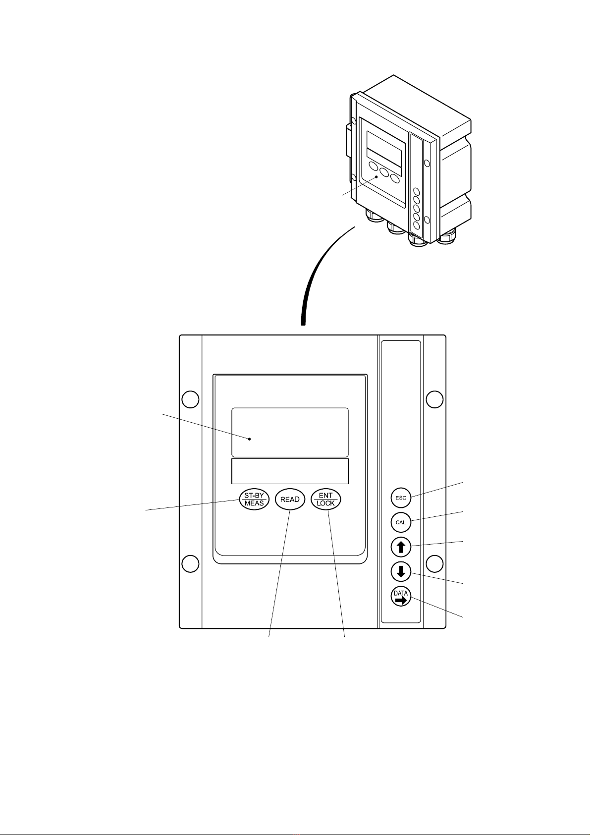
Operation panel
Display panel
Measure/
Standby key
Escape key
Cal key
Up key
Down key
Data key
Read key Enter/lock key
Transmitter

Model: ODL-1610A 1. Configuration
-
11
-
Power switch
Fuse holder
Terminal board
Electric Section 1 of Detector
Detector address
dip switch
Detector monitor
LED
Communication
display LED
Terminal resistance
switch
Electric Section 2 of Detector
Model: ODL-1610A 1. Configuration
-
12
-
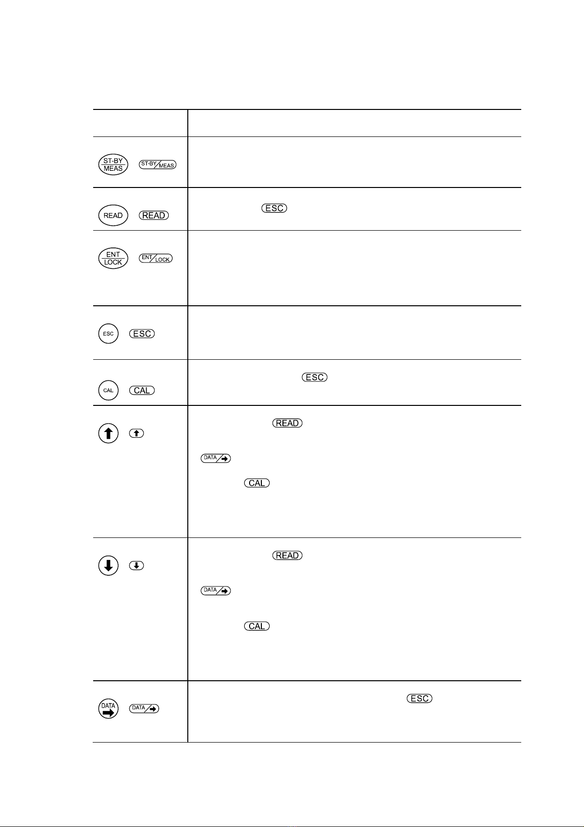
(2) Operation Keys and Screen Display
Functions of Operation Keys
Operation key
(symbol in the text) Function
Measure/Standby key
( )
•Pressing this key for 4 seconds or more switches the instrument to the maintenance
mode.
•Pressing this key for 4 seconds or more returns the instrument to the measurement
mode.
Read key
( )
•Displays a parameter in the bottom of the screen. (bottom display)
•When you press after a parameter is displayed, the parameter disappears.
Enter/Lock key
( )
•The number or symbol you entered is confirmed and at the same time the display
switches to the next screen.
•Pressing this key for 4 seconds or more in the measurement mode locks the other
operation keys.
•Pressing this key for 4 seconds or more when the other operation keys are locked,
they are unlocked.
Escape key
( )
•Restores the state before operation.
•This key cancels the input.
•By pressing this key for 4 seconds or more during calibration, you can cancel the
calibration in the middle.
CAL key
( )
•Pressing this key in the maintenance mode switches the instrument to the
calibration mode. Pressing returns the instrument to the maintenance mode.
Up key
( )
•Every time you press this key after displaying a parameter in the bottom of the
screen by pressing in the measurement mode, each parameter is displayed
one after another.
•Every time you press this key after switching to the setting mode by pressing
in the maintenance mode, each parameter is displayed one after another.
•Every time you press this key after switching the instrument to the calibration mode
by pressing in the maintenance mode, each calibration operation is displayed
one after another.
•When you press this key when you are setting a numeric value in the setting mode
or calibration mode, the number you intend to set increases or the choice is
switched.
Down key
( )
•Every time you press this key after displaying a parameter in the bottom of the
screen by pressing in the measurement mode, each parameter is displayed
one after another (in the reverse manner to the Up key).
•Every time you press this key after switching to the setting mode by pressing
in the maintenance mode, each parameter is displayed one after another (in
the reverse manner to the Up key).
•Every time you press this key after switching the instrument to the calibration mode
by pressing in the maintenance mode, each calibration operation is displayed
one after another (in the reverse manner to the Up key).
•When you press this key while setting a numeric value in the setting mode or
calibration mode, the numeric value you intend to set decreases or the choice is
switched.
Data key
( )
•Pressing this key in the maintenance mode switches the instrument to the setting
mode and displays “PARAM” on the screen. Pressing causes the instrument
to return to the maintenance mode.
•When you press this key while setting a numeric value in the setting mode, the
highlighted decimal place changes, one place to the right.

Model: ODL-1610A 1. Configuration
-
13
-
〔NOTE〕•For mode and screen group >> 5.1(1) “Mode switching”
•For screen configuration and switching >> 5.1(3) “Operation map”
Screen Display
Display Type
Display Function
Detection display •In the measurement mode and maintenance mode, “RUN” is
displayed in normal conditions. When an alarm occurs, “ALM” is
displayed.
Bottom display •In the measurement mode and setting mode, a parameter is displayed
in the bottom of the screen.
Mode display MEAS •Indicates that the instrument is in the measurement mode.
ST-BY •Indicates that the instrument is in the maintenance mode.
PARAM •Indicates that the instrument is in the setting mode.
CAL •Indicates that the instrument is in the calibration mode.
Model name display •Indicates the model name of the connected detector.
Heater indication •Indicates that the heater option is on.
Error display •Indicates that an error is occurring in the instrument.
>> 7. “Troubleshooting”
Time display •Indicates the current time.
Key lock indication •When displayed, it indicates that the keys are locked.
Oil film detection record •Displays the date (YY/MM/DD) and time (hh: mm) when an oil film
was detected in the past. >> 5. “Modes of Operations”
(3) Detector monitor LED
You can grasp light receiving status by the detector alone, based on the blinking interval and coloring
of the detector monitor LED.
(a)Green lamp lights (once) at short lighting time: When reflected light is detected.
(b)Green lamp lights (twice) at short lighting time: When normal oil film detection is difficult
because the reflected light level is too small.
(c)Green lamp lights (3 times) at short lighting time: Water surface detection is almost normal.
(d)Red lamp lights (3 times) at short lighting time: When an oil film has been detected
(e)Red lamp lights (once) at long lighting time: When the detector is in the hold state after detecting
an oil film.

Model: ODL-1610A 1. Configuration
-
14
-
1 frame
When determined as
“No reflected light detected”
LED lights: Green
When the transmission output
is less than 7mA and the
condition is not “No reflected
light detected”
Green
When the transmission output
is 7mA or more and no oil
alarm is output.
When the oil alarm threshold
is exceeded
Red (*)
When the oil alarm is on
* Red lamp lights preferentially.
Alarm contact is operating ON
(regardless of the frame)
Green
Red (*)
Lighting Time of Detector Monitor LED
(4) Communication display LED
The following two display functions are provided.
(a)Display of a channel number of the detector.
(b)Display of an error number when an error occurs in the detector.
Model: ODL-1610A 2.1 Operation Start
-
15
-
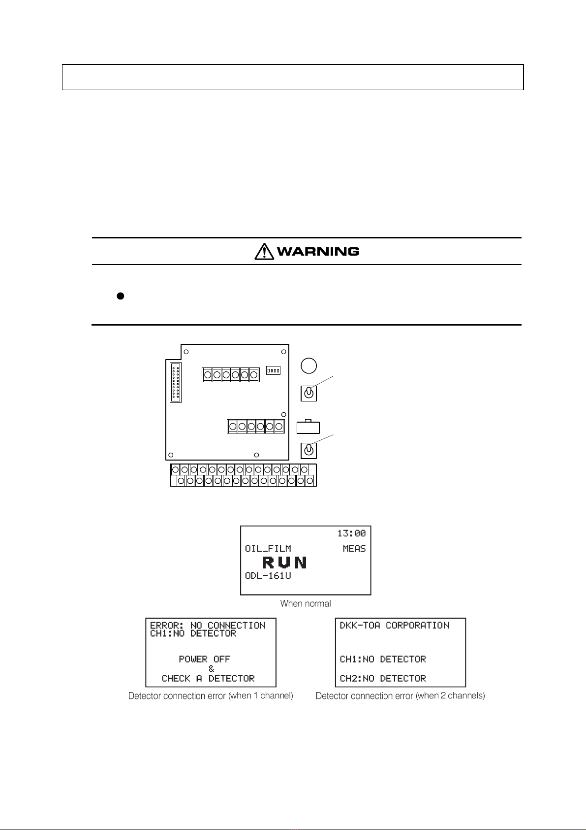
2. Operation
2.1 Operation Start
①Check. ⋅⋅⋅⋅⋅⋅ Make sure the installation is completed. >>8.1 “Specifications and Explanation of
Operation”, 9. “Installation”
②Turn on the power switch. ⋅⋅⋅⋅⋅⋅ Turn on the power switch of the transmitter in the following order:
•Lower switch →Upper switch
•After the screen display is switched one after another, the instrument enters the measurement
mode.
Electric Shock
Do not touch the terminals inside the controller while power is applied. Touching the
terminals may cause electric shock.
Power switch
(upper switch: for transmitter)
Power switch
(lower switch: for detector)
Power Switch Positions
Examples of Measurement Mode Screens

Model: ODL-1610A 2.2 Operation Stop and Restart
-
16
-
〔NOTE〕•If the power supply of the detector is off, if the cable is not connected or if the address
setting differs between the detector and transmitter, an error occurs. Check the address
setting and cable connection.
【IMPORTANT】•When you restart operation after the instrument was stopped for a long
time, perform alarm operation check. >> 3. “Alarm Operation Check”
③Perform warm-up operation. ⋅⋅⋅⋅⋅⋅ Standard warm-up time: Approx. 10 minutes.
④Perform calibration. ⋅⋅⋅⋅⋅⋅ >> 4. “Calibration”
⑤Check the operation conditions. ⋅⋅⋅⋅⋅⋅ >> 5.2 “Operations in Measurement Mode and
Maintenance Mode”
The instrument is now ready for normal operation.
2.2 Operation Stop and Restart
(1) Operation stop
Turn off the power switch. ⋅⋅⋅⋅⋅⋅ Turn off the power switches of the transmitter in the following order:
•Upper switch →Lower switch
〔NOTE〕•The settings of operation conditions, etc. are held even after the power supply is turned
off. No restriction applies to power-off timing.
•When properly done, lastly turn off the power switch on the distribution board.
(2) Operation restart
①Inspect the detector. ⋅⋅⋅⋅⋅⋅ Check the condition of the connected detector.
②Turn on the power switch. ⋅⋅⋅⋅⋅⋅ >> ②in 2.1 “Operation Start”
③Set the date and time. ⋅⋅⋅⋅⋅⋅ >> 5.3(10) “Date and time”
〔NOTE〕•When a long time period has passed since the power supply was turned off, the date and
time setting is reset. When restarting operation, check the date and time.
④Perform warm-up operation. ⋅⋅⋅⋅⋅⋅ Standard warm-up time: Approx. 10 minutes.
⑤Perform calibration, etc. ⋅⋅⋅⋅⋅⋅ >> 3. “Alarm Operation Check”, 4. “Calibration”
Model: ODL-1610A 3. Alarm Operation Check
-
17
-
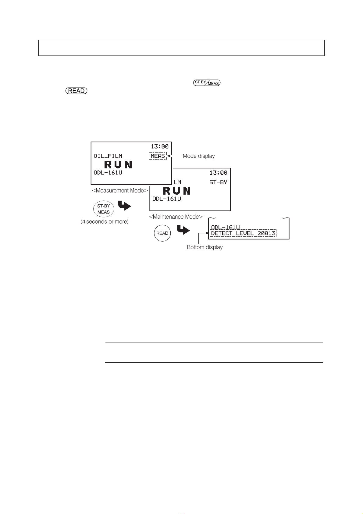
3. Alarm Operation Check
Perform alarm operation check by the following procedure:
①Make the detection level to appear. ⋅⋅⋅⋅⋅⋅ Press for 4 seconds or more then press
(when “MEAS” is displayed).
•After operation, the mode display and bottom display change as follows:
•Mode display: “MEAS” →“ST-BY”
•Bottom display: (Hidden) →“DETECT LEVEL”
②Check the detection level. ⋅⋅⋅⋅⋅⋅ Make sure that the numeric value on the bottom display is within
the following range.
•When the detector is installed on a water surface ⋅⋅⋅⋅⋅⋅ 17000 to 23000
〔NOTE〕•If a value of 10000 or less is often displayed, check whether the wave condition on the
water and the detector installation angle are normal.
③Place the calibration vessel. ⋅⋅⋅⋅⋅⋅ Fill the calibration vessel with oil such as light oil or kerosene
and place it on the laser beam scanning surface of the detector.
【IMPORTANT】•For calibration vessel, use the standard accessory vessel (Code No.
136C035).
〔NOTE〕•If the calibration vessel cannot be placed directly on the laser beam scanning surface,
place the calibration vessel above the laser beam scanning surface, with no contact.
④Check that an oil alarm is generated.
〔NOTE〕•Depending on the set conditions, it may take some time until an alarm is generated.
>> 5.3(2) “Oil alarm”

Model: ODL-1610A 3. Alarm Operation Check
-
18
-
⑤Check that error “E-4” is generated. ⋅⋅⋅⋅⋅⋅ Use the following procedure:
Prepare a black fiber or a lusterless rubber sheet that absorbs or diffuses light.
Place on the laser beam scanning surface.
As in ④, wait until an error is generated.
〔NOTE〕•If it is set to detect a liquid or oil leakage on a floor surface, instead of on a water surface,
“E-4” is not generated. >> 5.3(12) “Detection method”
•When an error is detected in ③to ⑤>> 7. “Troubleshooting”
Model: ODL-1610A 4. Calibration
-
19
-
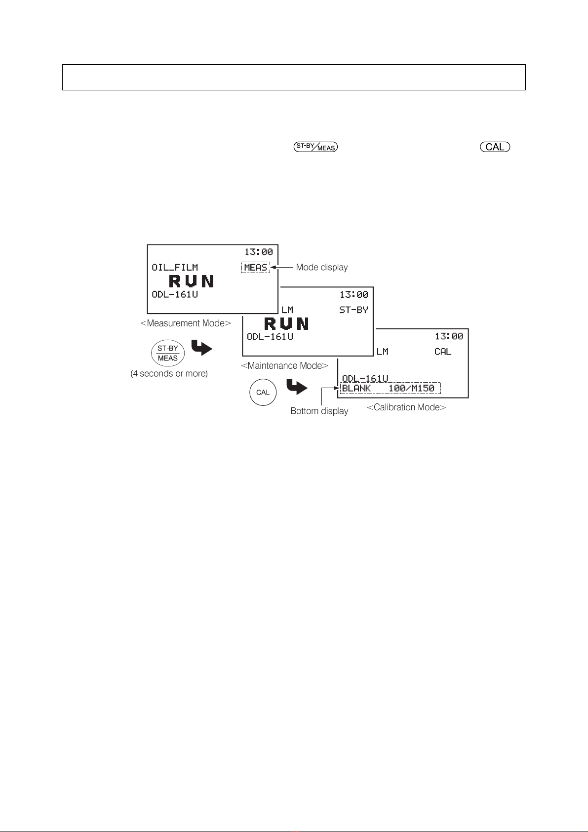
4. Calibration
In addition to 3. “Alarm Operation Check”, perform calibration of detection sensitivity once every 6
months by the following procedure:
①Switch to the calibration mode. ⋅⋅⋅⋅⋅⋅ Press for 4 seconds or more then press
(when “MEAS” is displayed).
•After operation, the mode display and bottom display change as follows:
•Mode display: “MEAS” →“ST-BY” →“CAL”
•Bottom display: (Hidden) →“BLANK ****/M****”
〔NOTE〕•When “HOLD” is set for the output type (OUT TYPE), the transmission value
immediately prior to switching to the maintenance mode is output as a transmission fixed
value. When “DUMMY” is set, the preset value is output. >> 5.3(6) “Analog output”
•In the maintenance mode, the instrument error signal contact and oil alarm signal contact
are not output. If you want to check these two signals, do not switch to the maintenance
mode.
②Place a rubber sheet, etc. ⋅⋅⋅⋅⋅⋅ Place a lusterless rubber sheet or hubby paper, etc. directly below
the detector.
③Check the detection level. ⋅⋅⋅⋅⋅⋅ Compare two numeric values on the bottom display and check the
difference between them. If the difference is large, proceed with ④. If small, proceed with ⑤.
•Bottom display: “BLANK ⋅⋅⋅⋅⋅⋅ ****/M****”
•“M****” ⋅⋅⋅⋅⋅⋅ Indicates the maximum value of the received-light detection level. The value is
reset every 10 seconds and the maximum value is updated and displayed.
•“****” ⋅⋅⋅⋅⋅⋅ Indicates the reflected-light detection level stored during the previous calibration
operation.
•BLANK calibration standard value ⋅⋅⋅⋅⋅⋅ 0 to 3000
•WATER calibration standard value ⋅⋅⋅⋅⋅⋅ 17000 to 23000
•OIL calibration standard value ⋅⋅⋅⋅⋅⋅ 30000 to 40000
④When the difference of the numeric values is large. ⋅⋅⋅⋅⋅⋅ Check the following points and correct
appropriately and perform ③again.
Table of contents


